Project 1 (Mini Project on Vehicle Direction Detection
Aim Of The Challanges
General Overview:
Identifying the direction of the vehicle is one of the important & diverse features in Autonomous driving & Advanced Driver Assistance Features. This particular sub-feature of identifying the direction of vehicle is basically identifying the direction the vehicle is taking based on the camera input.
Camera reads the road signs & stores into its memory with unique values for left turn, right turn & straight drive. Depending on the direction it is taking, final indication is given to the driver – as an indication if he is driving in the recommended direction or not.
Vehicle Direction Determination can also be coupled along - side features like GPS systems to identify whether the vehicle is reaching its destination in an optimized manner. This sub feature can also be used along with Lane Detection, Highway Warning, Ramp Entry / Exit in Wrong Way Detection etc.
Objective of Mini Project:
- Development of MATLAB Simulink model as per requirement.
- Tag the requirements to the simulink model; tagging requirement 1 & requirement 2 to their corresponding subsystems is fine.
- MBD compliant changes, Data Dictionary creation & code generation is added advantage, and that is not scope of this project.
- If choosing code generation, Storage class for Input signals: ImportedExtern; Storage class for Output signal: Export to File; Storage class for local signals: localizable; Storage class for calibration signals: Const.
- Choose sample time for all signals as 0.01s
Requirement - 1:
- Steering wheel input as yaw rate (Signal name: SteeringWheel_YawDegreeInput) is the input for this system.
- This is compared against 3 angular values, one each for left turn, right turn & straight drive (Calibration Values: Right_Turn_AngularLimit, Left_Turn_AngularLimit, Straight_Drive_Steering_Angle) to say which specific direction the steering wheel is turning towards.
- Use switch blocks to compare & develop this requirement. Keep this requirement in a subsystem & output of this requirement is a local signal (Signal Name: Vehicle_Turn_Status).
Requirement – 2:
- Keep this requirement as a separate subsystem. Inputs to this requirement are local signal from requirement 1 (Signal Name: Vehicle_Turn_Status) & an input signal from camera (Signal Name: CameraInput_RoadSign), which confirms the occurrence of a road sign.
- Signal Vehicle_Turn_Status is compared against calibration values (Calibration Values: RightTurn_RoadSign, LeftTurn_RoadSign, Straight_RoadSign), if each of them is found equal, then each of the three corresponding output is compared against the camera input signal,
- Using a logical operator block, only one among them is finally given as output signal (Signal Name: Vehicle_Direction_Indicator).
ANSWER:
First we have to create a simulink data dicitionary file in the format of SLDD file.
SLDD FILE CREATION:
The Sldd data files are related to the Matalb and simulink simulations.The sldd file stores the data it like matalab workspace.
- To create a SLDD file open the simulink blank model and go to modelling properties.
- Then select link to data dicitionary option to create a sldd file.
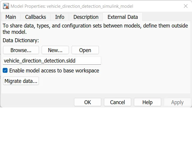
we have to create a signal and constant parameters signal . so that we have to select the model properties select external data to create a new SLDD FILE . In that we are selecting the design data ton create a slld data
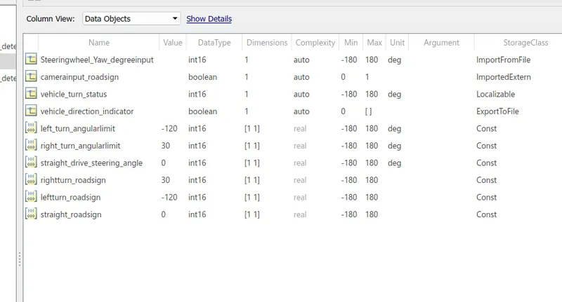
After designing the sldd file right click on the sldd file to saved as vehicle_ direction _detection .slld file.
MODELING :
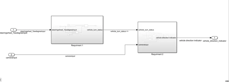
As per the given requirments in the challange we are creating a simulink based models for Autonomous vehicle derection detection.
First thing we are creating a main subsystem and naming as a Vehicle direction detection.
- Added a subsystem to the wmpty simulink model and named it as vehicle direction.
- It connects with two inputs and one outputs
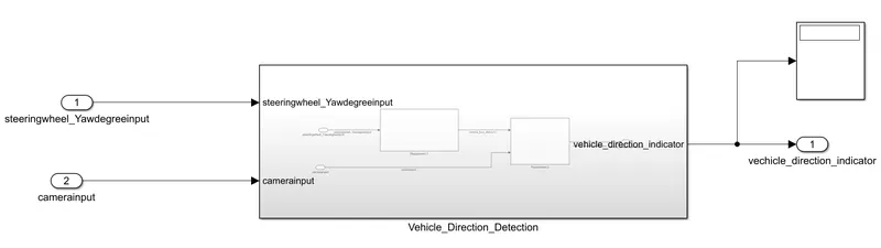
Then double click the subsystem to create a two new substem as per the requiorments.
- The two subsystems are named as a requirments 1 & 2.
- the input and outputs are according to the the given data created.
- now we are model the subsystems.
Requirments 1:
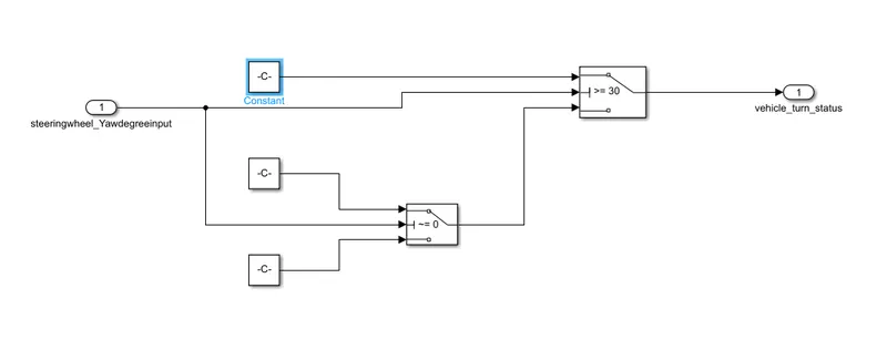
- Steering wheel input as yaw rate (Signal name: SteeringWheel_YawDegreeInput) is the input for this system.
- This is compared against 3 angular values, one each for left turn, right turn & straight drive (Calibration Values: Right_Turn_AngularLimit, Left_Turn_AngularLimit, Straight_Drive_Steering_Angle) to say which specific direction the steering wheel is turning towards.
- Use switch blocks to compare & develop this requirement. Keep this requirement in a subsystem & output of this requirement is a local signal (Signal Name: Vehicle_Turn_Status).
Requirement – 2:
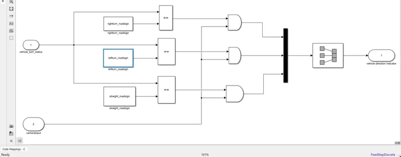
- Keep this requirement as a separate subsystem. Inputs to this requirement are local signal from requirement 1 (Signal Name: Vehicle_Turn_Status) & an input signal from camera (Signal Name: CameraInput_RoadSign), which confirms the occurrence of a road sign.
- Signal Vehicle_Turn_Status is compared against calibration values (Calibration Values: RightTurn_RoadSign, LeftTurn_RoadSign, Straight_RoadSign), if each of them is found equal, then each of the three corresponding output is compared against the camera input signal,
- Using a logical operator block, only one among them is finally given as output signal (Signal Name: Vehicle_Direction_Indicator).
SUBSYSTEM:
Tagging:
In the challnge we are tagging the given data in challnge and connecting with the simulink model by selecting the required subsytems and right click and select the requirment and select the Link the selection in word to link the data.
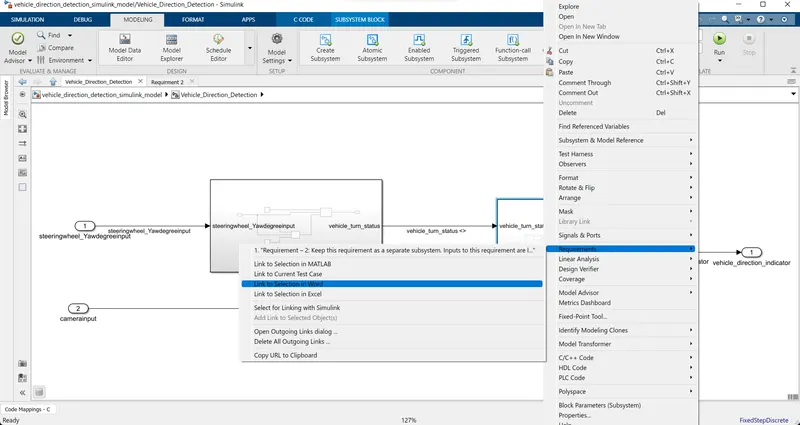
do the same process for the both requirments as per the model we are created.
SOLVER SETTINGS:"
Solver settings is one of the most important to simulate the model.
To open the solver settings go o the modellind settings or use the command ctrl+E to open the medelling properties.
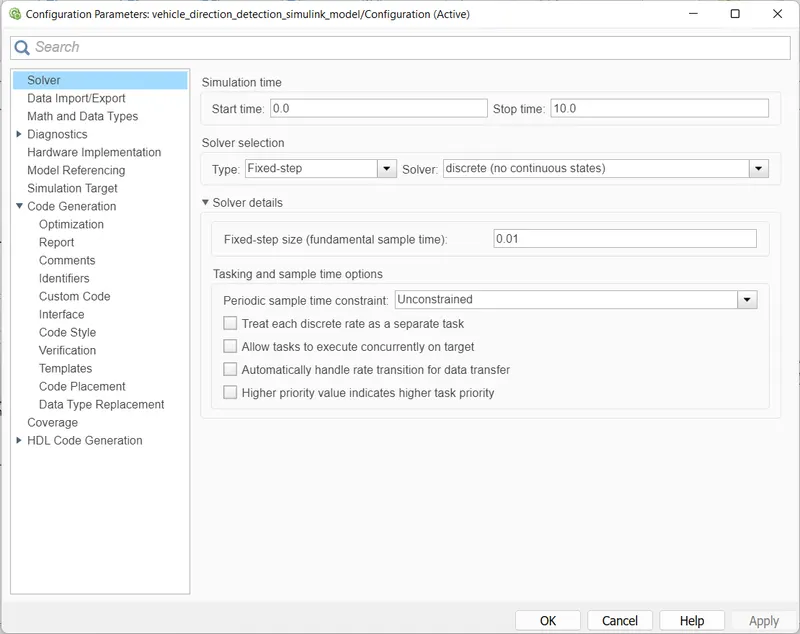
In that we are selecting the solver confriguration.
- click the solver to model the solver parameters.
- now change the type to fixed step and solver to discrete(no continuous states) and take sample trimes as 0.01 seconds. then click ok to save the sover confriguration.
In that same confriguration window the another setting to model, which is code generation click code generation
- choose the system target fike as ert.tlc by clicking on the browser option.
MAB Guidelines:
MAB guidlines are a set of modeling guidlines development by an industryu working group method of a matlab, simulink, stateflow, and coder.
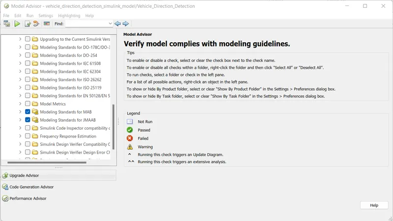
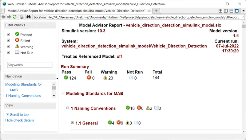
- To perform a the MAB guidlines test on our bsimulink model;, go to modeling section and select model advisor which is at the top left corner on simulink window.
- By using the model advisor to verfiy the compliance of your model with the mathworks MAB guidlines.
- In the model advisor there are many numbers of mab guidlines are there in that we are selecting the standard MAB gudlines alone.
- After selecting Mab click on run check box to run the MAB performance test .
performance test is running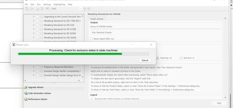
After testing it show the result whether any warnings of failed etc
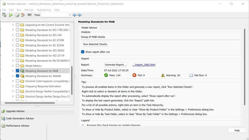
Report for the performance test:
Generating the C CODINGS:
Goto the co code slection and click on bulid option to bulid the codes.
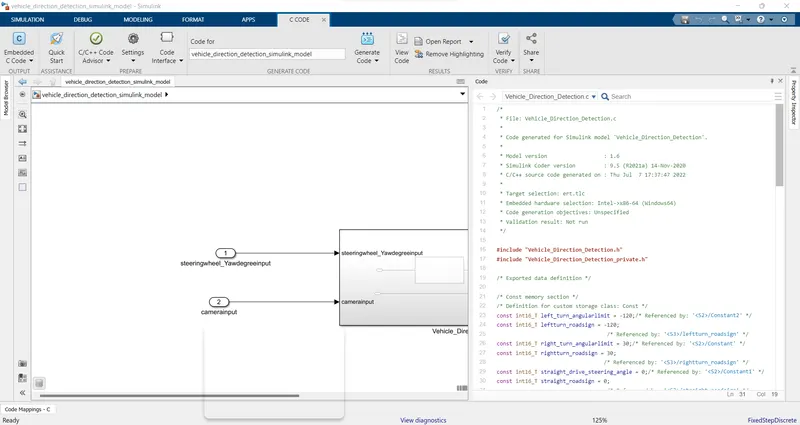
codings:
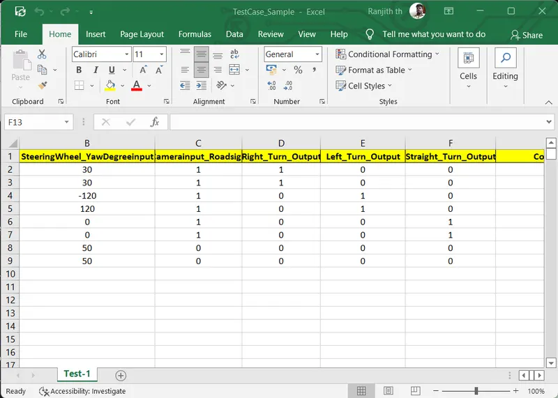
- MIL testing means that the model and its environment are simulated in the modeling framework without any physical hardware components. Refers to the kind of testing done to validate the behavior of the auto generated code used in the controller
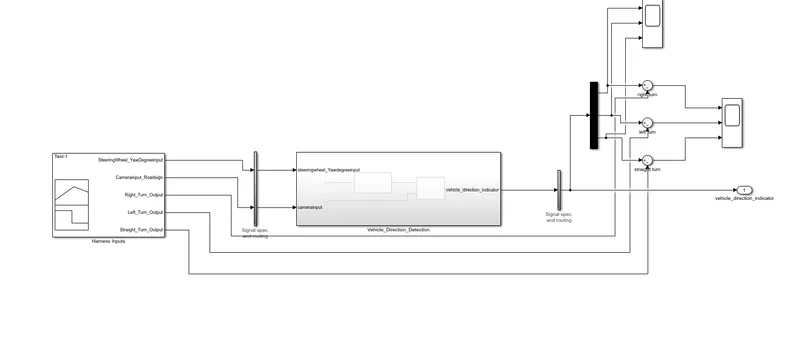
- To perform MIL test, first right cliuck on vehicle direction detection subsystem and select test harness and then create a vehicle direction
- Then create a input for that crating a signal bulider block. .
Signal bulider:
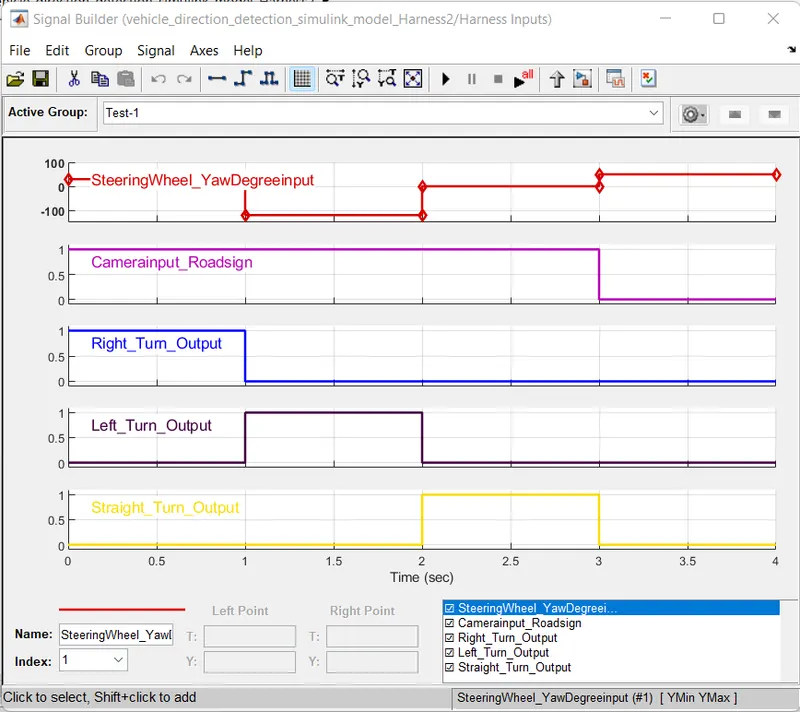
Here we are importing the datas to signal bulider to create a input signals, we can add the output signals, so first we have to add the demux block and thre sum blocks to connect signal
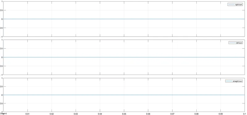
then we taking the simulation time as 0.1 s
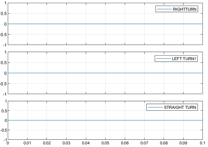
scope:
SIL TEST:
Software-in-the-loop (SIL) is a method of testing and validating code in a simulation environment in order to quickly and cost-effectively catch bugs and improve the quality of the code.
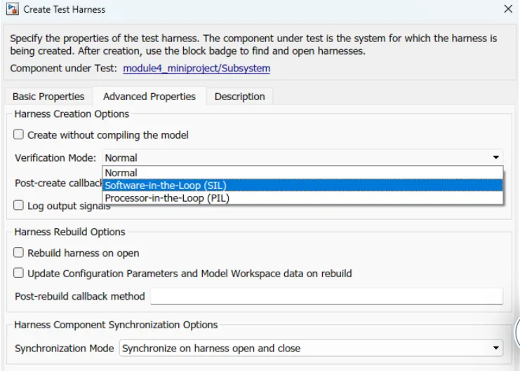
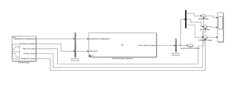
The same procees here we are doing for SIL , but the small difference here we are using a codings
In the signal bulider we are selecting the inputs as signalbulider and in advanced Properities we are changing the validation modes to Software in loop SIL.
Simulink model for SIL:
Scope for Sil: