Project 1 (Mini Project on Vehicle Direction Detection
Objective of Project:
- Development of MATLAB Simulink model as per requirement.
- Tag the requirements to the simulink model; tagging requirement 1 & requirement 2 to their corresponding subsystems .
- After creating the model performed model advisory test, mil and sil test .
- MBD compliant changes, Data Dictionary creation & code generation is added advantage.
Task:
This particular sub-feature of identifying the direction of vehicle is basically identifying the direction the vehicle is taking based on the camera input.
Camera reads the road signs & stores into its memory with unique values for left turn, right turn & straight drive.
Depending on the direction it is taking, final indication is given to the driver – as an indication if he is driving in the recommended direction or not.
Vehicle Direction Determination can also be coupled along - side features like GPS systems to identify whether the vehicle is reaching its destination in an optimized manner.
1 steps:
Creation of sldd file :-
A data dictionary is a persistent repository of data that are relevant to your model.
we can also use the base workspace to store design data that are used by your model during simulation.
However, a data dictionary provides more capabilities.
The dictionary stores design data, which define parameters and signals, and include data that define the behavior of the model.
The dictionary does not store simulation data, which are inputs or outputs of model simulation that enter and exit Inport and Outport blocks.
- In the Current Folder pane of the MATLAB Command Window, navigate to the location of the data dictionary.
- Double-click the name of the dictionary. In the Model Explorer,
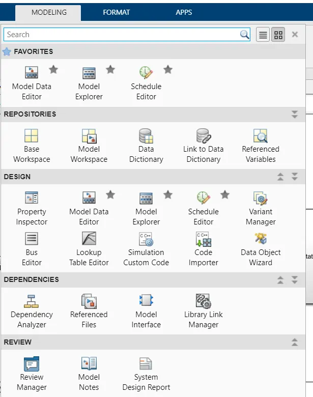
- click on the link to data dictionary
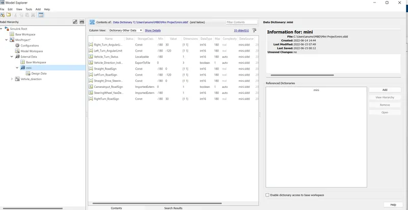
- after that i have created a new sldd file and save as name of mini.sldd.
- defined the all constant and signal according to the given requirment,unit initial values ect.
2.Step
model development:
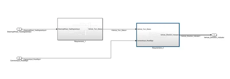
i have created subsystem 1 , and subsystem 2 sepreatlly , according to the requirment .
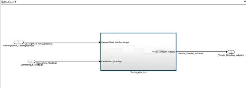
defined the condition .
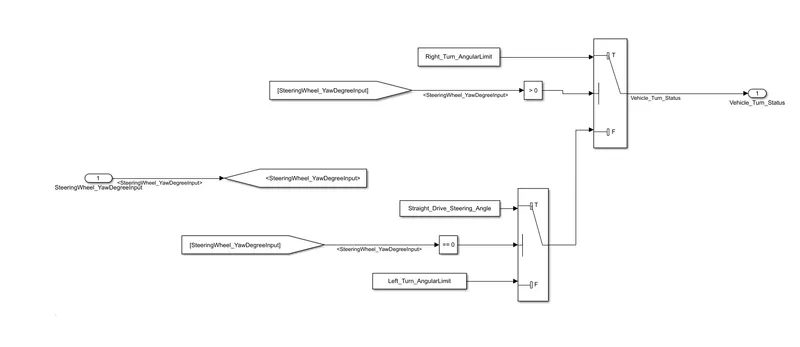
given below conditions showing the first subsystem condition (Requirment_1)
Working: here switch is using such as if and else condition .
- SteeringWheel_YawDegreeInput should be greater than 0.
- vehicle turn status will show right turn.
- otherwise it will goes in else condition.
- switch_2 will goes in working
- if it is true in vehicle turn status will show straight drive angle.
- otherwise it will shows left_turn.
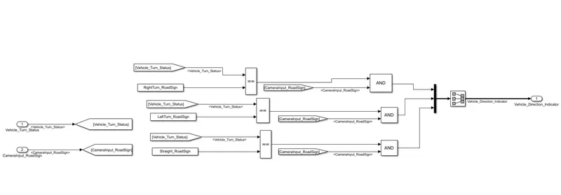
given below conditions showing the first subsystem condition (Requirment_2)
- output is vehicle direction indicator.
- input is camerainput, RightTurn_Roadsign.
- AND gate is using to verify the condition when vehicle_Turn status and cemerainput condition is true then AND logic will gives input true , then will goes in the signal conversion.
3. step
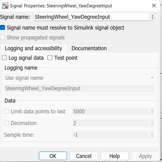
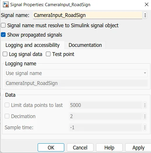
signal Resolving and signal propagation
- when we first time naming or labeling the signal its called resolving the signal.
- By the resolving signal and const it associatted with the properties of the signal which defined in sldd its linked with parameters.
- after that its called propogation, when we again labeled its or again used in the model.
step 4
Tagging Procedure : The tagging process involves using labels to provide content with additional information (using a particular set of keywords).
Tagging is primarily used to make information easier to find or link to.
step 5
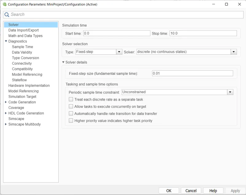
Solver settings :
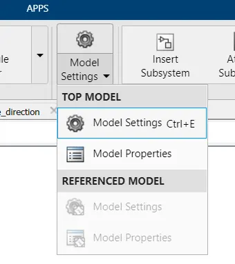
for run the model according to our time we are considering the fixed-step solver and taking fixed-step size (sample time)=0.01
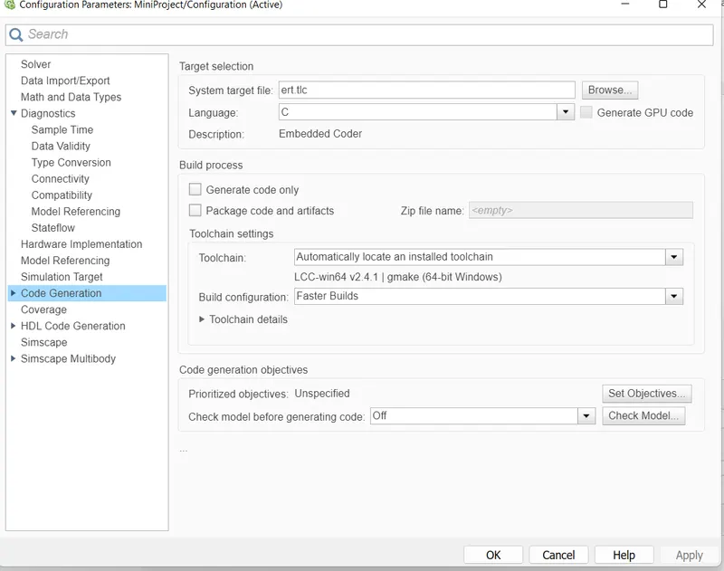
Code Generation: this settings changes models in c code.
by default System target file set grt.tlc but we need to changed is ert.tlc.
step 6
model advisor check:
- To verify the configuration parameters for your model, you can create a configuration parameter check.
- Custom checks provide you with the ability to specify which conditions and configuration settings the Model Advisor reviews and at which stage during model development the Model Advisor reviews them.
- you can create custom checks that automatically run while you edit the model and interactively run in the Model Advisor.
- given below images shows the menu of model advisor .
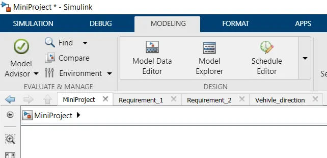
- after selecting this will get two options
- 1. by product , 2nd task
- i have selected by task under the MAB guidlines.
- run the MAB guidlines and genrate the reports
- reports contains fail,pass, not run, warning condition and help to understand the model error with model recommendations.
- generated report also attached in below
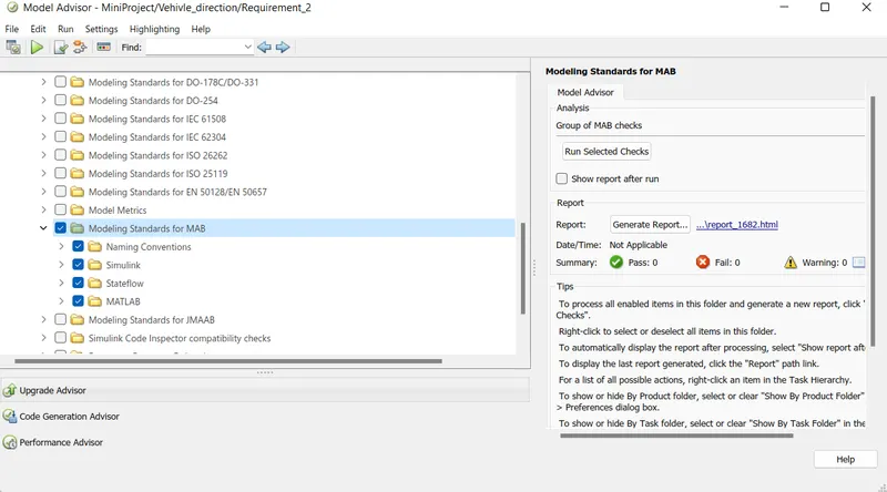
now run the model to the check that any error is falling or not.
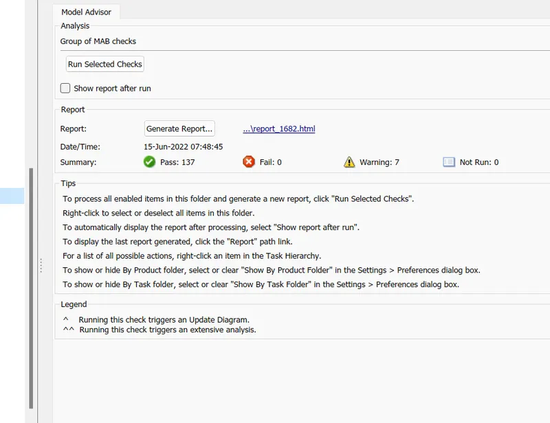
after model advisor run condition we need to keep in mind if any fails condition will be their ,then we can not perform mil and sil test .
so that fail condition have to 0.
if condition occurs then need to solve this error. then move ahead.
step 7
Model-in-Loop testing:
Test Harness
- Creating the subsystem
- Right click on subsystem ,go to the test Harness
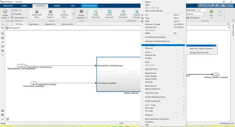
- After created the subsystem , window will pop up.
-
changing the source of inport and select the signal builder
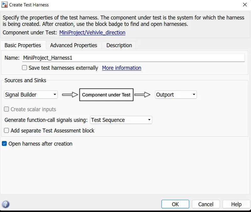
- new window will appear and shows like below and name shows MiniProject_Harness1
- excel file is imported in the signal builder block
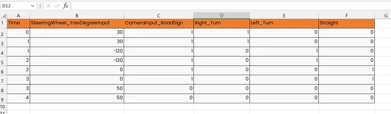
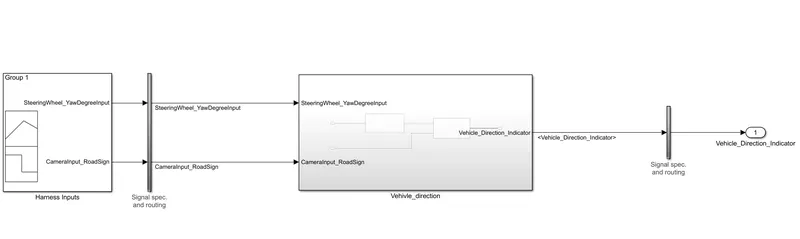
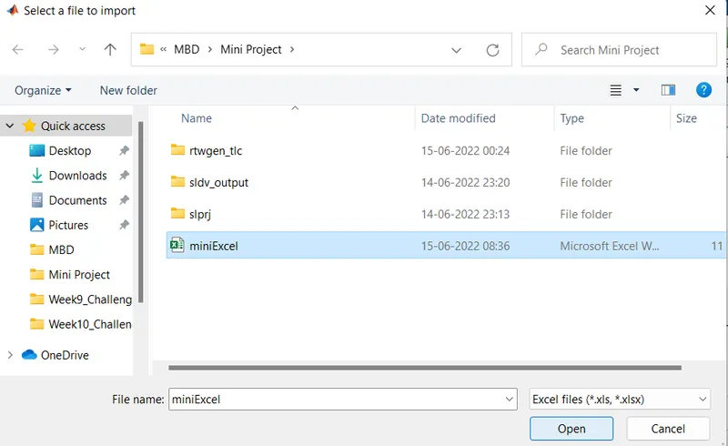
- After importing and saved the changes .
-
now we are trying to verify the output of actual and expected .
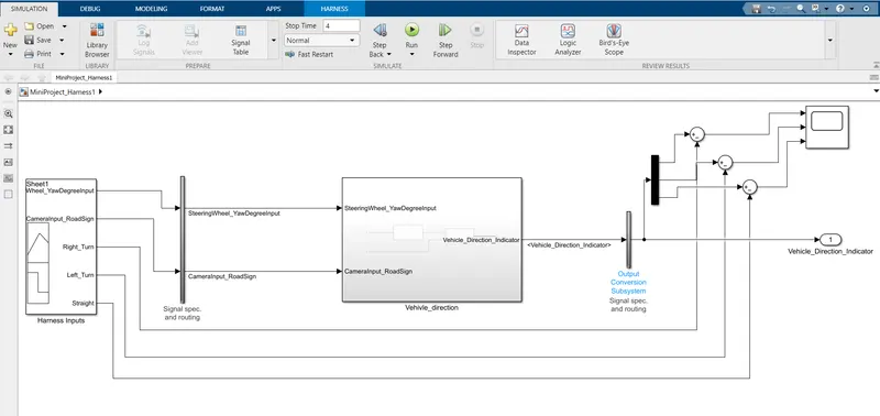
for this I have used sum block and subtract the signal will verify the output.
simply we are taking the difference and difference should be 0.
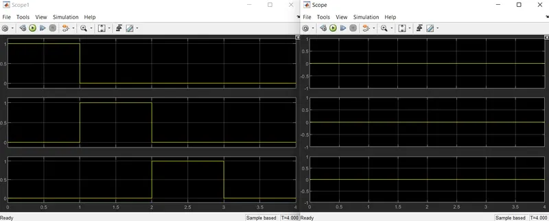
step 8:
Software - in - Loop:
- I am creating a test case excel sheet. in excel first column for time, input, ....also saved in same folder.
- click on solver, i choose the solver type it is fixed because i want to performed test according to test time, also set fixed step -size and stop time.
- in the SIL test we need to do code generation setting, for screenshot showing above.
- for the sil test we need to converted model in embedded coder , c language , so system target file choose ert.tic .
Test Harness
creating the subsystem .
Right click on subsystem ,go to the test Harness
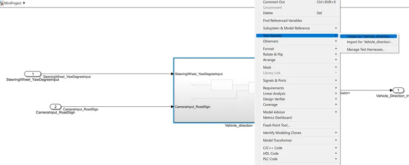
Go to the in advanced properties select software-in-loop and press ok.
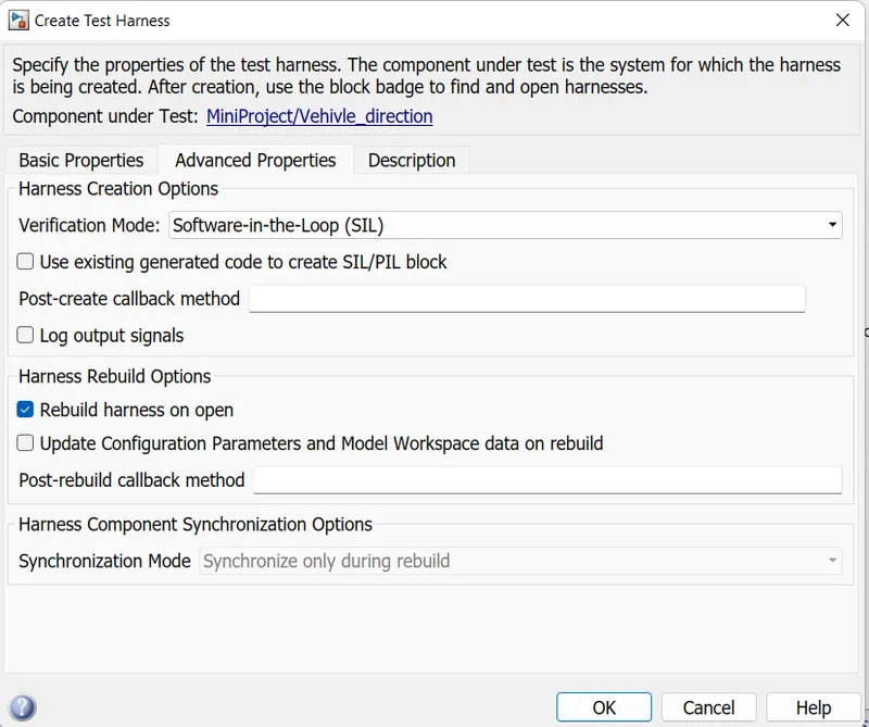
the subsystem is not supported by this workflow, when I am going to selecting sil test in advanced setting option
given below erroe is comming up .
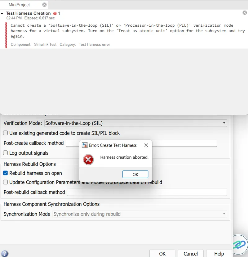
so resolve the error right click on subsystem and select block parameter property .
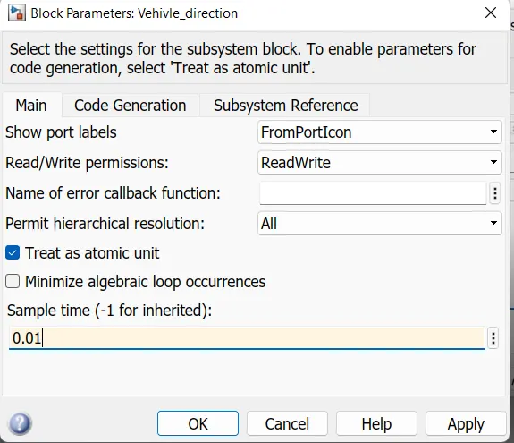
check the Treat as atomic unit option .
here i am taking the sample time 0.01 because my model sample time is 0.01.
and now these model is converted into the c, code.
applied ok the automatic new window will appear, below showing
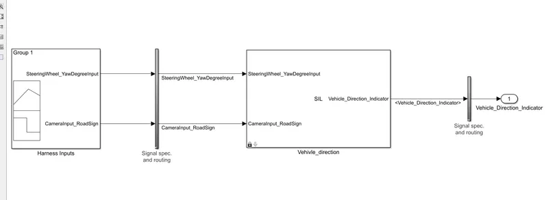
after loading we can observed signal builder create 5 input to bus selector.
When you run a SIL simulation, you must configure your hardware implementation settings (characteristics such as native word sizes) to allow compilation for your development computer.
These settings can differ from the hardware implementation settings that you use when building the model for your production hardware.
above screenshot we can observed a arrow mark , hovering on this arrow subsystem model shows.
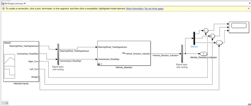
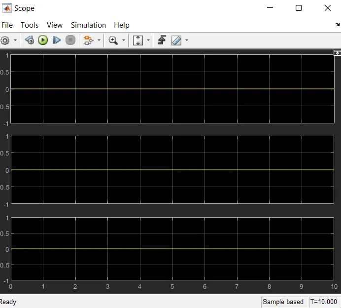
now we are trying to verify the output of actual and expected.
for this i have used sum block and subtract the signal will verify the output.
simply we are taking the difference, difference should be 0.
step 9:
go to the APP option after click on it you will get Embedded coder option.
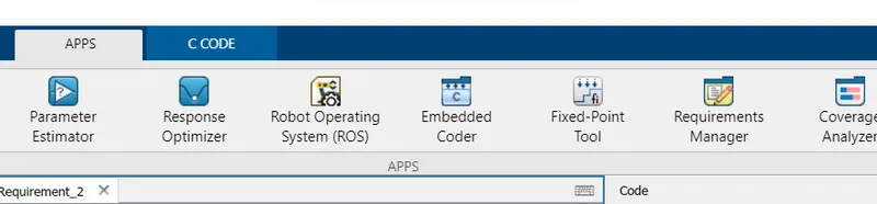
select it , go on build option.
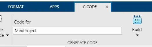
by this our code will converted into the c code.
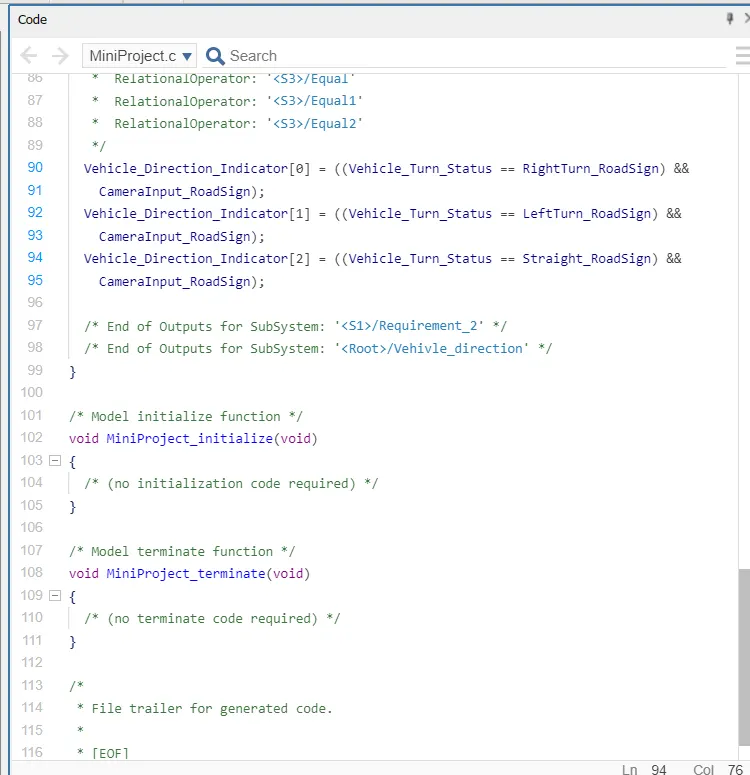
it will generate a c code file in folder or same location.
and code window shows below: