Project 1 (Mini Project on Vehicle Direction Detection
Objective of the project-
The objective of the model create the model as per the requirment specified in matlab and simulink.
Tagging the model as per the requirment specified in the reuirement subsystem.
Creating data dictionary model as the per required for sil and mil test,And most important creating an c code using embedded coder.
Task-
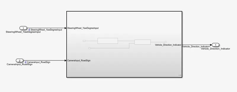
The inputs to the system are the steering wheel angular input given as yaw rate(signal name:Steering wheel_YAwDegreeeInput)and a input signal from camera(Signal Name:CameraInput_roadsign)which confirms the occurence of a road sign.
A camera is going to read the road sign adn it's give to signal according to the given input to the driver,Depending on the direction then vehicle decides whether it's going in correct direction or not.
The Output of the vehicle is boolean value(SIgnal
Name:Vehicle_Direction_Indicator)which specifies whether it's going right or wrong.
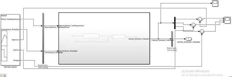
Simulink model of the subsytem-
Requirment1 Tagging-
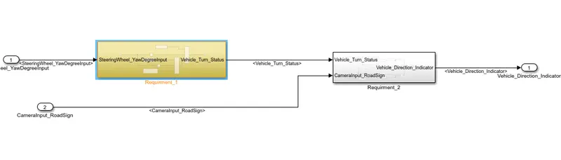
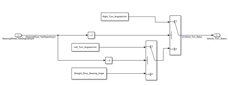
In requirment the Steering wheel input as yaw rate (Signalname: SteeringWheel_YawDegreeInput) is the input for this system.
- This is compared against 3 angular values, one each for left turn, right turn & straight drive (Calibration Values: Right_Turn_AngularLimit, Left_Turn_AngularLimit, Straight_Drive_Steering_Angle) to say which specific direction the steering wheel is turning towards.
- Use switch blocks to compare & develop this requirement. Keep this requirement in a subsystem & output of this requirement is a local signal (Signal Name: Vehicle_Turn_Status).
Requirment -2
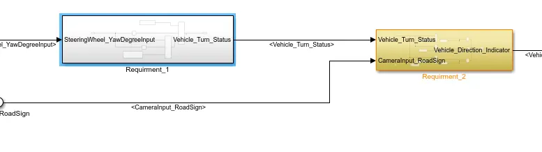
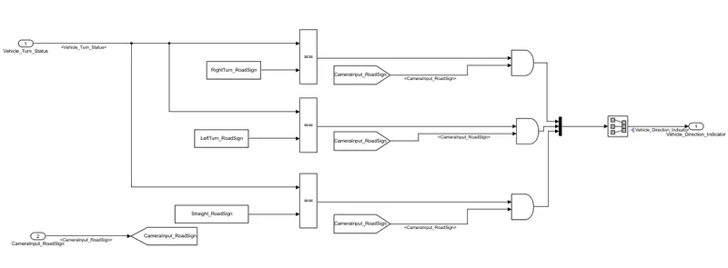
- Keep this requirement as a separate subsystem. Inputs to this requirement are local signal from requirement 1 (Signal Name: Vehicle_Turn_Status) & an input signal from camera (Signal Name: CameraInput_RoadSign), which confirms the occurrence of a road sign.
- Signal Vehicle_Turn_Status is compared against calibration values (Calibration Values: RightTurn_RoadSign, LeftTurn_RoadSign, Straight_RoadSign), if each of them is found equal, then each of the three corresponding output is compared against the camera input signal,
- Using a logical operator block, only one among them is finally given as output signal (Signal Name: Vehicle_Direction_Indicator).
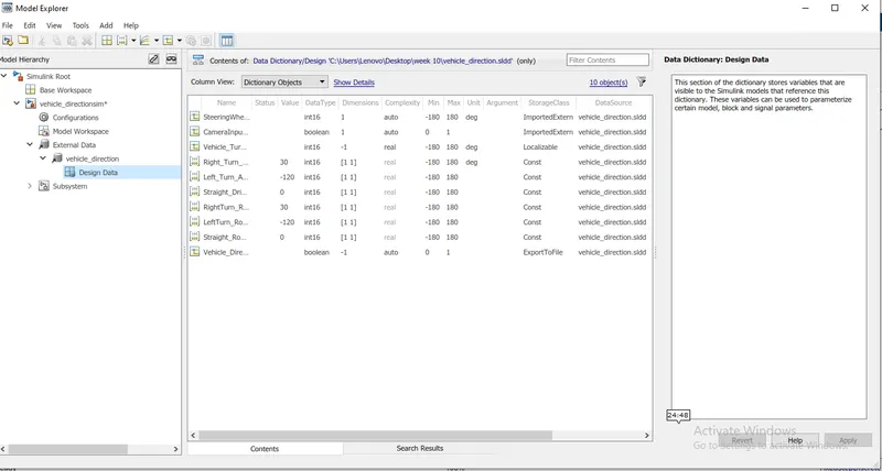
Sldd -
the sldd tagging is done after linkin to data dictionary.
Model advisor check-
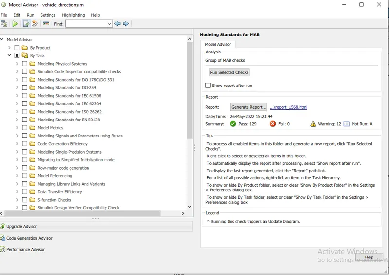
There were only 12 warning so that's good enough,next we can perform mil and sil test.
MIL test-
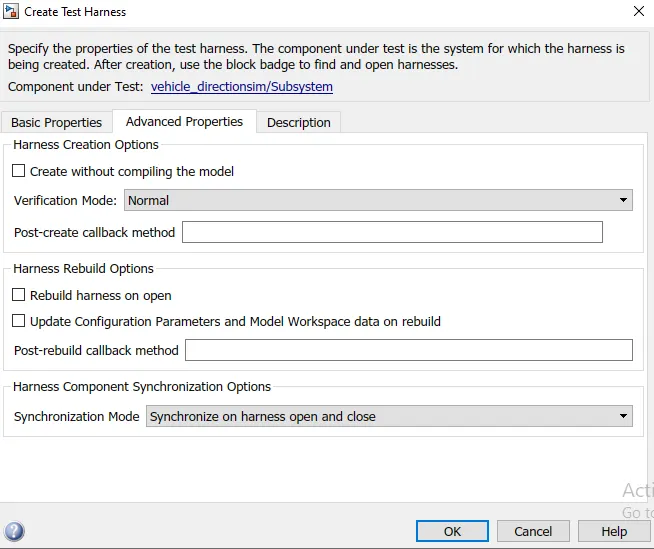
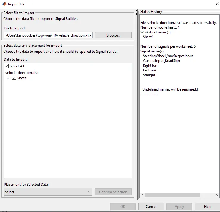
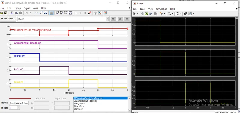
Importing the excel file-
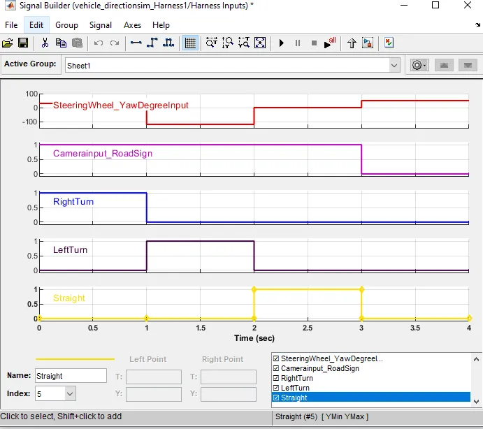
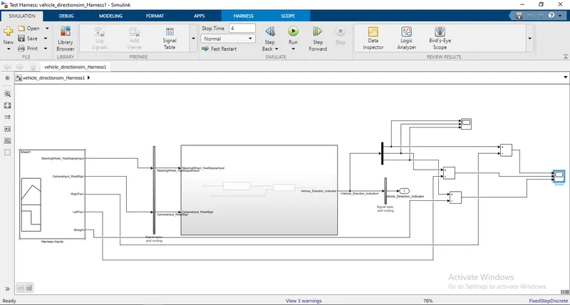
MIL
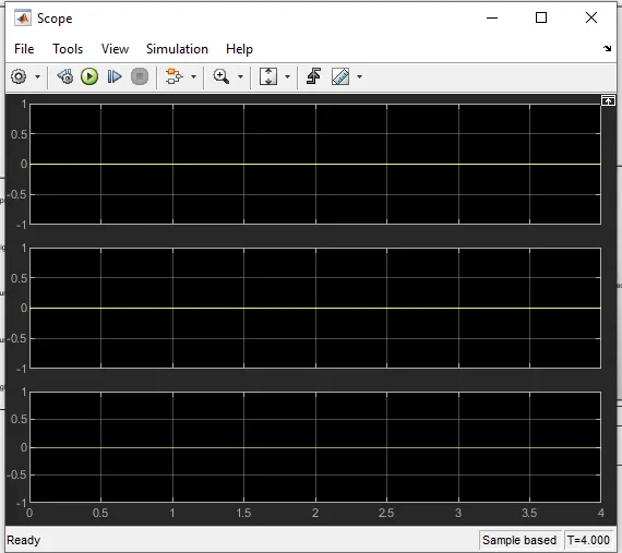
test result-
SIL test-
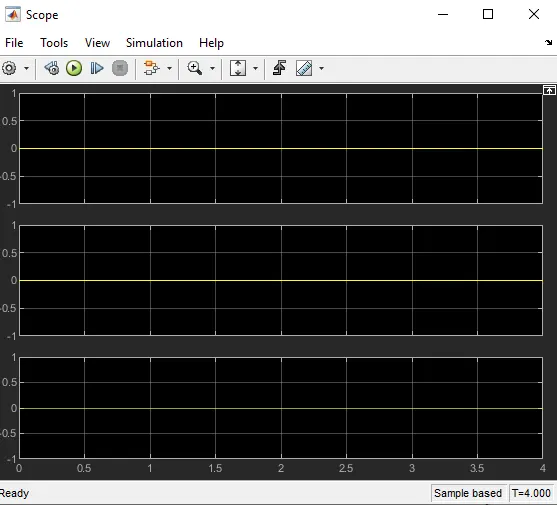
Test result-
Generated code-
 * File: vehicle_directionsim_Harness2.c
 *
 * Code generated for Simulink model 'vehicle_directionsim_Harness2'.
 *
 * Model version                  : 1.0
 * Simulink Coder version         : 9.3 (R2020a) 18-Nov-2019
 * C/C++ source code generated on : Thu May 26 14:42:57 2022
 *
 * Target selection: ert.tlc
 * Embedded hardware selection: Intel->x86-64 (Windows64)
 * Code generation objectives: Unspecified
 * Validation result: Not run
 */

#include "vehicle_directionsim_Harness2.h"
#include "vehicle_directionsim_Harness2_private.h"

/* Exported data definition */

/* Definition for custom storage class: ExportToFile */
boolean_T Vehicle_Direction_Indicator[3];/* '/Signal Conversion' */

/* Const memory section */
/* Definition for custom storage class: Const */
const int16_T LeftTurn_RoadSign = -120;/* Referenced by: '/Constant1' */
const int16_T Left_Turn_AngularLimit = -120;/* Referenced by: '/Constant1' */
const int16_T RightTurn_RoadSign = 30; /* Referenced by: '/Constant' */
const int16_T Right_Turn_AngularLimit = 30;/* Referenced by: '/Constant' */
const int16_T Straight_Drive_Steering_Angle = 0;/* Referenced by: '/Constant2' */
const int16_T Straight_RoadSign = 0;   /* Referenced by: '/Constant2' */

/* Block states (default storage) */
DW_vehicle_directionsim_Harne_T vehicle_directionsim_Harness_DW;

/* Real-time model */
RT_MODEL_vehicle_directionsim_T vehicle_directionsim_Harness_M_;
RT_MODEL_vehicle_directionsim_T *const vehicle_directionsim_Harness_M =
  &vehicle_directionsim_Harness_M_;

/* Model step function */
void vehicle_directionsim_Harness2_step(void)
{
  /* local block i/o variables */
  real_T rtb_FromWs[5];
  int16_T Vehicle_Turn_Status;
  int16_T tmp;

  /* FromWorkspace: '/FromWs' */
  {
    real_T *pDataValues = (real_T *)
      vehicle_directionsim_Harness_DW.FromWs_PWORK.DataPtr;
    real_T *pTimeValues = (real_T *)
      vehicle_directionsim_Harness_DW.FromWs_PWORK.TimePtr;
    int_T currTimeIndex = vehicle_directionsim_Harness_DW.FromWs_IWORK.PrevIndex;
    real_T t = vehicle_directionsim_Harness_M->Timing.t[0];

    /* Get index */
    if (t <= pTimeValues[0]) {
      currTimeIndex = 0;
    } else if (t >= pTimeValues[7]) {
      currTimeIndex = 6;
    } else {
      if (t < pTimeValues[currTimeIndex]) {
        while (t < pTimeValues[currTimeIndex]) {
          currTimeIndex--;
        }
      } else {
        while (t >= pTimeValues[currTimeIndex + 1]) {
          currTimeIndex++;
        }
      }
    }

    vehicle_directionsim_Harness_DW.FromWs_IWORK.PrevIndex = currTimeIndex;

    /* Post output */
    {
      real_T t1 = pTimeValues[currTimeIndex];
      real_T t2 = pTimeValues[currTimeIndex + 1];
      if (t1 == t2) {
        if (t < t1) {
          {
            int_T elIdx;
            for (elIdx = 0; elIdx < 5; ++elIdx) {
              (&rtb_FromWs[0])[elIdx] = pDataValues[currTimeIndex];
              pDataValues += 8;
            }
          }
        } else {
          {
            int_T elIdx;
            for (elIdx = 0; elIdx < 5; ++elIdx) {
              (&rtb_FromWs[0])[elIdx] = pDataValues[currTimeIndex + 1];
              pDataValues += 8;
            }
          }
        }
      } else {
        real_T f1 = (t2 - t) / (t2 - t1);
        real_T f2 = 1.0 - f1;
        real_T d1;
        real_T d2;
        int_T TimeIndex= currTimeIndex;

        {
          int_T elIdx;
          for (elIdx = 0; elIdx < 5; ++elIdx) {
            d1 = pDataValues[TimeIndex];
            d2 = pDataValues[TimeIndex + 1];
            (&rtb_FromWs[0])[elIdx] = (real_T) rtInterpolate(d1, d2, f1, f2);
            pDataValues += 8;
          }
        }
      }
    }
  }

  /* DataTypeConversion: '/Data_Conversion_1' */
  if (rtb_FromWs[0] < 32768.0) {
    if (rtb_FromWs[0] >= -32768.0) {
      tmp = (int16_T)rtb_FromWs[0];
    } else {
      tmp = MIN_int16_T;
    }
  } else {
    tmp = MAX_int16_T;
  }

  /* Outputs for Atomic SubSystem: '/Subsystem' */
  /* Switch: '/Switch' incorporates:
   *  Constant: '/Constant'
   *  Constant: '/Constant2'
   *  Constant: '/Constant'
   *  Constant: '/Constant'
   *  DataTypeConversion: '/Data_Conversion_1'
   *  RelationalOperator: '/Compare'
   *  RelationalOperator: '/Compare'
   *  Switch: '/Switch1'
   */
  if (tmp > 0) {
    Vehicle_Turn_Status = Right_Turn_AngularLimit;
  } else if (tmp < 0) {
    /* Switch: '/Switch1' incorporates:
     *  Constant: '/Constant1'
     */
    Vehicle_Turn_Status = Left_Turn_AngularLimit;
  } else {
    Vehicle_Turn_Status = Straight_Drive_Steering_Angle;
  }

  /* End of Switch: '/Switch' */

  /* SignalConversion: '/Signal Conversion' incorporates:
   *  Constant: '/Constant'
   *  Constant: '/Constant1'
   *  Constant: '/Constant2'
   *  DataTypeConversion: '/Data_Conversion_2'
   *  Logic: '/AND'
   *  Logic: '/AND1'
   *  Logic: '/AND2'
   *  RelationalOperator: '/Relational Operator'
   *  RelationalOperator: '/Relational Operator1'
   *  RelationalOperator: '/Relational Operator2'
   */
  Vehicle_Direction_Indicator[0] = ((Vehicle_Turn_Status == RightTurn_RoadSign) &&
    (rtb_FromWs[1] != 0.0));
  Vehicle_Direction_Indicator[1] = ((Vehicle_Turn_Status == LeftTurn_RoadSign) &&
    (rtb_FromWs[1] != 0.0));
  Vehicle_Direction_Indicator[2] = ((Vehicle_Turn_Status == Straight_RoadSign) &&
    (rtb_FromWs[1] != 0.0));

  /* End of Outputs for SubSystem: '/Subsystem' */

  /* Update absolute time for base rate */
  /* The "clockTick0" counts the number of times the code of this task has
   * been executed. The absolute time is the multiplication of "clockTick0"
   * and "Timing.stepSize0". Size of "clockTick0" ensures timer will not
   * overflow during the application lifespan selected.
   */
  vehicle_directionsim_Harness_M->Timing.t[0] =
    ((time_T)(++vehicle_directionsim_Harness_M->Timing.clockTick0)) *
    vehicle_directionsim_Harness_M->Timing.stepSize0;

  {
    /* Update absolute timer for sample time: [0.01s, 0.0s] */
    /* The "clockTick1" counts the number of times the code of this task has
     * been executed. The resolution of this integer timer is 0.01, which is the step size
     * of the task. Size of "clockTick1" ensures timer will not overflow during the
     * application lifespan selected.
     */
    vehicle_directionsim_Harness_M->Timing.clockTick1++;
  }
}

/* Model initialize function */
void vehicle_directionsim_Harness2_initialize(void)
{
  /* Registration code */
  {
    /* Setup solver object */
    rtsiSetSimTimeStepPtr(&vehicle_directionsim_Harness_M->solverInfo,
                          &vehicle_directionsim_Harness_M->Timing.simTimeStep);
    rtsiSetTPtr(&vehicle_directionsim_Harness_M->solverInfo, &rtmGetTPtr
                (vehicle_directionsim_Harness_M));
    rtsiSetStepSizePtr(&vehicle_directionsim_Harness_M->solverInfo,
                       &vehicle_directionsim_Harness_M->Timing.stepSize0);
    rtsiSetErrorStatusPtr(&vehicle_directionsim_Harness_M->solverInfo,
                          (&rtmGetErrorStatus(vehicle_directionsim_Harness_M)));
    rtsiSetRTModelPtr(&vehicle_directionsim_Harness_M->solverInfo,
                      vehicle_directionsim_Harness_M);
  }

  rtsiSetSimTimeStep(&vehicle_directionsim_Harness_M->solverInfo,
                     MAJOR_TIME_STEP);
  rtsiSetSolverName(&vehicle_directionsim_Harness_M->solverInfo,
                    "FixedStepDiscrete");
  rtmSetTPtr(vehicle_directionsim_Harness_M,
             &vehicle_directionsim_Harness_M->Timing.tArray[0]);
  vehicle_directionsim_Harness_M->Timing.stepSize0 = 0.01;

  /* Start for FromWorkspace: '/FromWs' */
  {
    static real_T pTimeValues0[] = { 0.0, 1.0, 1.0, 2.0, 2.0, 3.0, 3.0, 4.0 } ;

    static real_T pDataValues0[] = { 30.0, 30.0, -120.0, -120.0, 0.0, 0.0, 50.0,
      50.0, 1.0, 1.0, 1.0, 1.0, 1.0, 1.0, 0.0, 0.0, 1.0, 1.0, 0.0, 0.0, 0.0, 0.0,
      0.0, 0.0, 0.0, 0.0, 1.0, 1.0, 0.0, 0.0, 0.0, 0.0, 0.0, 0.0, 0.0, 0.0, 1.0,
      1.0, 0.0, 0.0 } ;

    vehicle_directionsim_Harness_DW.FromWs_PWORK.TimePtr = (void *) pTimeValues0;
    vehicle_directionsim_Harness_DW.FromWs_PWORK.DataPtr = (void *) pDataValues0;
    vehicle_directionsim_Harness_DW.FromWs_IWORK.PrevIndex = 0;
  }
}

/* Model terminate function */
void vehicle_directionsim_Harness2_terminate(void)
{
  /* (no terminate code required) */
}

/*
 * File trailer for generated code.
 *
 * [EOF]
 */