Project 1 (Mini Project on Vehicle Direction Detection
AIM
- To develop a MATLAB Simulink model of Vehicle Direction Determination
OBJECTIVES
- Develop the Simulink model as per the requirements.
- Tag the requirements to the Simulink model. Requirement 1 & Requirement 2 to their corresponding subsystems
- the Simulink model should be MBD compliant changes
- Perform Data Dictionary creation, Model Advisor Report, and code generation. (MIL and SIL are additionally done for understanding)
General Overview
Determining the direction of the vehicle based on camera input is one of the important & diverse features in Autonomous driving & Advanced Driver Assistance Features. the camera reads the road signs and stores them into its memory with unique values for the left turn, right turn & straight drive. Depending on the results, the driver gets an indication of whether he is driving in the recommended direction or not. this Vehicle Direction Determination can also be used along with other systems like GPS, Lane Detection, Highway Warning, Ramp Entry / Exit in Wrong Way Detection, etc.
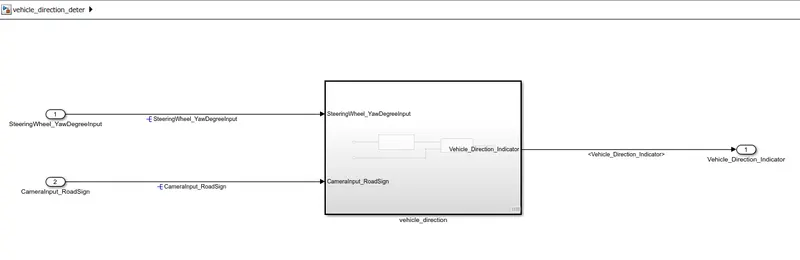
SIMULINK MODEL
MODEL DEVELOPMENT
SLDD creation
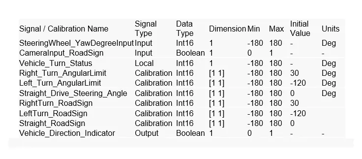
- first, the given input, output signals, and calibration values are added to Simulink Data Dictionary
- Goto modeling - link to data dictionary - create .sldd file

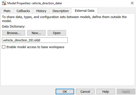
- go to model explorer then under external data, under the dictionary you created, select design data
- by using add Simulink parameter, the constants (calibration) are added
- by using add Simulink signal, the input/output signals are added
- all the data types, values, dimensions, min/max, units, and storage class are entered and saved
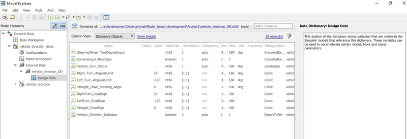
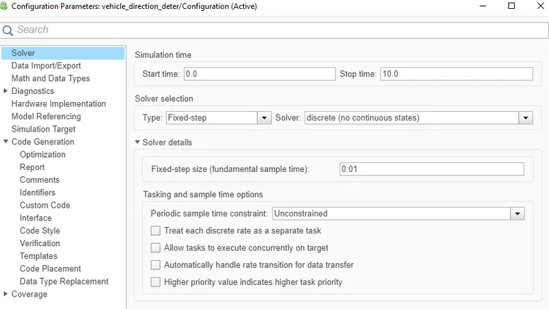
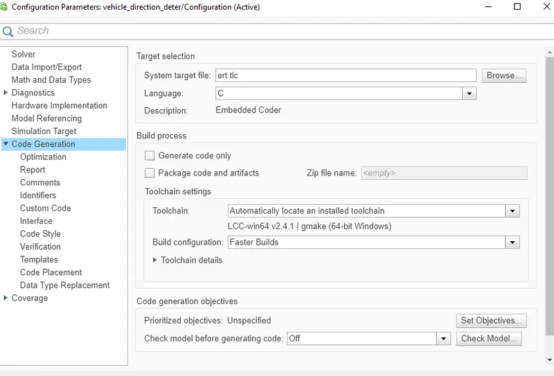
Solver and code generation settings
- goto modeling-model settings
- change the solver settings to fixed type, discrete(no continuous states), sample time-0.01
- in code generation - select browse - ert.tlc embedded coder
Creating subsystem
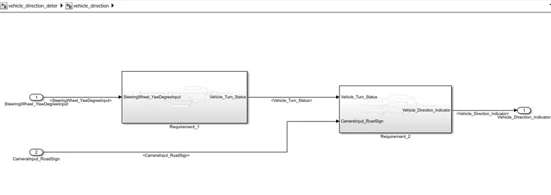
- there are two subsystems for two requirements. Requirement_1 and Requirement_2
- The input signals are SteeringWheel_YawDegreeInput, CameraInput_RoadSign and the output signal is Vehicle_Direction_Indicator
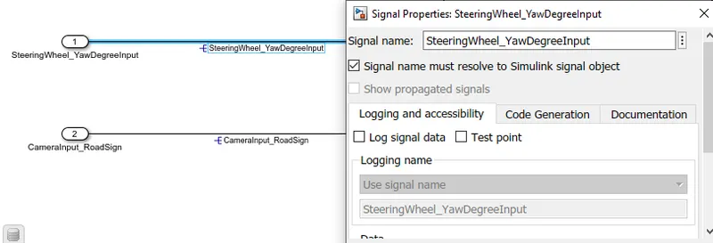
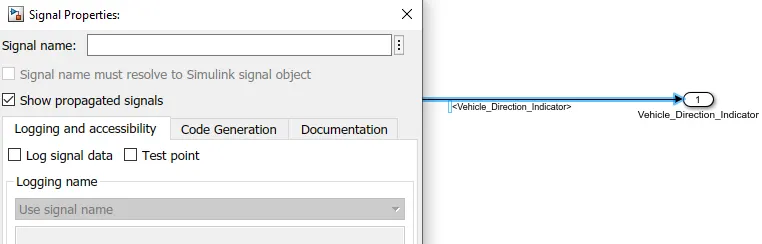
- the signals used for the first time are resolved and after that, the same signals used are propagated.
- to resolve and propagate, right-click on the signal - properties.
- we can also use <> and enter for propagating signals
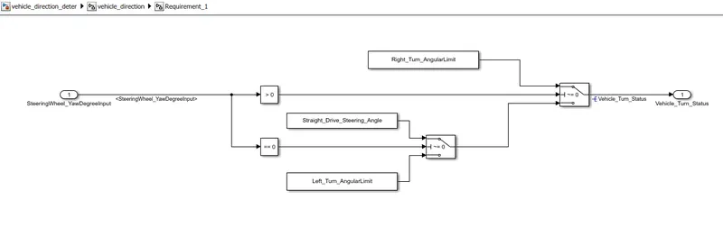
Requirement_1
- SteeringWheel_YawDegreeInput is the input for this system.
- This is compared against 3 angular values, the right turn(positive angle), straight drive(when 0), and left turn(negative angle). the calibration values are given through the SLDD file.
- from the three angles, the direction of the steering wheel can be determined.
- here compare to zero and switch blocks are used.
- when the input is greater than 0 (positive), the right_turn_angularlimit (right turn) is given to the output (Vehicle_Turn_Status)
- when the input is equal to 0, the straight_drive_steering _angle (straight) is given to the output
- when the input is other than the above, ie less than 0 (negative), the left_turn_angularlimit (left turn) is given to the output
- the output (Vehicle_Turn_Status) is considered as local signal as per the requirement
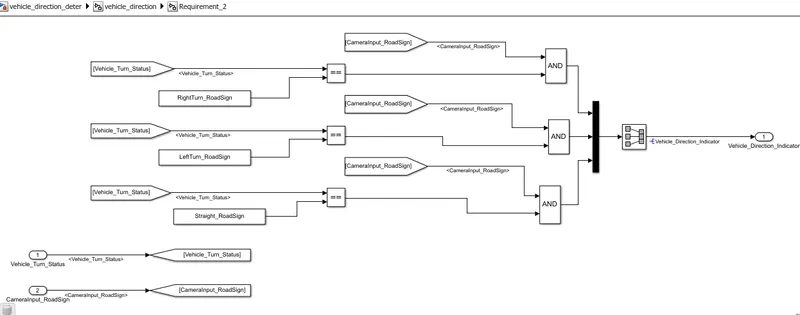
Requirement_2
- there are 2 inputs, Vehicle_Turn_Status from the requirement_1 and CameraInput_RoadSign which confirms the occurrence of a road sign (either 1 or 0)
- the local signal Vehicle_Turn_Status is compared against three calibration values (RightTurn_RoadSign, LeftTurn_RoadSign, Straight_RoadSign) using relational operator and if found to be equal, then the corresponding output is compared against the CameraInput_RoadSign using logical AND block and the output is given to Vehicle_Direction_Indicator(output signal) through mux and signal conversion blocks
Requirement tagging
- open the word file containing the requirement document
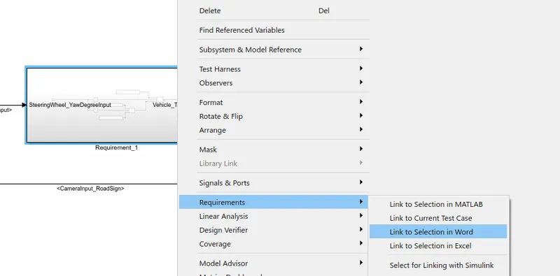
- select the word (Requirement - 1) on the word file which is going to be tagged with the subsystem (Requirement_1)
- then right-click on the subsystem -- Requirements -- Link to selection in word.
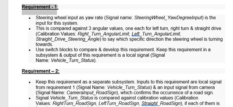
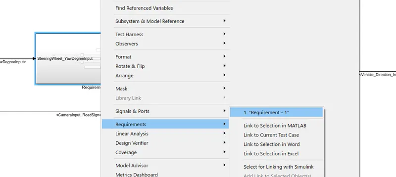
- after linking, right-click on subsystem -- requirements -- select the word which was tagged.
- the requirement document will be opened automatically
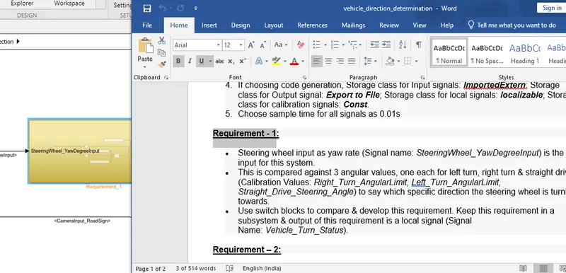
- the same procedure is used for the second subsystem as well.
Model Advisor Check
- The Model Advisor checks the created Simulink model follows, proper conditions and configuration settings
- The Model Advisor checks can help you verify compliance with industry standards and guidelines.
- select modeling -- model advisor
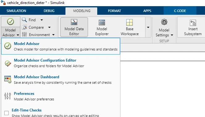
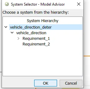
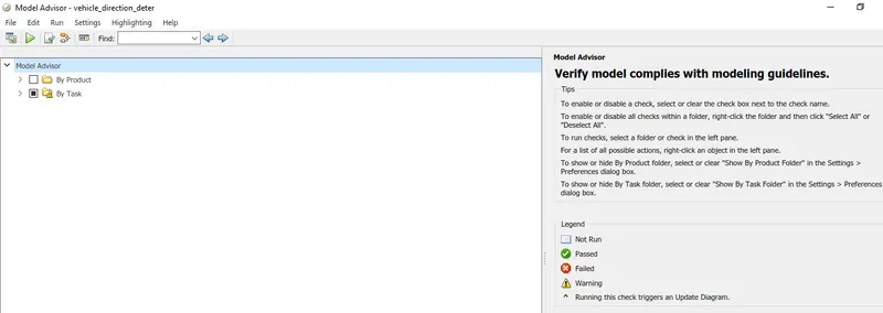
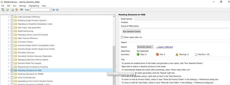
- under By Task, select only Modeling standards for MAB
- then select Run selected checks
- after running selected checks and reducing the warnings
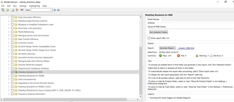
- then select generate report
- we can see that 134 passed from the total of 141 with 7 warnings from the run summary
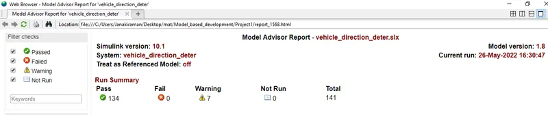
- the model advisor report has been generated.
CODE GENERATION
- for generating C code, Goto apps -- embedded coder

- then select build option and the C code will be generated.
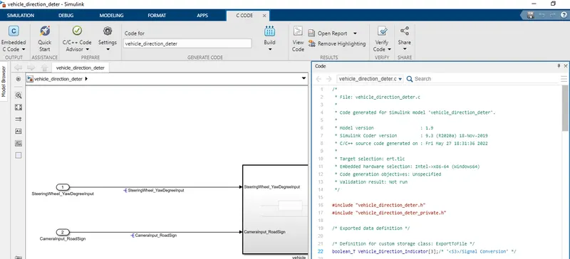
Generated C code
/*
 * File: vehicle_direction_deter.c
 *
 * Code generated for Simulink model 'vehicle_direction_deter'.
 *
 * Model version                  : 1.9
 * Simulink Coder version         : 9.3 (R2020a) 18-Nov-2019
 * C/C++ source code generated on : Fri May 27 18:31:36 2022
 *
 * Target selection: ert.tlc
 * Embedded hardware selection: Intel->x86-64 (Windows64)
 * Code generation objectives: Unspecified
 * Validation result: Not run
 */

#include "vehicle_direction_deter.h"
#include "vehicle_direction_deter_private.h"

/* Exported data definition */

/* Definition for custom storage class: ExportToFile */
boolean_T Vehicle_Direction_Indicator[3];/* '<S3>/Signal Conversion' */

/* Const memory section */
/* Definition for custom storage class: Const */
const int16_T LeftTurn_RoadSign = -120;/* Referenced by: '<S3>/Constant1' */
const int16_T Left_Turn_AngularLimit = -120;/* Referenced by: '<S2>/Constant1' */
const int16_T RightTurn_RoadSign = 30; /* Referenced by: '<S3>/Constant' */
const int16_T Right_Turn_AngularLimit = 30;/* Referenced by: '<S2>/Constant' */
const int16_T Straight_Drive_Steering_Angle = 0;/* Referenced by: '<S2>/Constant2' */
const int16_T Straight_RoadSign = 0;   /* Referenced by: '<S3>/Constant2' */

/* Real-time model */
RT_MODEL_vehicle_direction_de_T vehicle_direction_deter_M_;
RT_MODEL_vehicle_direction_de_T *const vehicle_direction_deter_M =
  &vehicle_direction_deter_M_;

/* Model step function */
void vehicle_direction_deter_step(void)
{
  /* local block i/o variables */
  int16_T Vehicle_Turn_Status;

  /* Outputs for Atomic SubSystem: '<Root>/vehicle_direction' */
  /* Switch: '<S2>/Switch' incorporates:
   *  Constant: '<S2>/Constant'
   *  Constant: '<S2>/Constant1'
   *  Constant: '<S4>/Constant'
   *  Constant: '<S5>/Constant'
   *  Inport: '<Root>/SteeringWheel_YawDegreeInput'
   *  RelationalOperator: '<S4>/Compare'
   *  RelationalOperator: '<S5>/Compare'
   *  Switch: '<S2>/Switch1'
   */
  if (SteeringWheel_YawDegreeInput > 0) {
    Vehicle_Turn_Status = Right_Turn_AngularLimit;
  } else if (SteeringWheel_YawDegreeInput == 0) {
    /* Switch: '<S2>/Switch1' incorporates:
     *  Constant: '<S2>/Constant2'
     */
    Vehicle_Turn_Status = Straight_Drive_Steering_Angle;
  } else {
    Vehicle_Turn_Status = Left_Turn_AngularLimit;
  }

  /* End of Switch: '<S2>/Switch' */

  /* SignalConversion: '<S3>/Signal Conversion' incorporates:
   *  Constant: '<S3>/Constant'
   *  Constant: '<S3>/Constant1'
   *  Constant: '<S3>/Constant2'
   *  Inport: '<Root>/CameraInput_RoadSign'
   *  Logic: '<S3>/AND'
   *  Logic: '<S3>/AND1'
   *  Logic: '<S3>/AND2'
   *  RelationalOperator: '<S3>/Relational Operator'
   *  RelationalOperator: '<S3>/Relational Operator1'
   *  RelationalOperator: '<S3>/Relational Operator2'
   */
  Vehicle_Direction_Indicator[0] = (CameraInput_RoadSign && (Vehicle_Turn_Status
    == RightTurn_RoadSign));
  Vehicle_Direction_Indicator[1] = (CameraInput_RoadSign && (Vehicle_Turn_Status
    == LeftTurn_RoadSign));
  Vehicle_Direction_Indicator[2] = (CameraInput_RoadSign && (Vehicle_Turn_Status
    == Straight_RoadSign));

  /* End of Outputs for SubSystem: '<Root>/vehicle_direction' */
}

/* Model initialize function */
void vehicle_direction_deter_initialize(void)
{
  /* (no initialization code required) */
}

/* Model terminate function */
void vehicle_direction_deter_terminate
(void)
{
  /* (no terminate code required) */
}

/*
 * File trailer for generated code.
 *
 * [EOF]
 */
Additionally performed MIL and SIL for understanding (OPTIONAL)
Model-in-Loop
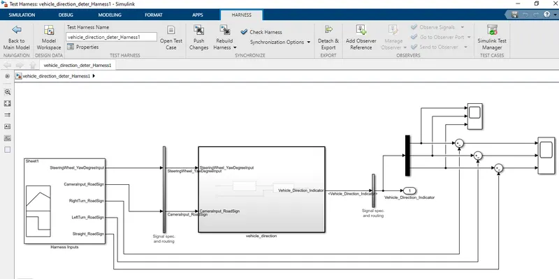
- In the MIL test, all the model blocks are tested.
- we are creating the test cases after analyzing the model behavior
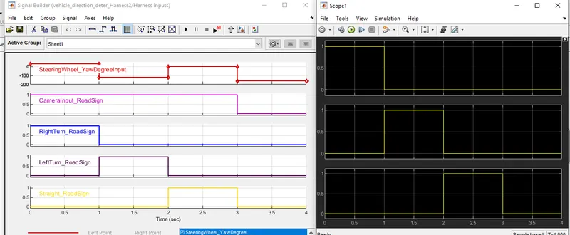
- these test cases are imported into the signal builder of created MIL test harness and the output is verified.
test cases:
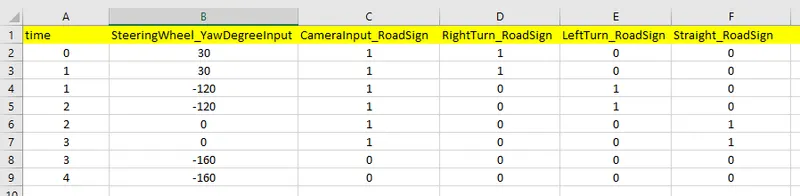
Imported into Signal builder
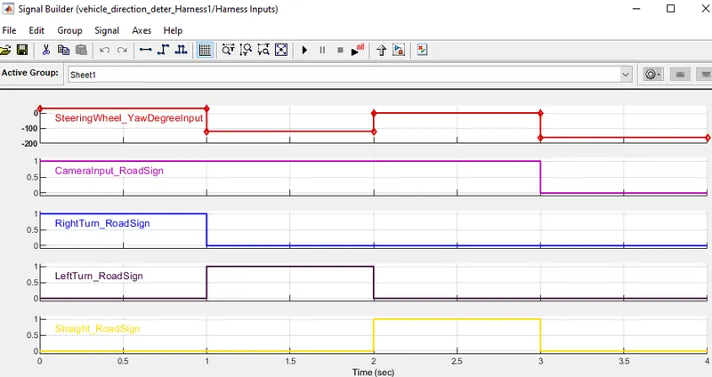
Simulink Test harness model (MIL)
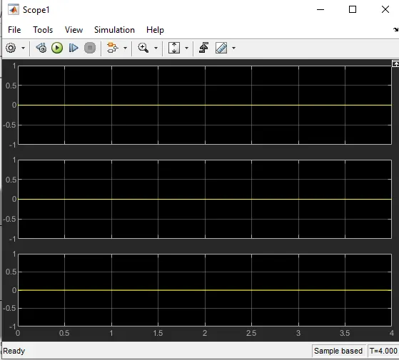
Results
1. outputs - inputs = 0
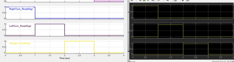
2. the inputs right-turn road sign, left-turn road sign, and straight road sign match with the outputs at the time(sec)
Software-in- Loop
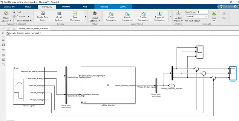
- In the SIL test, all the model blocks are converted into C code and then tested.
- we are creating the test cases after analyzing the model behavior
- these test cases are imported into the signal builder of created MIL test harness and the output is verified.
- the same test cases of MIL are used for SIL
Simulink Test harness model (SIL)
Results
1. outputs - inputs = 0
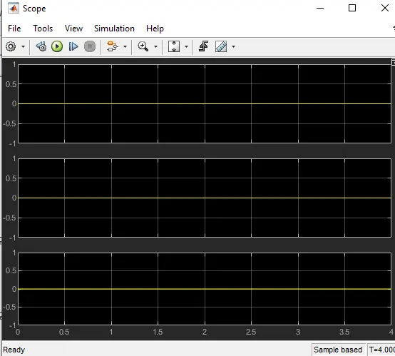
2. the inputs right-turn road sign, left-turn road sign, and straight road sign match with the outputs at the time(sec)
RESULT
- Thus a MATLAB Simulink model of Vehicle Direction Determination is successfully developed under MBD guidelines. the Data Dictionary creation, Requirements tagging, Model Advisor Report, and code generation are performed. additionally, the MIL and SIL test is performed for understanding.