Project 1 (Mini Project on Vehicle Direction Detection
Aim:
To identify the vehicle's direction in Autonomous driving & Advanced Driver Assistance Features and develop the MATLAB Simulink model as per requirement.
Objective:
- The objective of the project is to create a Simulink model for vehicle direction detection as per the requirement.
- Tag the requirements to the Simulink model; Requirement 1 & Requirement 2 are tagged to their corresponding subsystem.
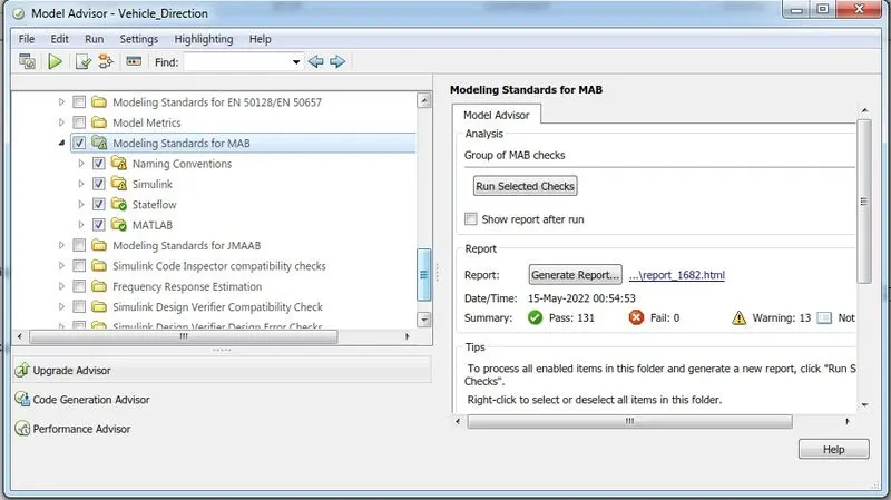
- MBD compliant changes, Data Dictionary creation & code generation is added advantage, and that is not the scope of this project.
Task:
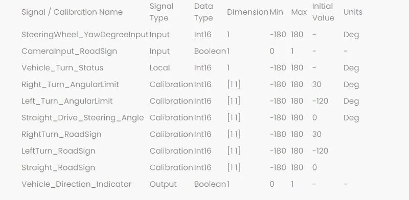
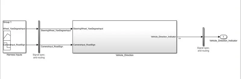
The inputs to the system are the steering wheel angular input given as yaw rate(Signal name: SteeringWheel_YawDegreeInput) and an input signal from the camera (Signal Name: CameraInput_RoadSign), which confirms the occurrence of a road sign.
A camera reads the road signs & stores them in its memory unique value for the left turn, right turn & straight drive. Depending on the direction the vehicle takes, a final indication is given to the driver- if he is driving in the recommended direction or not.
The output of the system is a boolean value (Signal Name: Vehicle_Direction_Indicator) which specifies whether the vehicle is turning right, left, or going straight.
Development Of the Simulink Model:
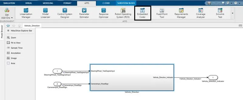
The main subsystem 'Vehicle_Direction' along with inputs 'SteeringWheel_YawDegreeInput', ' CameraInput_RoadSign', and output signal 'Vehicle_Direction_Indicator' is shown below:
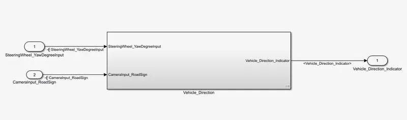
Fig 1: 'Vehicle_Direction' subsystem
The main subsystem 'Vehicle_Direction' is further divided into two more subsystems which are 'Requirement1' and 'Requirement2' as shown below:
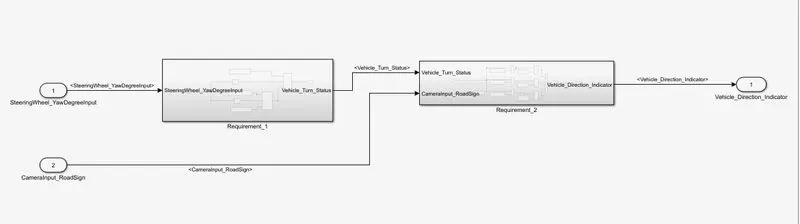
Fig 2: 'Requirement 1' and 'Requirement2' Subsystems
Requirement 1:
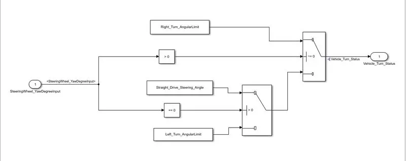
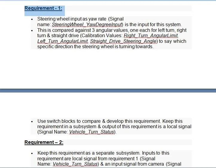
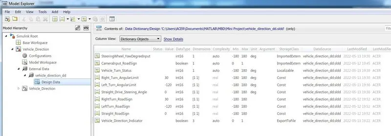
- In the 'Requirement1' subsystem, the steering wheel yaw degree (Signal name:'SteeringWheel_YawDegreeInput') is fed as input to the subsystem, and this value is compared against 3 angular values, one each for a left turn, right turn & straight drive (Calibration values: Right_Turn_AngularLimit, Left_Turn_AngularLimit, Straight_Drive_Steering_Angle) to say which specific direction the steering wheel is turning towards.
- The input signal 'Steering Wheel YawDegreeInput' is compared against three angular values using the relational operator', one each for left turn, right turn & straight drive (Calibration Values: Right Turn_AngularLimit, Left_Turn_AngularLimit, Straight_Drive_Steering_Angle) to say which specific direction the steering wheel is turning towards. In this case, the output of the relational operator'' is equal to 1 only when the 'Steering Wheel_YawDegreeInput' matches the calibration value angular limit specified in Right_Turn_AngularLimit, Left_Turn_AngularLimit, or Straight_Drive Steering_Angle.
- Three switch blocks are used to implement an if-else logic. The output from each relational operator is given as a condition input (input2) to each Switch block. The switch will pass input1 (calibration value) when the condition (input2~0) condition is satisfied, else input3 (output from the next switch block) is passed as output.
- The signal 'Vehicle_Turn_Status' obtained at the output of the first switch will be a calibration angular value (Right_Turn_AngularLimit OR Left_Turn_AngularLimit, OR Straight_Drive_Steering Angle). If none of the conditions get satisfied, zero is passed as the output from the last switch. The signal 'Vehicle_Turn_Status' is fed to the outport of subsystem 'Requirement1'.
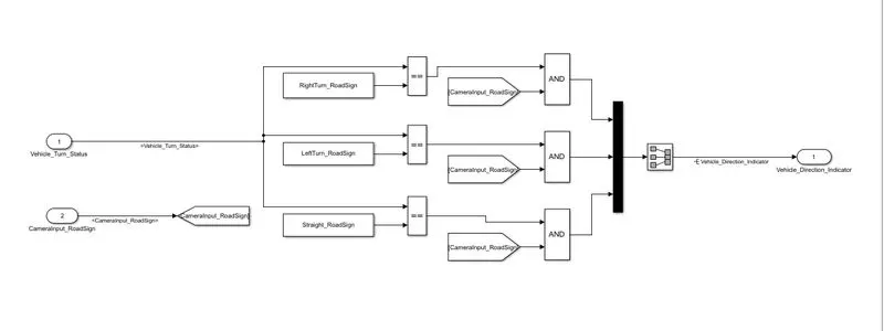
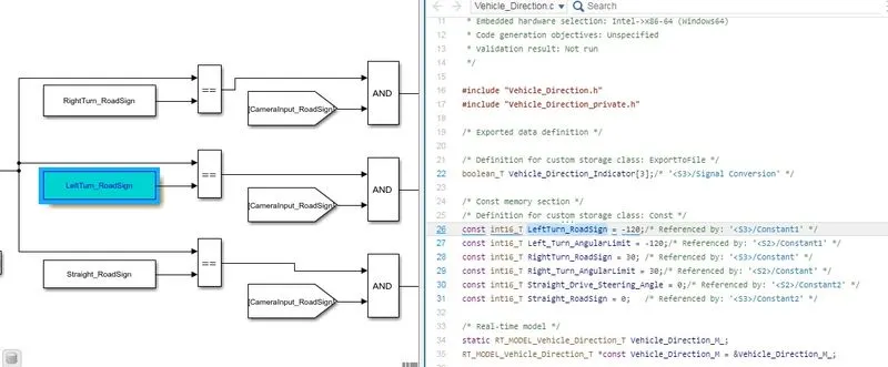
- In the 'Requirement2' subsystem, the local signal Vehicle Turn Status' fed from the 'Requirement1' subsystem is taken as input and is compared against calibration values (Right Turn RoadSign, LeftTurn_RoadSign, Straight_RoadSign) using the relational operator'=='
- The boolean value obtained at the output of the relational operator is compared against a boolean input signal from the camera (Signal Name: CameraInput_RoadSign), which confirms the occurrence of a road sign using 'AND' operator.
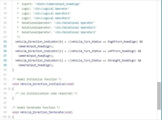
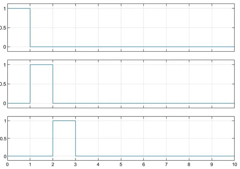
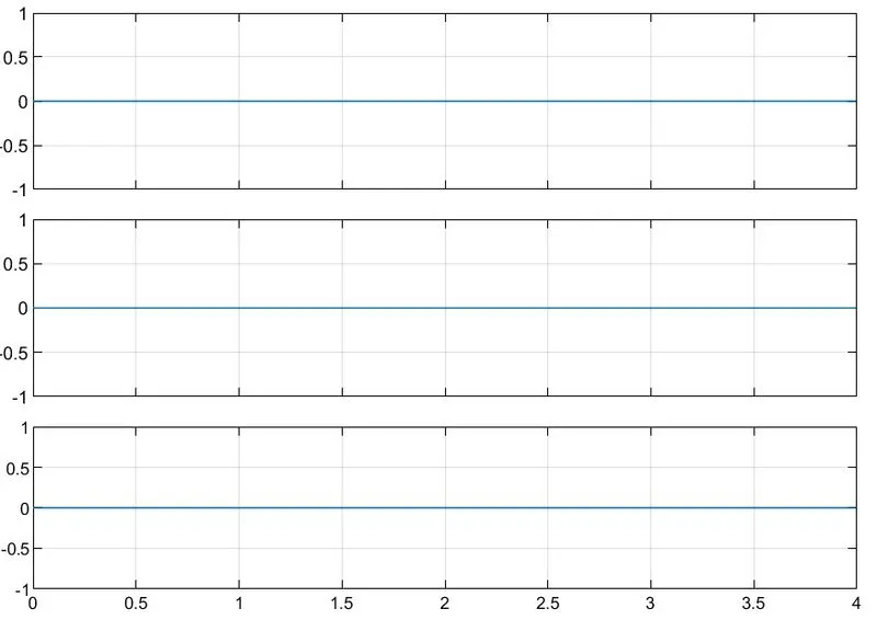
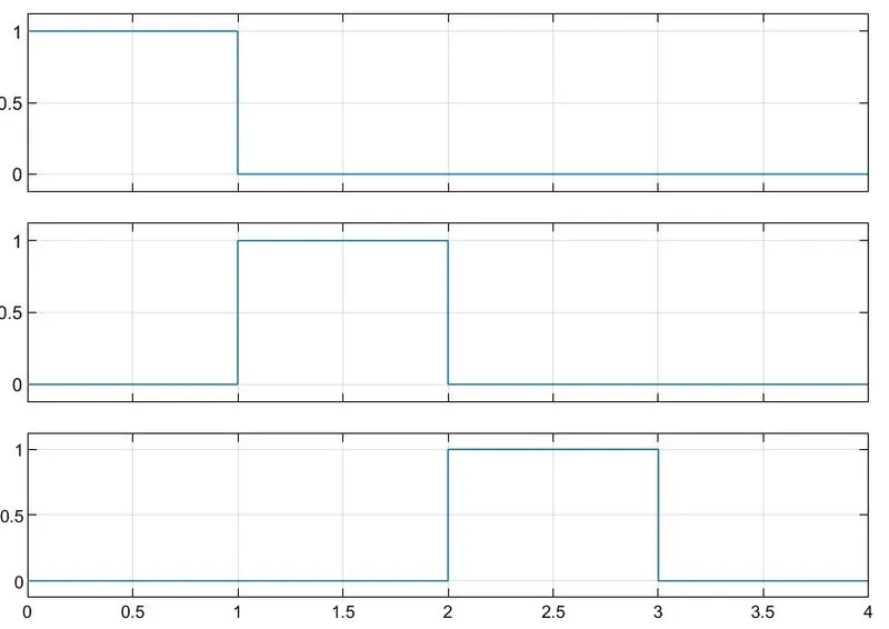
- The boolean output signal obtained from each of the three 'AND' blocks is fed to the outport 'Vehicle Direction_Indicator' to indicate the vehicle direction. The output 'Vehicle Direction_Indicator' will be a three-dimension signal having three boolean elements, with the first element to indicate 'Right Turn', the second element to indicate 'Left Turn', and the third element to indicate 'Straight Drive'.
- The requirements 'Requirement-l' and 'Requirement-2' as provided in the Requirements Word document are tagged to their corresponding subsystem in the Simulink Model.
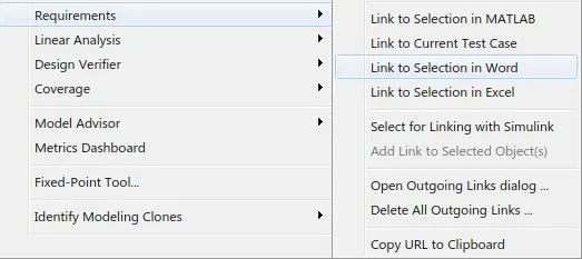
- The steps involved in tagging a requirement in the Simulink model are to first highlight the requirement stated in the Word document, then right-click on the subsystem in the model that has to be tagged, then select 'Requirements and then 'Link to Selection in Word'.
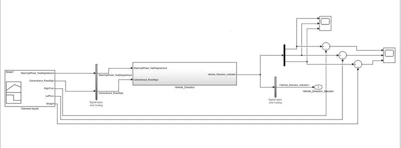
- The MATLAB Simulink model has been developed as per requirement.
- Tagging of requirement 1 & requirement 2 has been done to their corresponding subsystems.
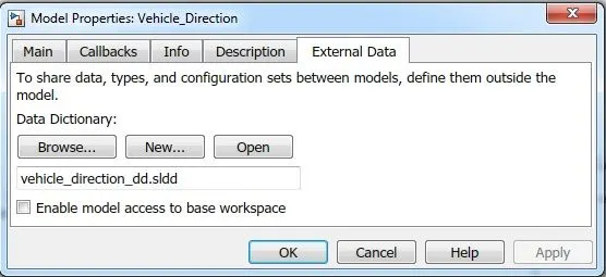
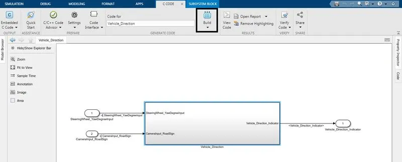
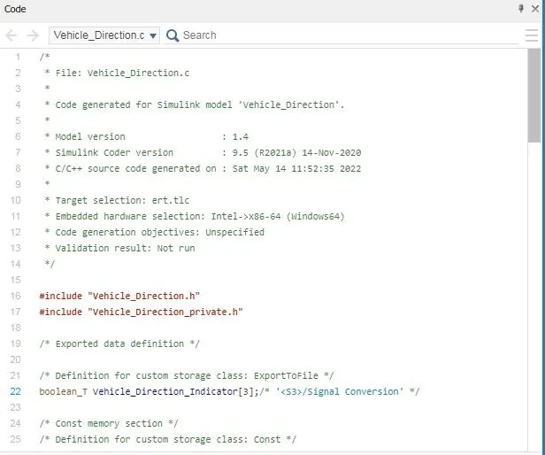
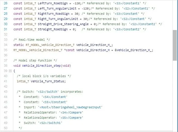
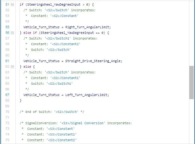
- Data Dictionary has been created & the code has also been generated.
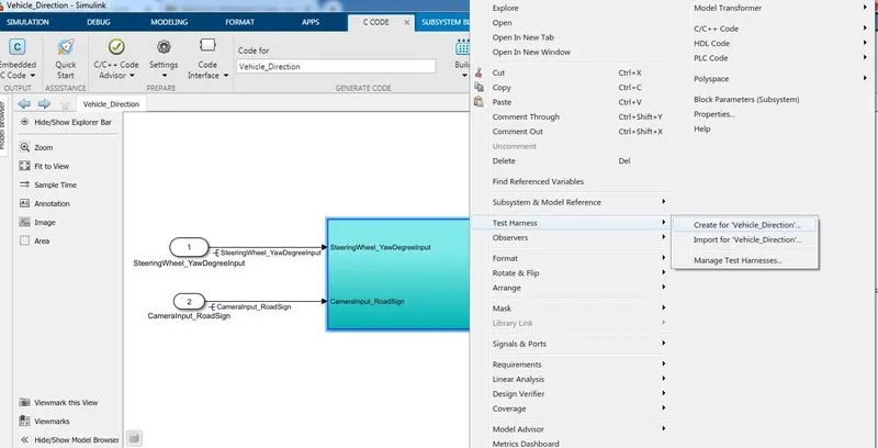
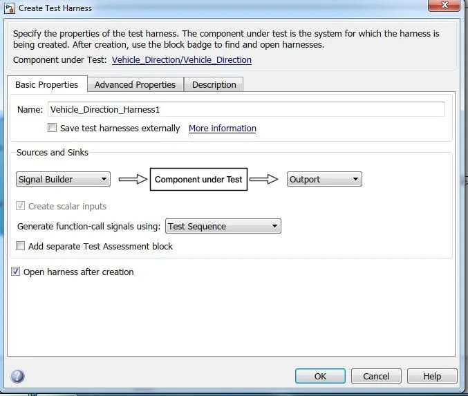
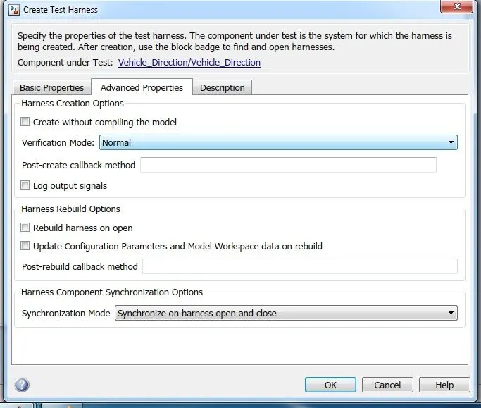
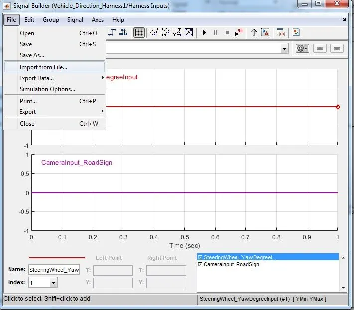
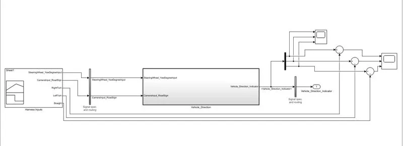
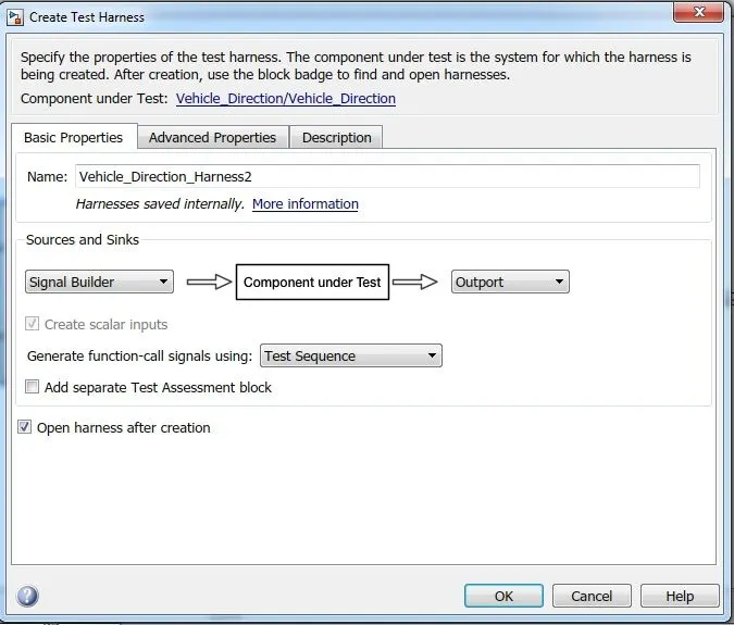
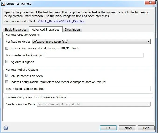
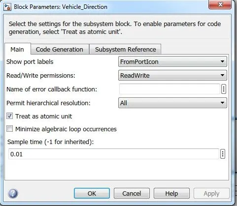
- In addition, we also created a MIL test and SIL test.