Project 1 (Mini Project on Vehicle Direction Detection
Project 1 (Mini Project on Vehicle Direction Detection)
Objective of Mini Project:
- Development of MATLAB Simulink model as per requirement.
- Tag the requirements to the simulink model; tagging requirement 1 & requirement 2 to their corresponding subsystems is fine.
- MBD compliant changes, Data Dictionary creation & code generation is added advantage, and that is not scope of this project.
- If choosing code generation, Storage class for Input signals: ImportedExtern; Storage class for Output signal: Export to File; Storage class for local signals: localizable; Storage class for calibration signals: Const.
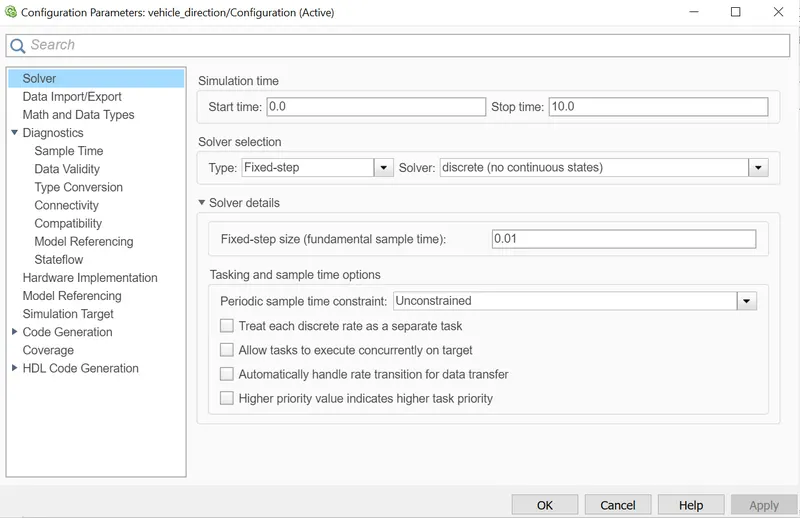
- Choose sample time for all signals as 0.01s
Task:
- The inputs to the system are the Steering wheel angular input given as yaw rate and an input signal from camera-camera input roadsign which confirms the occurrence of a road sign.
- Camera reads the road sign and stores into its memory unique values for left turn, right turn or stationary movement. The output of system is a boolean value.
Create SLDD file:
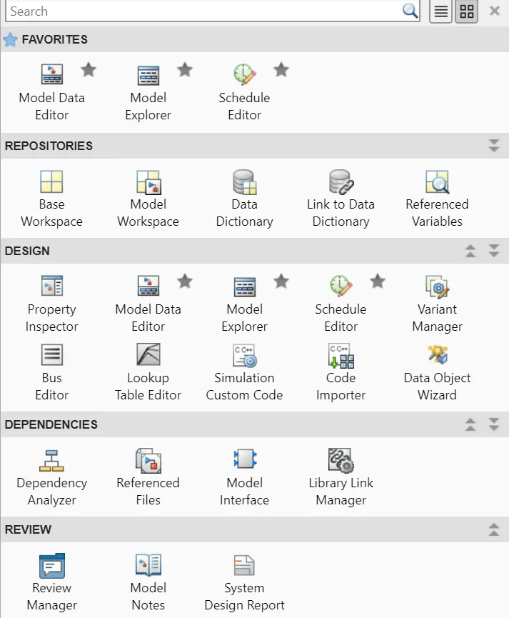
- Click on modeling--link to data dictionary--browse and select--ok.
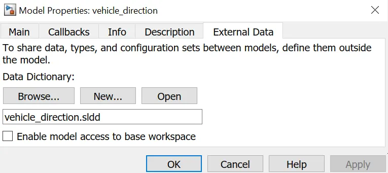
- Create SLDD file with the given datas:
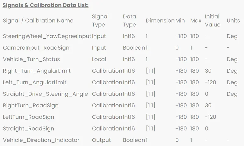
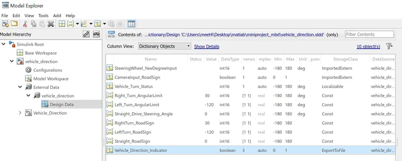
Development of Simulink Model:
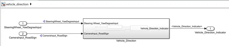
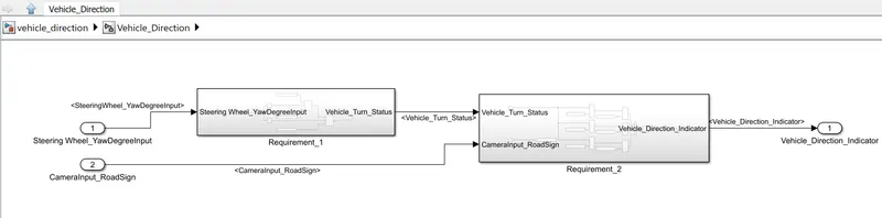
- Vehicle direction subsystem: The main subsystem is again divided to 2 more subsystems which are Requirement 1 and Requirement 2.
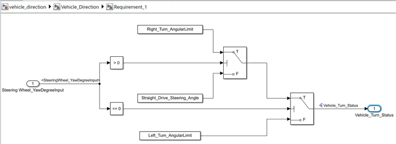
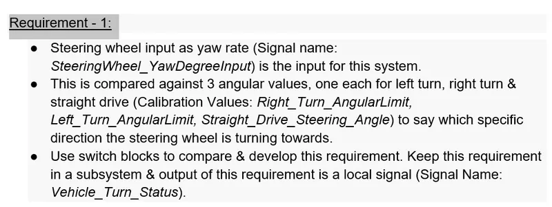
- Requirement 1 subsystem: Here we are trying to determine which direction the steering wheel is turning right or left. Minimum and maximum values of rotation of steering wheel is -180 deg and 180 deg. So we need to compare this value with 3 constant values. If value greater than 0 then right turn then 30, if equal to zero then straight driving. If value less than 0 then left turn.
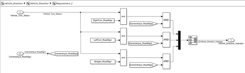
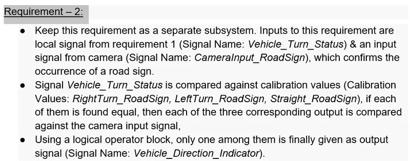
- Requirement 2 subsystem: Here the output is boolean ie 0 or 1. Dimension of output should be 3 because its connected to mux as shown in figure. This boolean output from 3 AND blocks are fed to outport to indicate the vehicle direction.
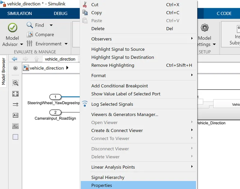
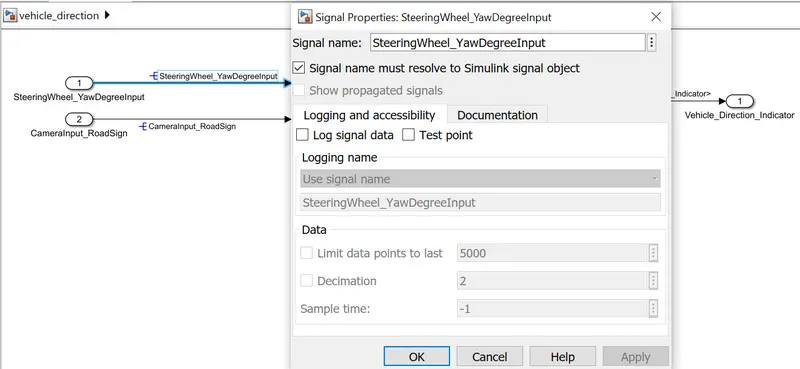
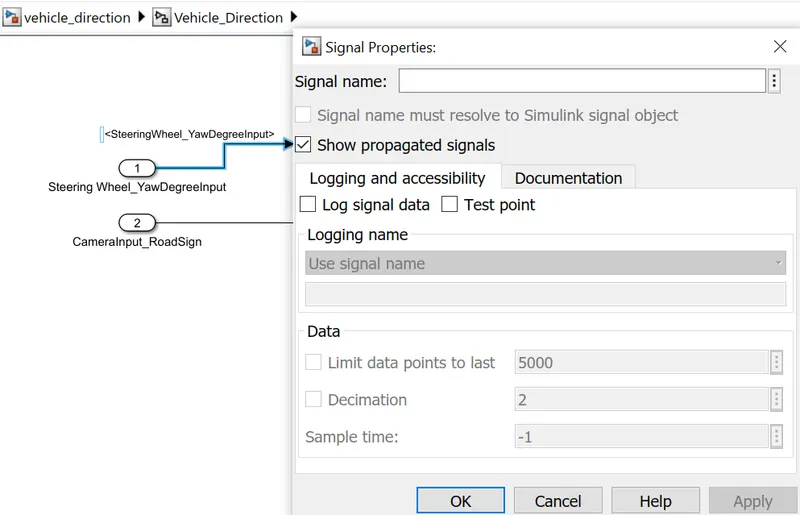
Resolving and Propogating signal: Right click on model select properties, for the signal appearing first time give corresponding the signal name and resolve it. For signal appearing second time in model select on propagate signal option.
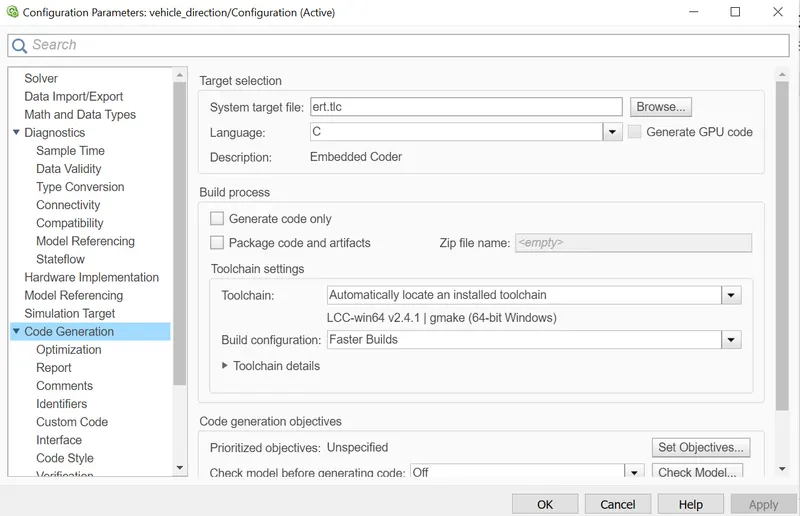
Simulink Model setting: Solver and code generation
Requirement Tagging:
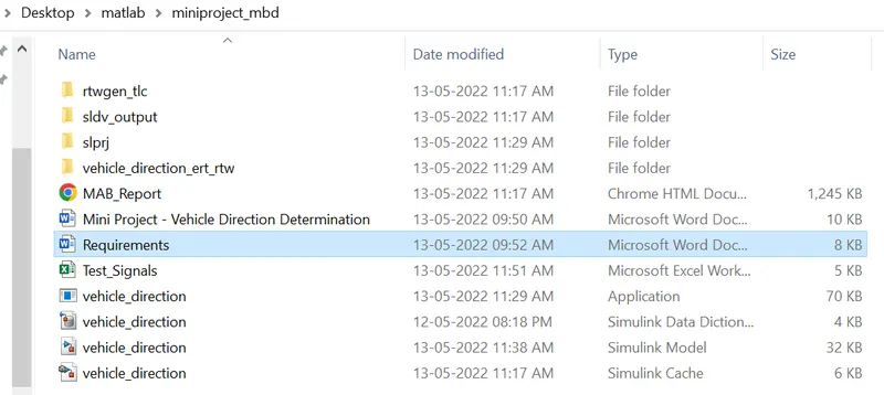
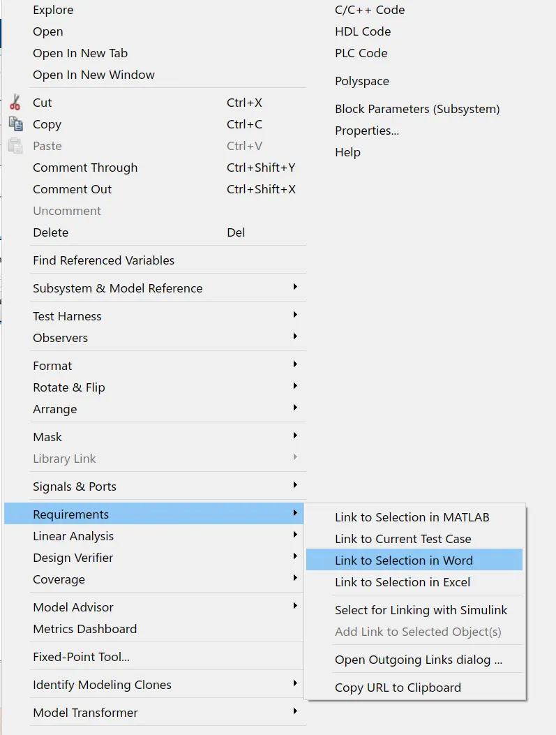
Requirement 1 and 2 are provided as word documents and are saved in the working folder. It is tagged to their corresponding subsystem in model. First select the requirement 1 heading and highlight it and then go to model -- right click-- select requirements-- link to selection in word.
Check for Modeling Standards:
MAB (Mathworks Advisory Board): The MAB Guidelines are a set of modeling guidelines developed by an independent industry working group for the usage of MATLAB®, Simulink®, Stateflow® and Embedded Coder®. The guidelines are the culmination of years of engineering expertise and best practices for developing, maintaining and documenting control algorithm models used in the development of production software.
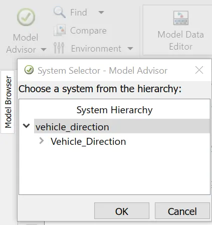
- Go to model advisor--choose system--select modeling standard for MAB
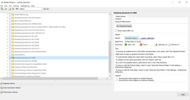
- Tick on modeling standard for MAB and run selected checks.
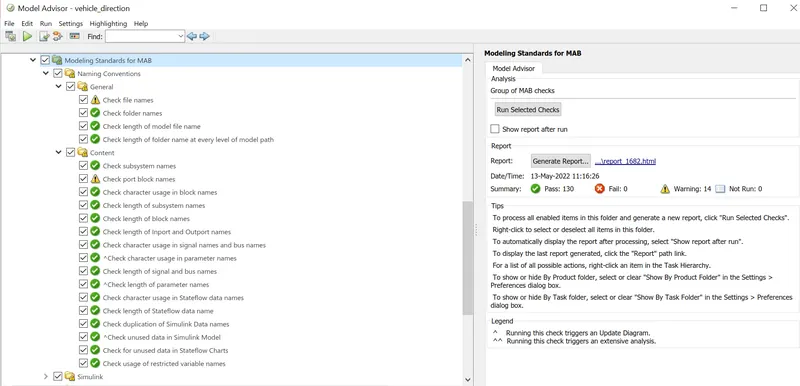
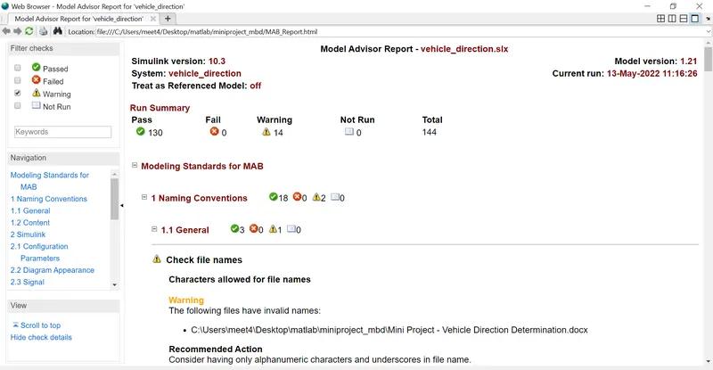
- Model advisor report : It shows that there is no failed test cases.
- Now finally download the report by clicking on generate report option.
Code generation:
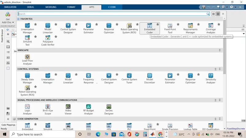
- Now to generate code click on Apps-- Select embedded coder.
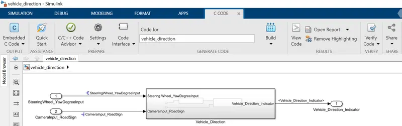
- Now select on build option.
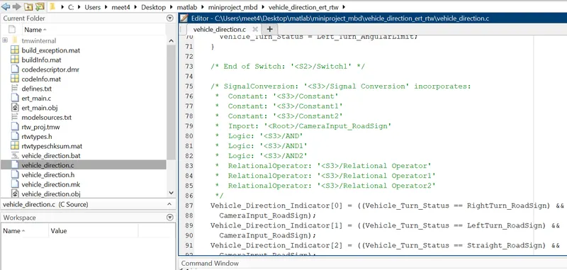
- Vehicle direction code is generated as shown .
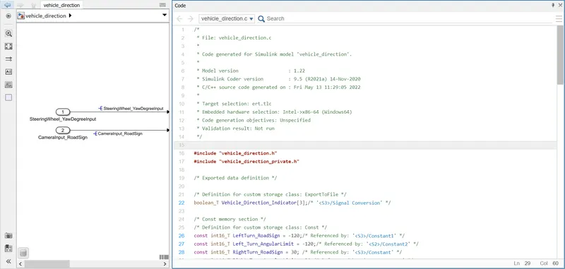
- We can also access the code from current folder.
Steps for MIL Test:
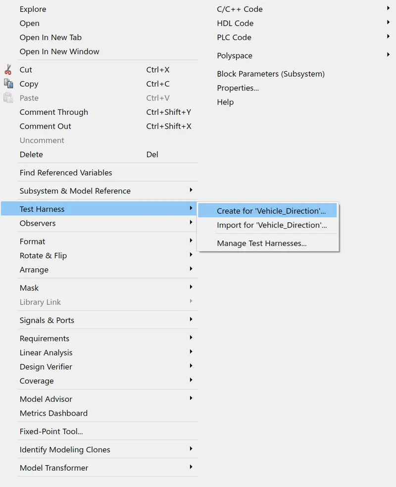
- Right click on model-- Select test harness-- create for 'option'.
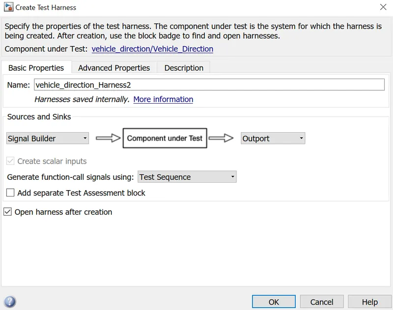
- For MIL test select inport as Signal builder block and outport remains as default.
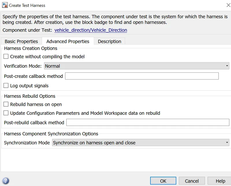
- Inside advanced properties keep verification mode as normal.
- Vehicle direction harness model will appear.
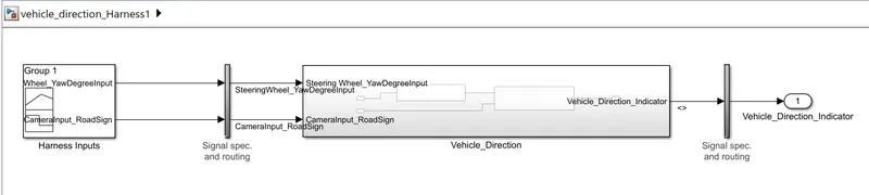
- Click on signal builder block.
- Click on file option--Select import from file option--Now browse and select the file and the required options as shown in the image below and give confirm and ok.
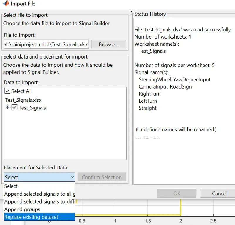
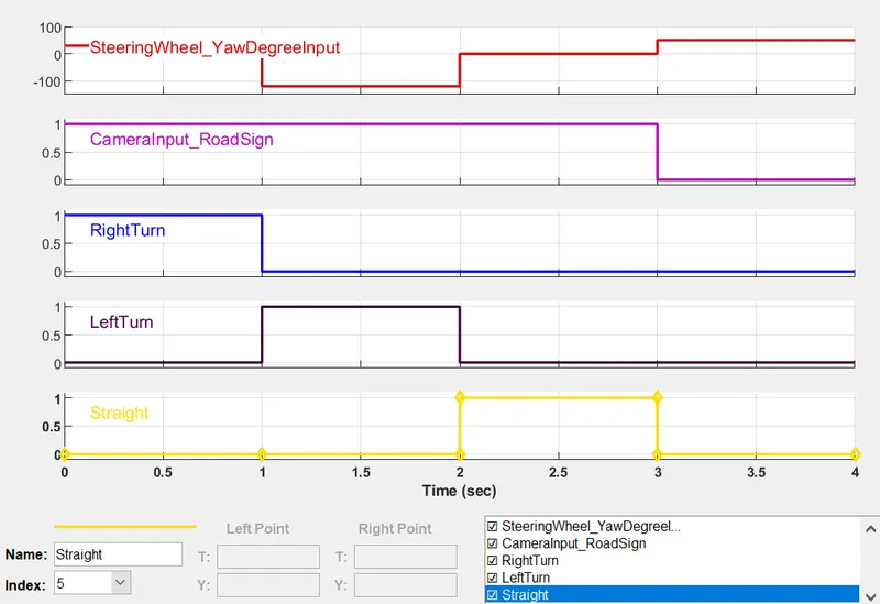
- Signal builder input:
- Now connect the end side with demux to get the output for 3 signals initially connected to the mux and connect it with scope to get the digfference between actual signal and expected signal.
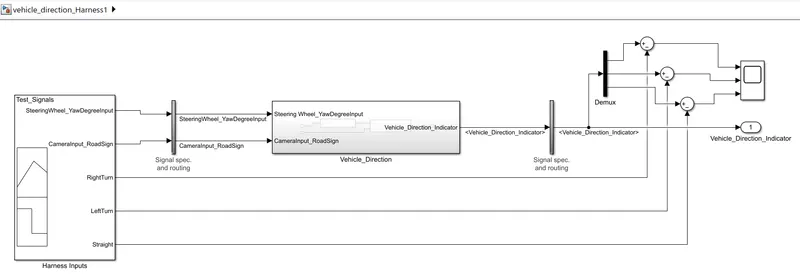
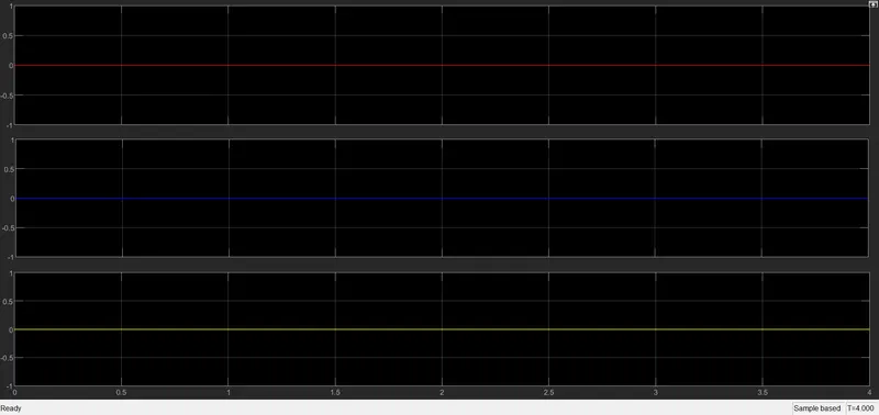
- Resultant waveform says that actual signal and the expected signal are same and there is no difference between them.
Steps for SIL Test:
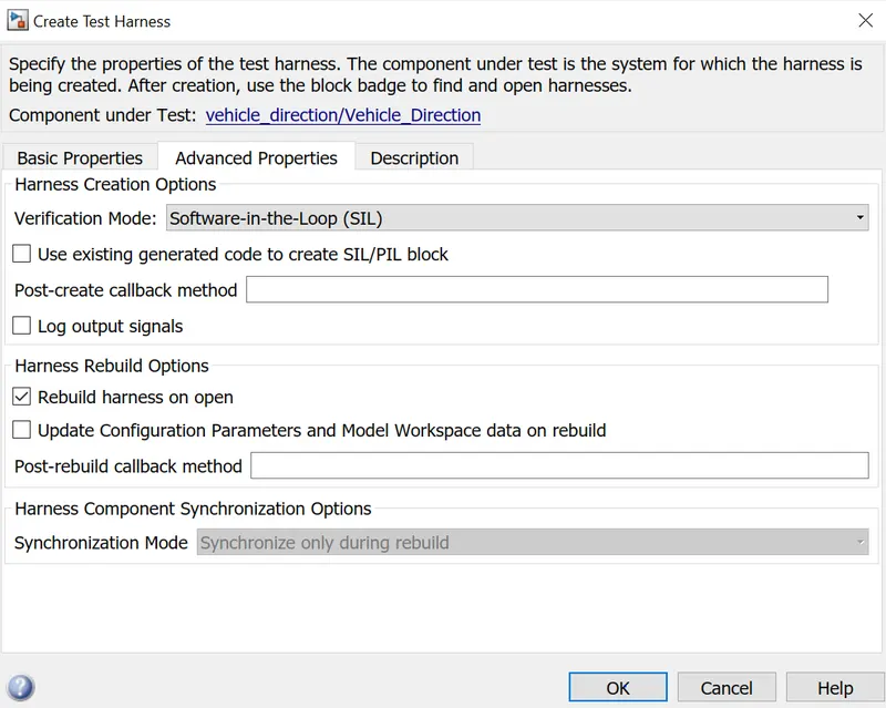
- Right click on model-- Select test harness-- create for 'option'.
- For SIL test select inport as Signal builder block and outport remains as default.
- Inside advanced properties keep verification mode as SIL.
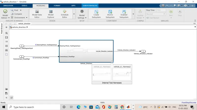
- Vehicle direction harness model will appear.
- Click on signal builder block.
- Click on file option--Select import from file option--Now browse and select the file and the required options as shown in the image below and give confirm and ok.
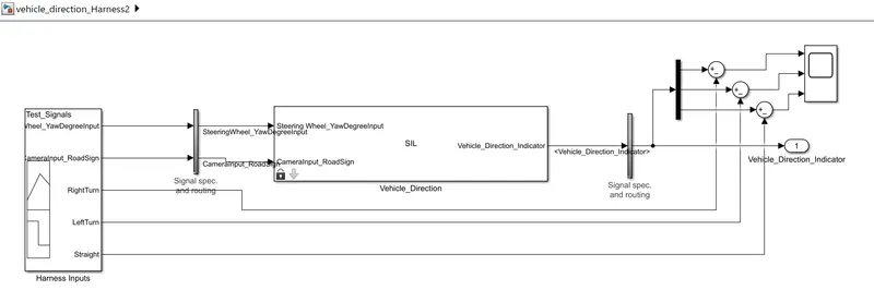
- Now connect the end side with demux to get the output for 3 signals initially connected to the mux and connect it with scope to get the digfference between actual signal and expected signal.
- Signal builder input:
- Resultant waveform says that actual signal and the expected signal are same and there is no difference between them.