Project 1 (Mini Project on Vehicle Direction Detection
Solution-
Aim Of Project:-
- Development of MATLAB Simulink model as per requirement.
- Tag the requirements to the simulink model; tagging requirement 1 & requirement 2 to their corresponding subsystems.
- Creation of SLDD File
- Check for MAB guidelines
- Code generation
Description-
Creation of SLDD FILE-
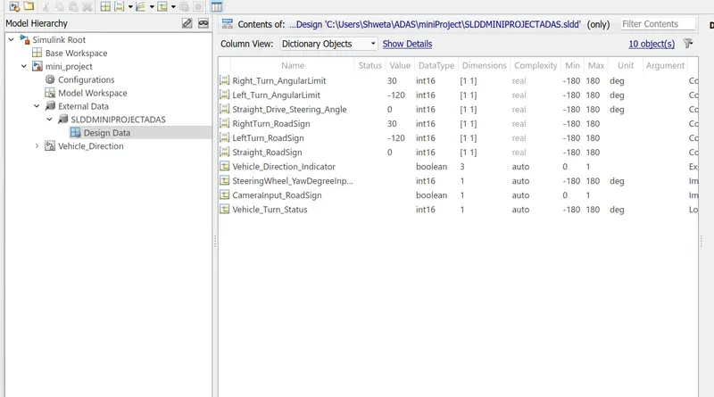
- Data has been given to create a SLDD file.
- With the use of following data given, I've created a sldd file.
- File Created is as shown in the below figure.
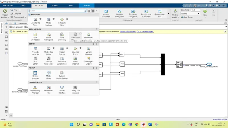
To create the SLDD file, we clicked on modelling tab>drop down menu>select link to data dictionary-
Then we can add all the data given to us one by one as shown in the very first figure.
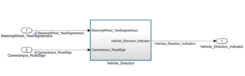
After creating the SLDD file, we created the main subsystem, as per the question there should be 2 subsystems in the main subsystem-
main(Vehicle_Direction) subsystem-
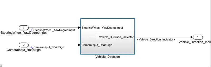
Two subsystems as Requirement1 and Requirement 2 in the main subsystem-
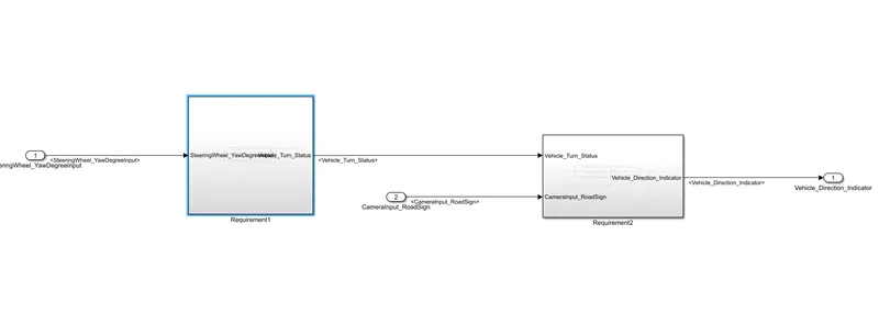
as per the descripton given in the question for Requirement 1-
Requirement - 1:
- Steering wheel input as yaw rate (Signal name: SteeringWheel_YawDegreeInput) is the input for this system.
- This is compared against 3 angular values, one each for left turn, right turn & straight drive (Calibration Values: Right_Turn_AngularLimit, Left_Turn_AngularLimit, Straight_Drive_Steering_Angle) to say which specific direction the steering wheel is turning towards.
- Use switch blocks to compare & develop this requirement. Keep this requirement in a subsystem & output of this requirement is a local signal (Signal Name: Vehicle_Turn_Status).
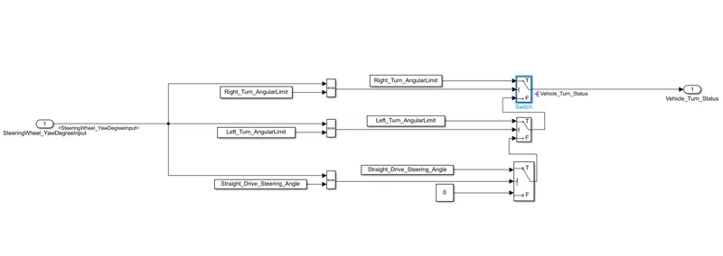
we took SteeringWheel_YawDegreeInput as input signal, as we already linked the model to SLDD, it automatically selcted the data type and values for every input or block we selected as per the given data.
In the next step we used 3 constant blocks to indicate-
Right_Turn_AngularLimit,Left_Turn_AngularLimit,Straight_Drive_Steering_Angle and compared the all three with realtional operators (==) against SteeringWheel_YawDegreeInput.
In the third step we Used switch blocks to compare and develop the output of the subsystem (Requirement1) & output of this requirement is a local signal (Signal Name: Vehicle_Turn_Status).
Requirement – 2:
- Keep this requirement as a separate subsystem. Inputs to this requirement are local signal from requirement 1 (Signal Name: Vehicle_Turn_Status) & an input signal from camera (Signal Name: CameraInput_RoadSign), which confirms the occurrence of a road sign.
- Signal Vehicle_Turn_Status is compared against calibration values (Calibration Values: RightTurn_RoadSign, LeftTurn_RoadSign, Straight_RoadSign), if each of them is found equal, then each of the three corresponding output is compared against the camera input signal,
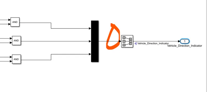
- Using a logical operator block, only one among them is finally given as output signal (Signal Name: Vehicle_Direction_Indicator).
The output of the Requirement1 was one input for the Other subsystem Reuirement2-as shown below-
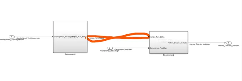
The first statement of requirement 2 is satisfied by taking 2 inputs one from tghe output of requirement one and other input was taken as an input signal from camera (Signal Name: CameraInput_RoadSign), which confirms the occurrence of a road sign, as shown below-
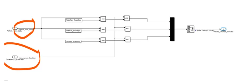
The second statement of requirement 2 was-
- Signal Vehicle_Turn_Status is compared against calibration values (Calibration Values: RightTurn_RoadSign, LeftTurn_RoadSign, Straight_RoadSign), if each of them is found equal, then each of the three corresponding output is compared against the camera input signal
To satisfy the requirement 2 we compared the calibration values by using realtional operator and then we used logical operator to compare it with camera input as shown below-
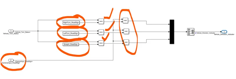
Finally Using a MUX block, only one among them is finally given as output signal (Signal Name: Vehicle_Direction_Indicator).
Final Simulink Model-
Signal Resolving and Propogation:
- Seclect the signal that has to be resolved.
- Go to Properties
- Enter signal name
- Tick resolve option
- apply and ok
Similarly, signal propogation:
- once the signal has been resolved, signal has to be propogated further.
- Siglect the signal which is to be propogated
- go to properties
- tick, Signal propogation option
- Apply and ok
when the signal is originationg for the first time, it is resolved and if it is continued, it is propogated.
Signal Tagging:
- Create a Word format of the given Requiremnts.
- Highlight Requirement-1 in the word
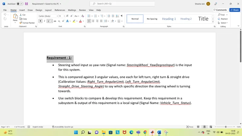
- Now open simulink model
- Open out subsystem of Requirement1
- Right click -> Requirements -> Link to selection in Word
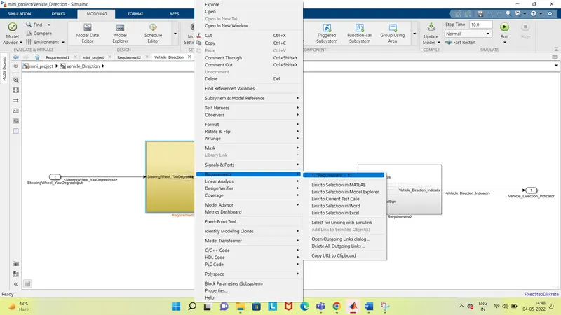
Tagging will be done for Requirement-1.
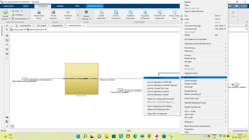
We followed the same steps for tagging of Requirement-2-
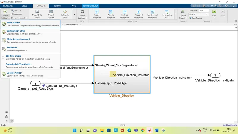
Check for MAB guidelines-
- Go to model Advisor
- Select Modelling Standards for MAB
- Run
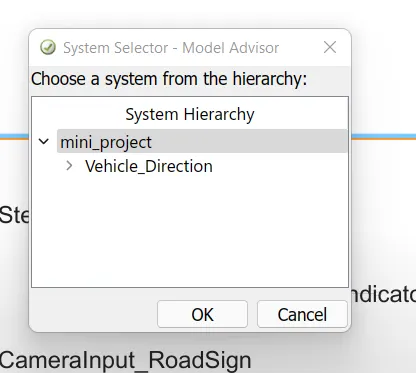
Select entire model-
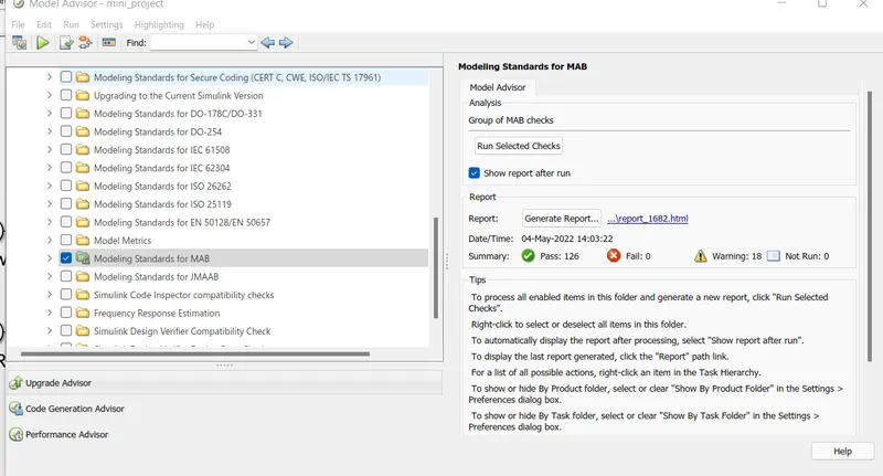
Run selected checks and there should be no failed conditions-
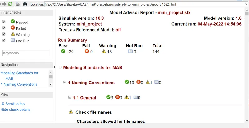
Code generation-
Solver settings-
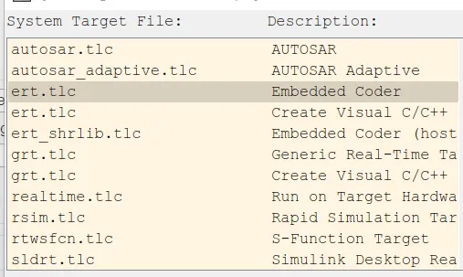
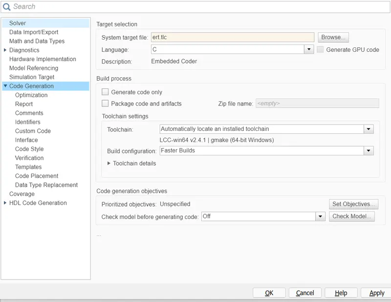
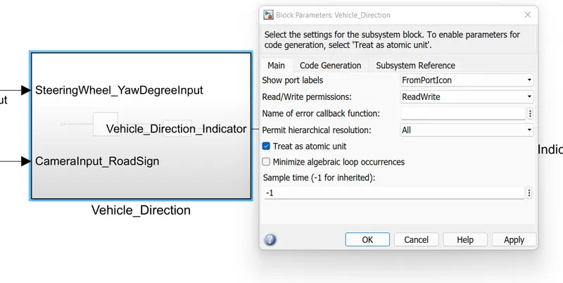
Go to block parameters of subsystem and treat as atomic unit for code generation-
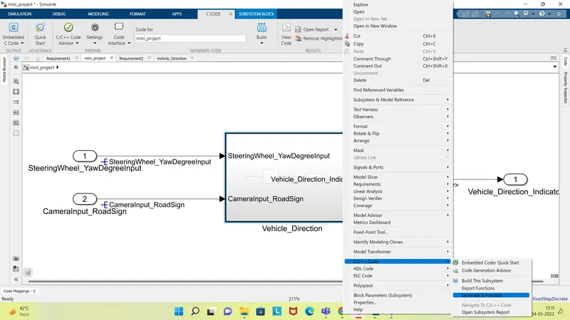
To generate S-function-
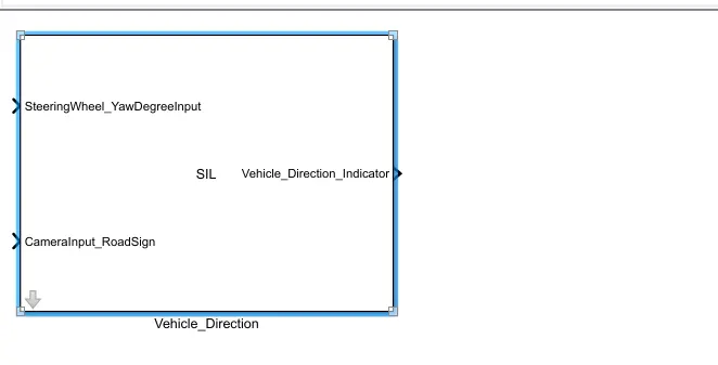
Select create SIL block-
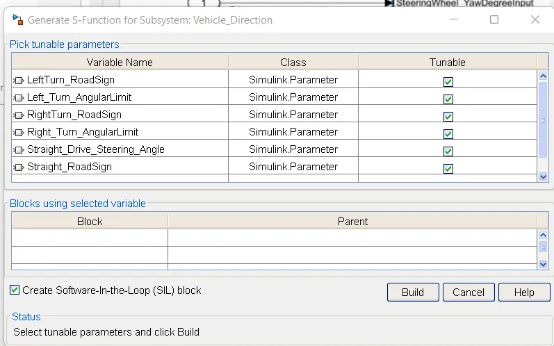
Click on Build-
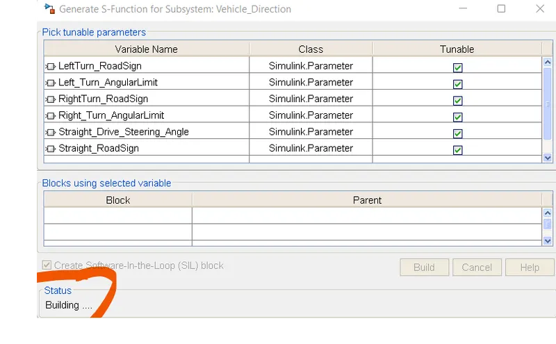
Therefore seperate SIL block will be reacted. And a code will be Generated.
A SIL block will be created-
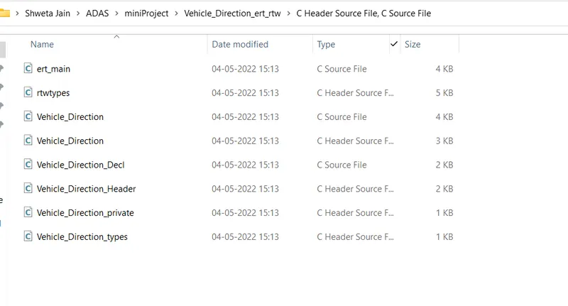
Code files-