Week -2
OBJECTIVE:-
- Make a Simulink model of Doorbell using solenoid block with the following details:
In the above arrangement, when the switch is closed the electromagnet receives electrical power from the battery and pulls the metal arm to hit the bell producing sound.
Create a situation where the switch is closed for 2 seconds and then released. Observe the physical movement of the plunger.
Assume remaining parameters.
- Use a thermistor to sense the temperature of a heater & turn on or turn off the fan as per the below conditions:
Temperature source: 20 °C from 0 to 10 seconds, 27 °C from 10 to 30 seconds, 23 °C from 30 to 50 seconds
Fan conditions: ON if the temperature above 25 °C, OFF otherwise.
Solution:-
- Principal of doorbell:- The Doorbell works on the principal of magnetic field created by the electromagnet/solenoid. When current is passed through the battery, a magnetic field is generated which attracts the plunger/metal arm to hit the bell. When it touches the metal arm the circuit breaks and it returned to its original position. Since the current is given by a battery the process repeats itself until the current flow is stopped and that’s how the doorbell works.
Simulink model:-
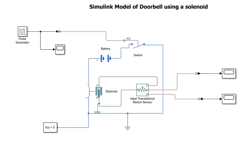
Process:- The values given to the pulse generator are as shown below:-
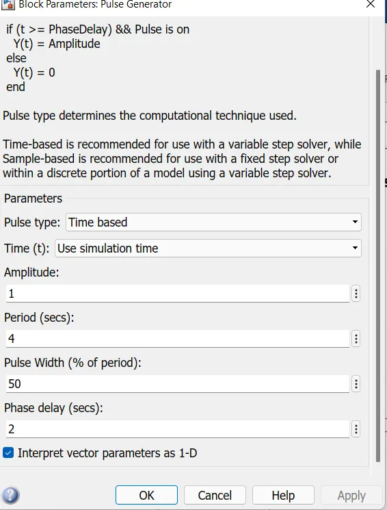
The above values are for the situation where switch is closed for 2 seconds and then released. The signal given as input is first converted into real time environment and then fed to the switch which is controlling the current through the solenoid.
The battery is connected to the switch and solenoid which is being sensed by the ideal translational motion sensor.
signals are then converted to the PS-simulink phase to observe the motion of plunger.
RESULTS:-
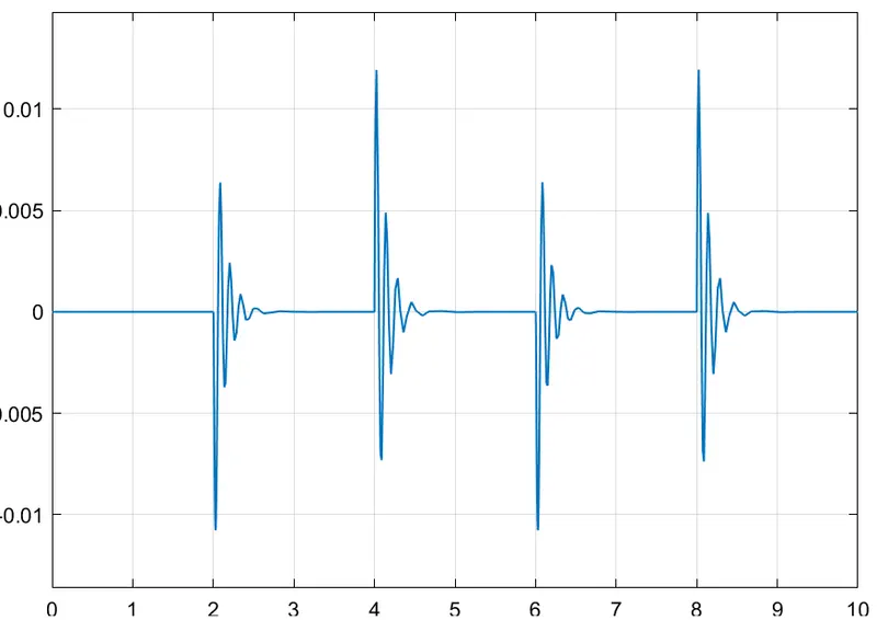
A.Velocity PLOT
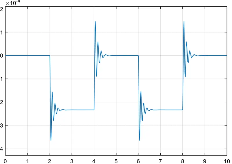
B. Position plot:- From the above plot we can observe the motion of plunger that hits the metal arm after every 2 secs.
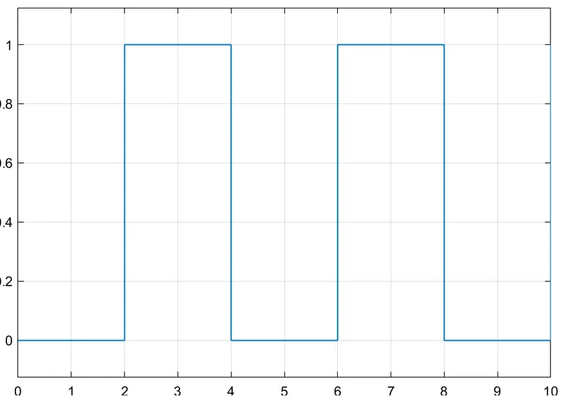
C.AMPLITUDE PLOT:- Pulse generator is generating the pulse for every 2 seconds.
2.Principal of Thermistor:-
Thermistor word consists of thermal+resistor. Which simply describes its utility- a resistor that controls the temperature. It is a type of resistor whose resistance varies with the temperature. Basically it senses/absorb the temperature hence it acts as a passive component in an electric circuit.
The working principle of a thermistor is that its resistance is dependent on its temperature.
It is made up of two or more semiconductor powders made of metallic oxides are mixed with a binder to form a slurry. we have to put it into a sintering furnace to dry it.
During this process, the slurry will shrink onto the lead wires to make an electrical connection.This processed metallic oxide is sealed by putting a glass coating on it. This glass coating gives a waterproof property to the thermistors – helping to improve their stability.
Simulink Model :-
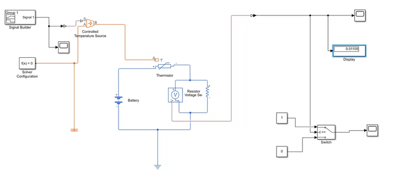
Process:-
A signal is given from the signal builder with the values as given below:-
T=293.15k(20 °C) from 0 to 10 seconds, T=300.15K(27 °C) from 10 to 30 seconds, T=296.15K(23 °C) from 30 to 50 seconds
Signal is then converted to the real time environment and fed to the controlled temperature source which is feeding to the thermistor. Thermistor senses the given temperature and generate the resistance accordingly. The thermistor used is NTC type so when the temperature rises-resistance decreases.
The thermistor is connected to a voltage sensor and a battery. A resistor is connected across the voltage sensor. the voltage is fed to the switch further to turn on the fan. switch is fed with the threshold value of 0.0128 with u2>=threshold criteria for input, to turn on the fan if the temperature above 25 °C, OFF otherwise.
RESULTS:-
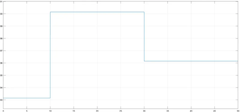
Thermal signal given by the signal builder at the pre described values.
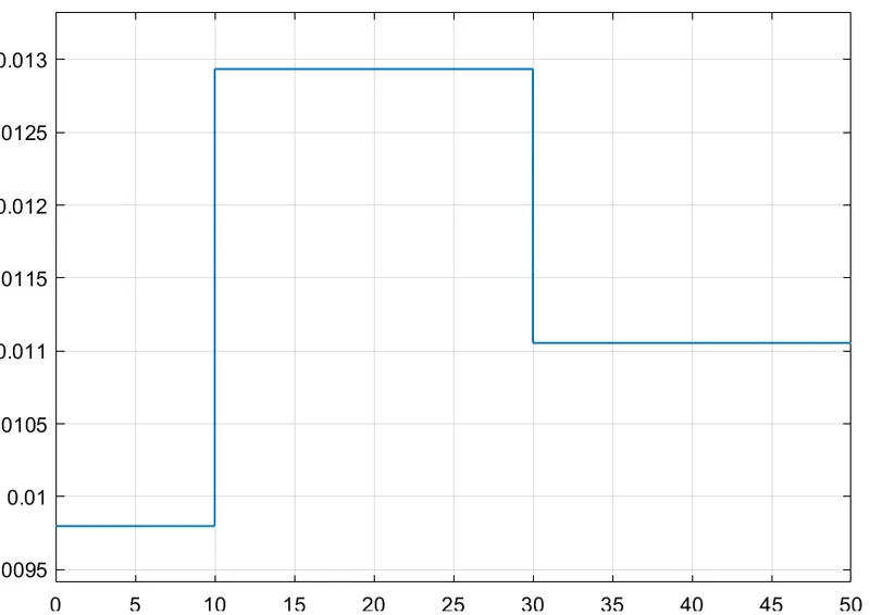
Time Vs Voltage Plot
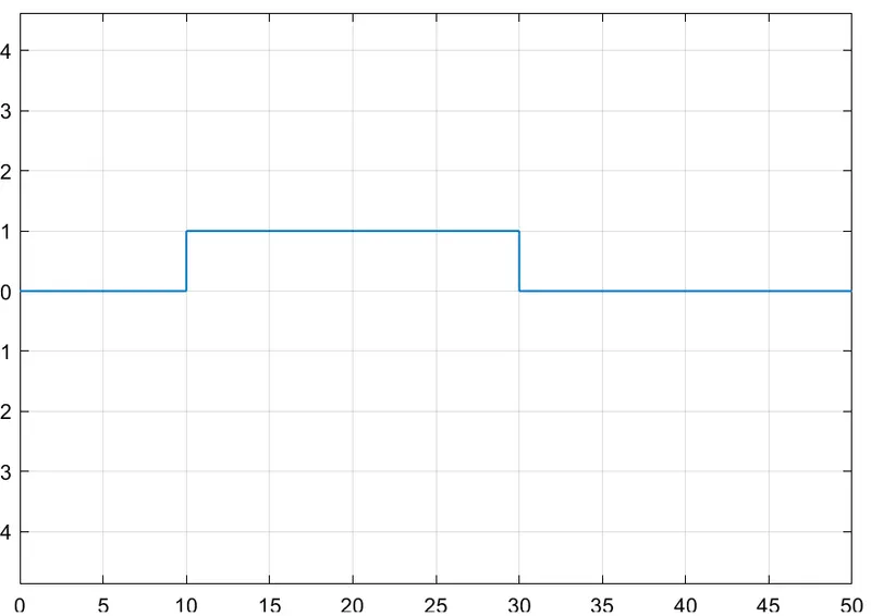
Time Vs Controlled Voltage Plot
"From above plot it is clearly seen that voltage is obtained only for 10-30 seconds at T=27 degree celcius which is above 25 degree celcius to turn on the fan at desired temperature."