Project 1 (Mini Project on Vehicle Direction Detection
Aim:
To create a model to identify the direction of vehicle by reading the road signs using camera sensor. An indication will be given to the driver if the vehicle_Turn_status and the Camera_RoadSign is different otherwise if both are matching then the driver can keep on going.
Model Explanation:
We have two requirements in this project.
Requirement-1:
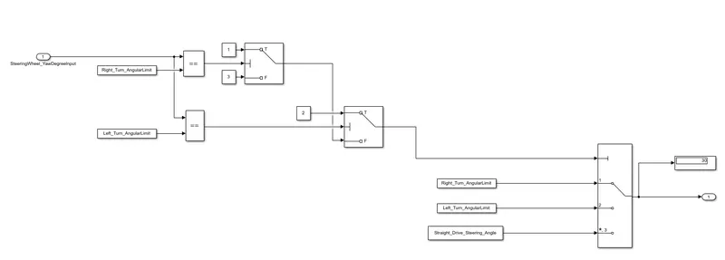
The input is steering wheel Yaw degree, which is compared with the calibration values for left_turn, Right_turn and the straight drive using the switch blocks and relational operater blocks. A multiport switch is used to determine the vehciel turn status which the output form the requirement_1 subsystem.
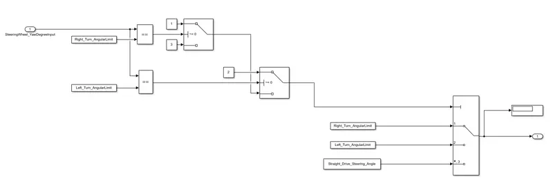
The steering wheel yaw degree input signal is compared with the calibration value Right_Turn_Angular_limit using the equal to relational operator block, Output of the same is given as a threshold to the switch block. if the condition is true then constant 1 will be the output else constant 3 will be the output.
Again the steering wheel yaw degree input signal is compared with the calibration value Left_Turn_Angular_limit using the equal to relational operator block, Output of the same is given as a threshold to the second switch block. if the condition is true then constant 2 will be the output else output signal from the first switch block will be the output here.
The output of the above logic is given as a threshold to the multiport switch block inwhich constant1, 2 & 3(default) represents Right_Turn_Angular_limit, Left_Turn_Angular_limit & Straight_drive_steering_Angle. The output of the multiport switch block represents the vehicle_Turn_Status.
Requirement-2:
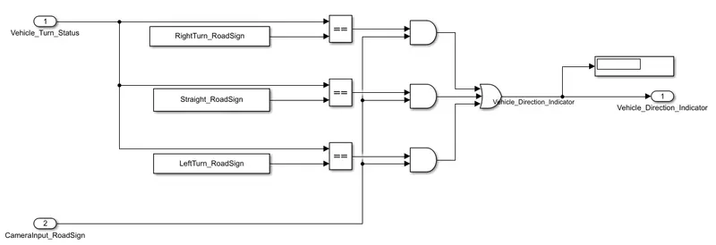
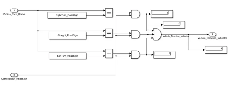
The input to this subsystem is Vehicle_Turn_Status signal from the requirement_1 and the CameraInput_RoadSign as the second the input. Initially the Vehicle_Turn_Status is compared with calibration values for raod signs using equal to relational operator block, output of the same is given as input to the AND operator and the other input to the AND operator is CameraInput_RoadSign.
The purpose of using AND operator is when both the Vehicle_Turn_Status and the CameraInput_RoadSign for the particular is turn is true, only then the output should be true. To get a single output, OR operator is used with three inputs. when either of the inputs are true, then the vehicle indicator will be ON.
Thus the Logic for both the requirements is created successfully.
Steps to create Simulink Data Dictionary (SLDD):
Modelling Tab ==> link to Data Dictionary and create the new SLDD.
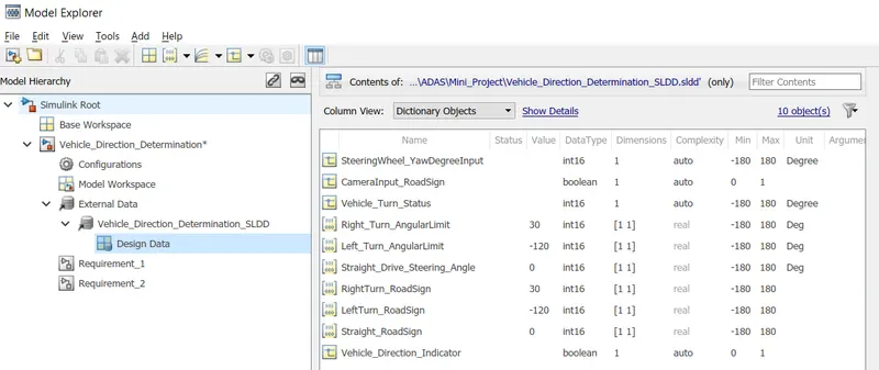
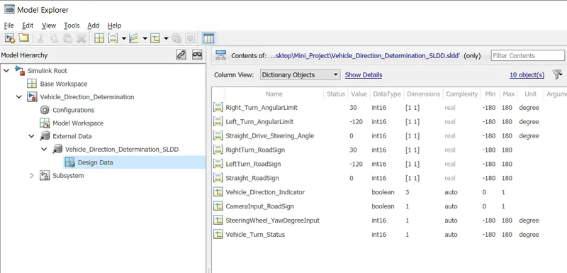
Add the Simulink signal with datatype, dimension, min, max and units for the input and output signals.
Add the Simulink parameter for the calibration values.
Storage class for Input signals: ImportedExtern; Storage class for Output signal: Export to File; Storage class for local signals: localizable; Storage class for calibration signals: Const.
Requirement Tagging & Traceability:
Copy the requirements to the word document and keep the word file open.
Select the requirement data which to be mapped with the respective subsystem. Right click on the Subsystem ==> link to selection in word.
Now you can find the requirement tagged with the subsystem.
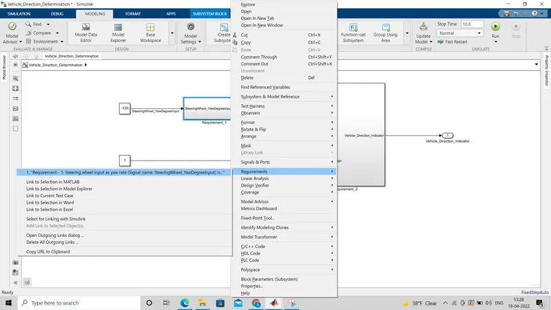
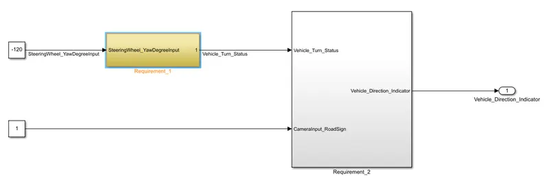
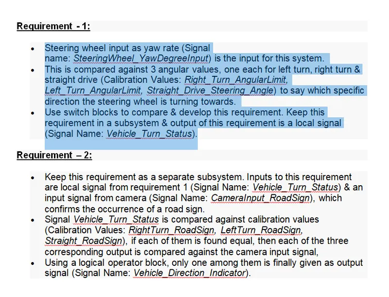
when you on the click on the tagged requirement, the respective subsystem will be highlighted as shown in the picture below. At the same time, the requirement in the word file will also be highlighted.
Model Advisor:
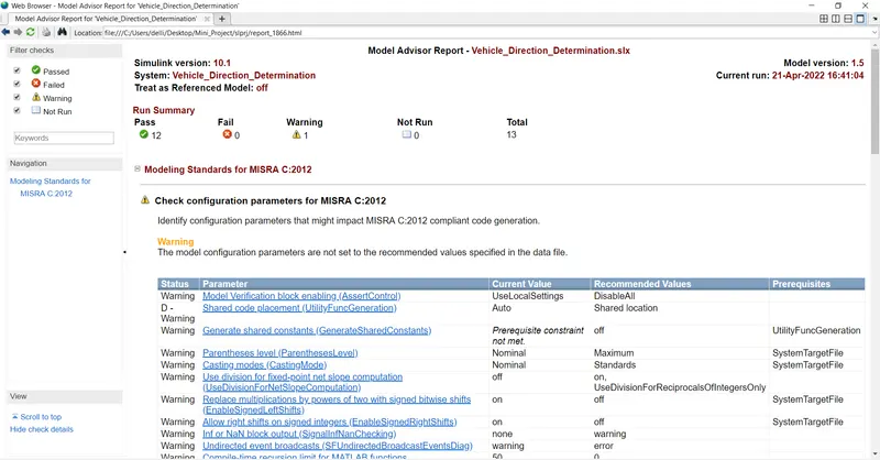
Model Advisory check is to verify whether our model is meeting the standards like MAAB, JMAAB , MISRA_C as mentioned by client.
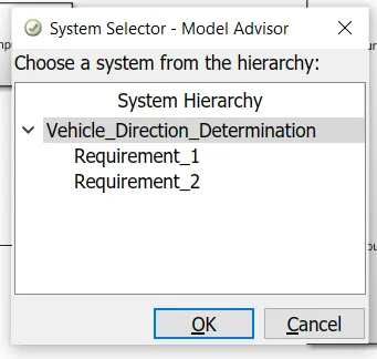
To run the model advisor, go to Apps ==> Model Advisor ==> Select either the whole model or the subsytem which you need to check.
Then select the standards and Run selected checks.
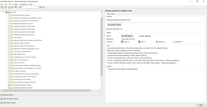
and the report can also be generated as the screenshot is attached below.
MIL & SIL Harness creation:
- To make the following changes in the configuration parameter setting
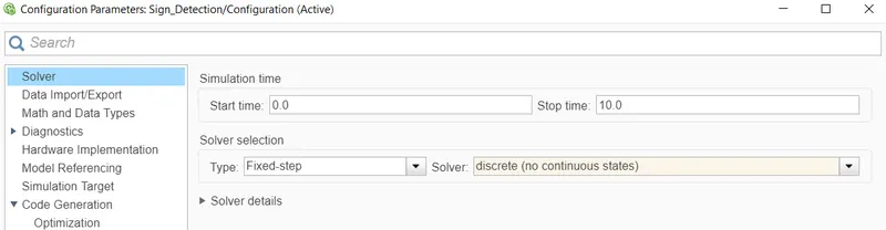
Solver settings
Solver type: Fixed step Solver : No continuous (discrete)
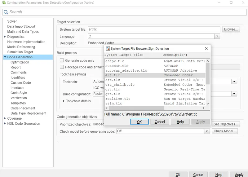
Code Generation
System target file : ert.tlc (embedded coder)
- Create a subsystem by including all logic in the model
- Create a new Simulink Data Dictionary (SLDD) using 'link to data dictionary' option in the Modelling tab.
- Create test harness
Right click on the subsystem and go for test harness ==> create for subsystem.
Choose the input and in advance settings verification mode as Normal for MIL testing and Software In loop for SIL testing.
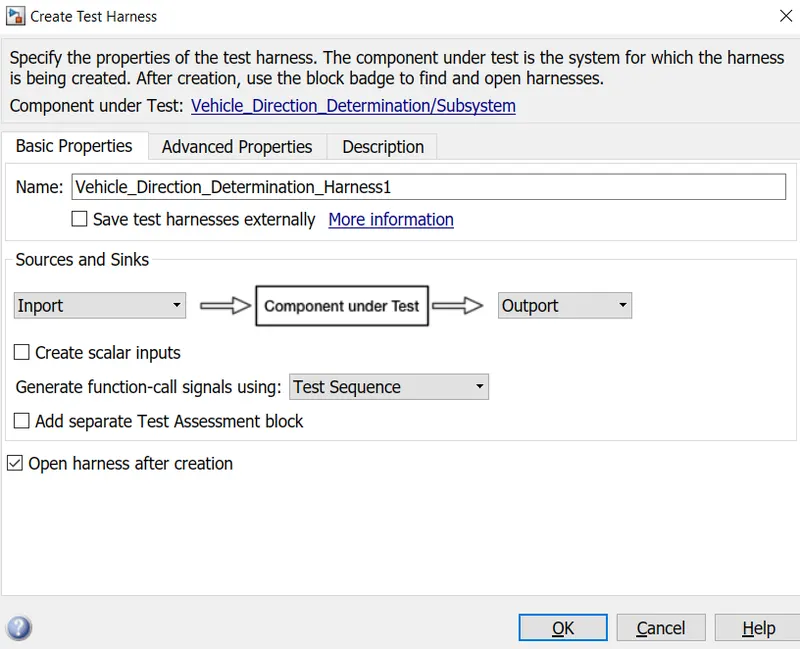
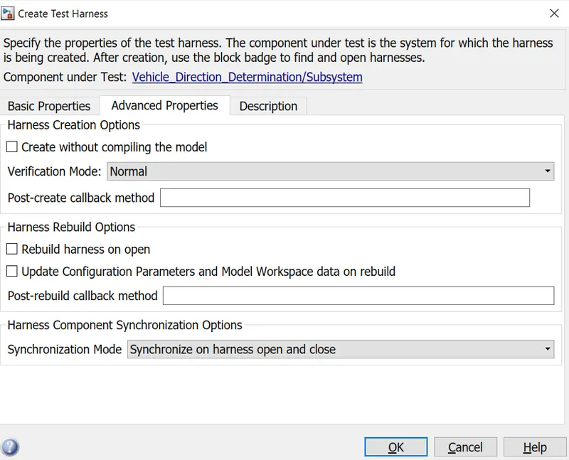
Now the harness environment for MIL testing is created screenshot of the same is attached below.
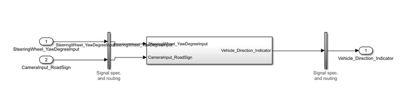
For SIL environment,
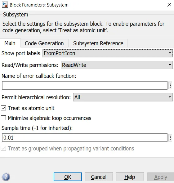
- Make the subsystem as Atomic Subsystem
Right click on the subsystem ==> block properties ==> check treat as atomic unit and give the model sample time.
- Create test harness
Right click on the subsystem and go for test harness ==> create for subsystem.
Choose the input and in advance settings verification mode as Normal for MIL testing and Software In loop for SIL testing.
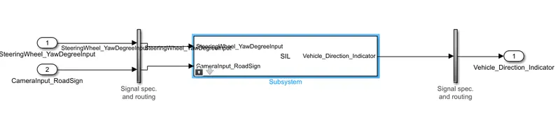
Now the harness environment for SIL testing with S_Function block is created screenshot of the same is attached below.
Code Generation:
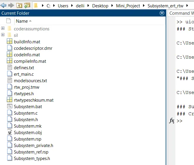
While creating the harness for the SIL testing, C_code has been generated. A new folder called Subsystem_ert_rtw is created in the current directory which contains all the generated C-code files.
Another way to generate code without creating the harness is
- First do the confiduration parameter settings.
- Go to Apps ==> Embedded coder ==> C/C++ tab will created then click on build to generate the code.
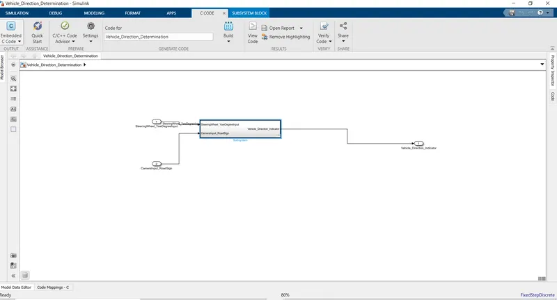
Thus the MIL & SIl testing harness and the code generation has done successfully.
Results and discussion:
Lets give the input to the model using constant blocks
SteeringWheel_Yawdegree_Input as 30 deg
Camera_Road_Sign as 1
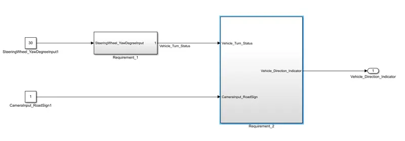
The output from the requirement_1 subsystem will be Right_Turn_Angular_Limit ie) 30 deg.
Then the output from the Requirement_2 subsytem is 1 since the Right_Turn is High while passing the OR gate to get a single output Vehicle_Turn_Indicator. The output here will be always true unless otherwise Camera_RoadSign_input is 0(low).
As the input given is 30deg which indicates the right_turn, we can see the output is also indicating the same. Thus the model satisfies the given requirements.