Project 1 (Mini Project on Vehicle Direction Detection
bjective of Mini Project:
- Development of MATLAB Simulink model as per requirement.
- Tag the requirements to the simulink model; tagging requirement 1 & requirement 2 to their corresponding subsystems is fine.
- MBD compliant changes, Data Dictionary creation & code generation is added advantage, and that is not scope of this project.
- If choosing code generation, Storage class for Input signals: ImportedExtern; Storage class for Output signal: Export to File; Storage class for local signals: localizable; Storage class for calibration signals: Const.
- Choose sample time for all signals as 0.01s
TASK:
- Steering wheel input as yaw rate (Signal name: SteeringWheel_YawDegreeInput) is the input for this system. and input signal from camera (Signal Name: CameraInput_RoadSign), which confirms the occurrence of a road sign.
- camera reads the road signs & stores into its memory with unique values for left turn, right turn & straight drive. Depending on the direction it is taking, final indication is given to the driver – as an indication if he is driving in the recommended direction or not.
- THE o/p of the system is boolean value which specify the vehicle is turning right,left or straight.
DEVELOPMENT OF SIMULINK MODEL:
the main subsystem vehicle_direction along with i/ps (Signal name: SteeringWheel_YawDegreeInput) and (Signal Name: CameraInput_RoadSign) and o/p signal is vehicle_direction_indicator shown in below.
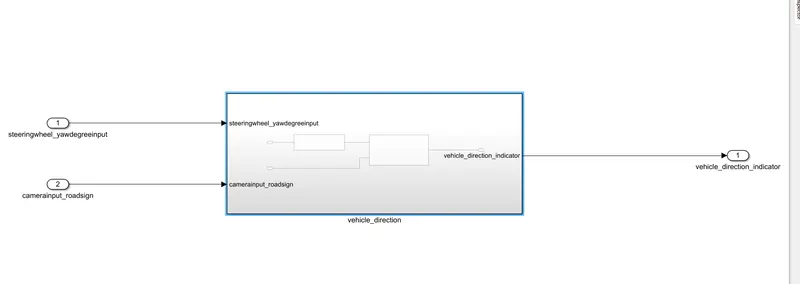
the main subsystem vehicle_direction is further divided into two more subsystem one is requirement 1 and second one is requirement 2
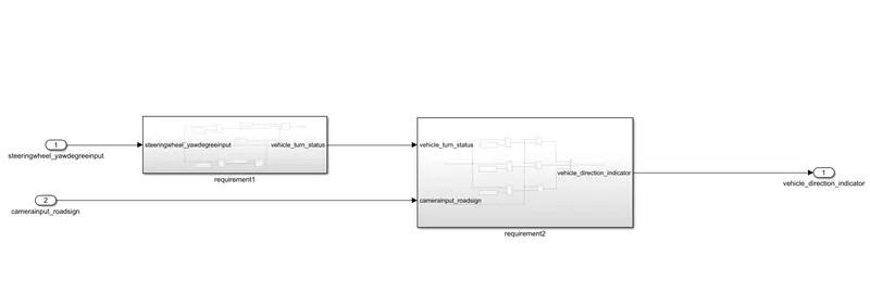
REQUIREMENT 1:
- Steering wheel input as yaw rate (Signal name: SteeringWheel_YawDegreeInput) is the input for this system.
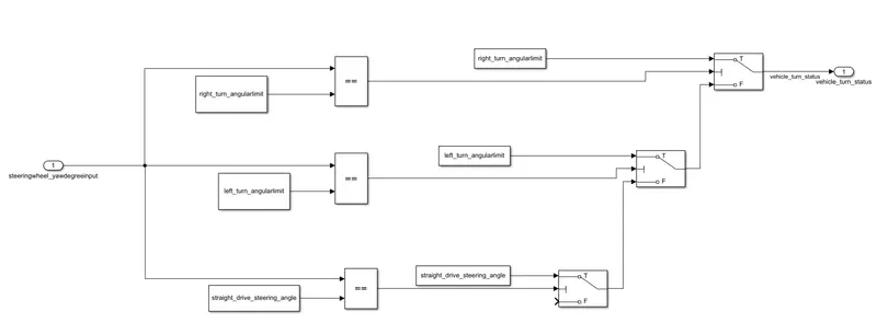
- This is compared against 3 angular values, one each for left turn, right turn & straight drive (Calibration Values: Right_Turn_AngularLimit, Left_Turn_AngularLimit, Straight_Drive_Steering_Angle) to say which specific direction the steering wheel is turning towards.
- Use switch blocks to compare & develop this requirement. Keep this requirement in a subsystem & output of this requirement is a local signal (Signal Name: Vehicle_Turn_Status).
the i/p signal SteeringWheel_YawDegreeInput is compared with This is compared against 3 angular values, one each for left turn, right turn & straight drive with relational operator==.(Calibration Values: Right_Turn_AngularLimit, Left_Turn_AngularLimit, Straight_Drive_Steering_Angle).to say specific direction the steering wheel is turning towards.
the three switch block are used to implement the if-else logic.the output operator is given as a condition input to each block.
REQUIREMENT2:
- Keep this requirement as a separate subsystem. Inputs to this requirement are local signal from requirement 1 (Signal Name: Vehicle_Turn_Status) & an input signal from camera (Signal Name: CameraInput_RoadSign), which confirms the occurrence of a road sign.
- Signal Vehicle_Turn_Status is compared against calibration values (Calibration Values: RightTurn_RoadSign, LeftTurn_RoadSign, Straight_RoadSign), if each of them is found equal, then each of the three corresponding output is compared against the camera input signal,
- Using a logical operator block, only one among them is finally given as output signal (Signal Name: Vehicle_Direction_Indicator).
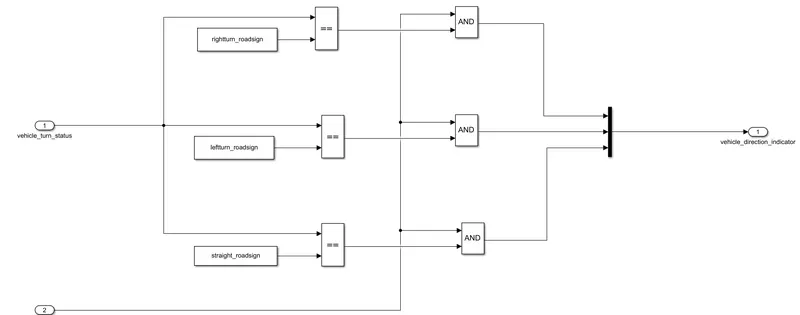
HERE the Vehicle_Turn_Status is compared against calibration values (Calibration Values: RightTurn_RoadSign, LeftTurn_RoadSign, Straight_RoadSign), if each of them is found equal, then each of the three corresponding output is compared against the camera input signal.
here == used to compare Vehicle_Turn_Status is compared against calibration values.if those equal the signal goes to AND block the and block compares the : CameraInput_RoadSign if both signals are 1 the o/p shows the Vehicle_Direction_Indicator.
CREATION OF SLDD
1.first open untitled document here you find modeling block .
2.when we clink on the modeling block we get model setting , when clicking on the model setting we get model properties
3.when we click on model properties we the below popup window
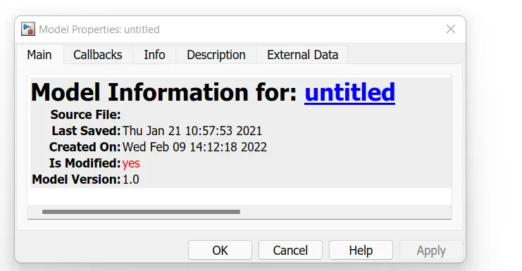
then click on to external data we find like below window
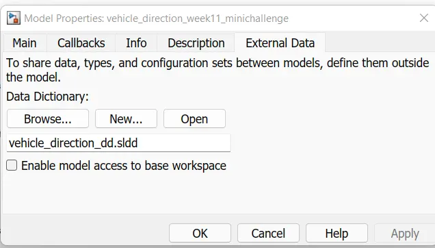
then click on ok we get popup window like below
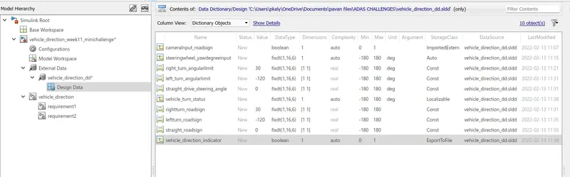
the showing above like that we create signals and constant from the requirement of problems.
TAGGING OF SIMULINK MODEL:
the steps involved in the tagging a requirement in the simulink model is to first highlight the requirement statement in the word document ,then the right click on the subsystem in the model that has to tagged ,then requirements and then link to selection in word.
Requirement - 1:
- Steering wheel input as yaw rate (Signal name: SteeringWheel_YawDegreeInput) is the input for this system.
- This is compared against 3 angular values, one each for left turn, right turn & straight drive (Calibration Values: Right_Turn_AngularLimit, Left_Turn_AngularLimit, Straight_Drive_Steering_Angle) to say which specific direction the steering wheel is turning towards.
- Use switch blocks to compare & develop this requirement. Keep this requirement in a subsystem & output of this requirement is a local signal (Signal Name: Vehicle_Turn_Status).
Requirement – 2:
- Keep this requirement as a separate subsystem. Inputs to this requirement are local signal from requirement 1 (Signal Name: Vehicle_Turn_Status) & an input signal from camera (Signal Name: CameraInput_RoadSign), which confirms the occurrence of a road sign.
- Signal Vehicle_Turn_Status is compared against calibration values (Calibration Values: RightTurn_RoadSign, LeftTurn_RoadSign, Straight_RoadSign), if each of them is found equal, then each of the three corresponding output is compared against the camera input signal,
- Using a logical operator block, only one among them is finally given as output signal (Signal Name: Vehicle_Direction_Indicator).
MODEL ADVISER:
for we goto modeling option in that we can find model advisor block and clicking the we select hole system we can we can find a window like below
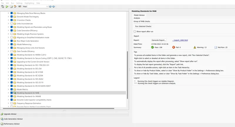
in that we can find that your model is under the guidelines of MAB