Vehicle Direction Detection ADAS Project
General Overview:
Identifying the direction of the vehicle is one of the important & diverse features in Autonomous driving & Advanced Driver Assistance Features. This particular sub-feature of identifying the direction of vehicle is basically identifying the direction the vehicle is taking based on the camera input.
Camera reads the road signs & stores into its memory with unique values for left turn, right turn & straight drive. Depending on the direction it is taking, final indication is given to the driver – as an indication if he is driving in the recommended direction or not.
Vehicle Direction Determination can also be coupled along - side features like GPS systems to identify whether the vehicle is reaching its destination in an optimized manner. This sub feature can also be used along with Lane Detection, Highway Warning, Ramp Entry / Exit in Wrong Way Detection etc.
Objective:
- Development of MATLAB Simulink model as per requirement.
- Tag the requirements to the simulink model; tagging requirement 1 & requirement 2 to their corresponding subsystems is fine.
- MBD compliant changes, Data Dictionary creation & code generation is added advantage, and that is not scope of this project.
- If choosing code generation, Storage class for Input signals: ImportedExtern; Storage class for Output signal: Export to File; Storage class for local signals: localizable; Storage class for calibration signals: Const.
- Choose sample time for all signals as 0.01s.
Advanced Driver Assisstance System(ADAS):
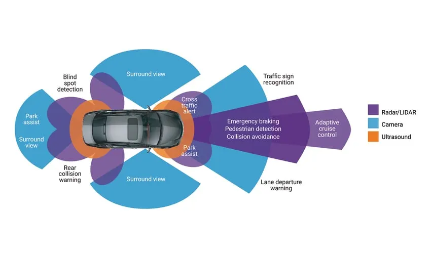
Almost all vehicle accidents are caused by human error, which can be avoided with Advanced Driver Assistance Systems (ADAS). The role of ADAS is to prevent deaths and injuries by reducing the number of car accidents and the serious impact of those that cannot be avoided.
Essential safety-critical ADAS applications include:
- Pedestrian detection/avoidance
- Lane departure warning/correction
- Traffic sign recognition
- Automatic emergency braking
- Blind spot detection
- Vehicle Direction Detection
These lifesaving systems are key to ensuring the success of ADAS applications, incorporating the latest interface standards and running multiple vision-based algorithms to support real-time multimedia, vision co-processing, and sensor fusion subsystems.
Self-driving cars use a variety of these applications and technologies to gain 360-degree vision, both near (in the vehicle’s immediate vicinity) and far. That means hardware designs are using more advanced process nodes to meet ever-higher performance targets while simultaneously reducing demands on power and footprint.
Requirement - 1:
- Steering wheel input as yaw rate (Signal name: SteeringWheel_YawDegreeInput) is the input for this system.
- This is compared against 3 angular values, one each for left turn, right turn & straight drive (Calibration Values: Right_Turn_AngularLimit, Left_Turn_AngularLimit, Straight_Drive_Steering_Angle) to say which specific direction the steering wheel is turning towards.
- Use switch blocks to compare & develop this requirement. Keep this requirement in a subsystem & output of this requirement is a local signal (Signal Name: Vehicle_Turn_Status).
Requirement – 2:
- Keep this requirement as a separate subsystem. Inputs to this requirement are local signal from requirement 1 (Signal Name: Vehicle_Turn_Status) & an input signal from camera (Signal Name: CameraInput_RoadSign), which confirms the occurrence of a road sign.
- Signal Vehicle_Turn_Status is compared against calibration values (Calibration Values: RightTurn_RoadSign, LeftTurn_RoadSign, Straight_RoadSign), if each of them is found equal, then each of the three corresponding output is compared against the camera input signal,
- Using a logical operator block, only one among them is finally given as output signal (Signal Name: Vehicle_Direction_Indicator).
Signals & Calibration Data List:
|
Signal / Calibration Name |
Signal Type |
Data Type |
Dimension |
Min |
Max |
Initial Value |
Units |
|
SteeringWheel_YawDegreeInput |
Input |
Int16 |
1 |
-180 |
180 |
- |
Deg |
|
CameraInput_RoadSign |
Input |
Boolean |
1 |
0 |
1 |
- |
- |
|
Vehicle_Turn_Status |
Local |
Int16 |
1 |
-180 |
180 |
- |
Deg |
|
Right_Turn_AngularLimit |
Calibration |
Int16 |
[1 1] |
-180 |
180 |
30 |
Deg |
|
Left_Turn_AngularLimit |
Calibration |
Int16 |
[1 1] |
-180 |
180 |
-120 |
Deg |
|
Straight_Drive_Steering_Angle |
Calibration |
Int16 |
[1 1] |
-180 |
180 |
0 |
Deg |
|
RightTurn_RoadSign |
Calibration |
Int16 |
[1 1] |
-180 |
180 |
30 |
Deg |
|
LeftTurn_RoadSign |
Calibration |
Int16 |
[1 1] |
-180 |
180 |
-120 |
Deg |
|
Straight_RoadSign |
Calibration |
Int16 |
[1 1] |
-180 |
180 |
0 |
Deg |
|
Vehicle_Direction_Indicator |
Output |
Boolean |
1 |
0 |
1 |
- |
- |
Building the MATLAB model:
Step 1: Creating the main subsystem with all the inputs and output signal.
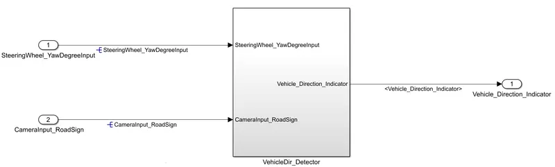
Here SteeringWheel_YawDegreeInput and CameraInput_RoadSign are the input signals to the system and Vehicle_Direction_Indicator is the output to the subsystem.
Step 2: Creating the subsystems inside the primary subssystems according to the requirements given.

In this arrangement, two subsystems are created according to the two requirements given. The output of the Req_1 becomes the input to the Req_2 subsystem. The input signal SteeringWheel_YawDegreeInput is given to the Req_1 subsystem whereas the input signal CameraInput_RoadSign is given to the Req_2 subsytem. The output of the overall arrangement is the primary output signal Vehicle_Direction_Indicator.
Step 3: Building the logic of Requirement 1.
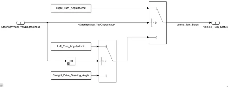
Here the input signal SteeringWheel_YawDegreeInput is compared against two switch blocks in which the 1st switch block pass the input if the its value is greater tha zero. In the 2nd switch the input is compared for negative and zero value. If the value of the input is negative the Left_Turn_AngularLimit value will be passed and if the value of the input is zero the Straight_Drive_Steering_Angle value will be passed as the output. The output of this subsystem is Vehicle_Turn_Status.
Step 4: Building the logic of the Requirement 2.
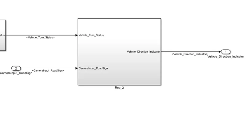
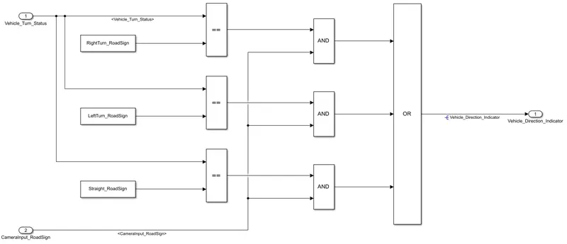
In this arrangement the local signal Vehicle_Turn_Status is comapred against three calibration values namely RightTurn_RoadSign, LeftTurn_RoadSign and Straight_RoadSign using the relational operator. The ouput of these relational operator block is again compared against the second input signal CameraInput_RoadSign using the AND gate block. In this case only one of the output is 1 and the rest is 0. These signals are passed through the OR gate which gives our final output Vehicle_Direction_Indicator as a boolean signal.
Step 5: Creating the Simulink Data Dictionary.
Step 6: Generate the Model Advisor report.
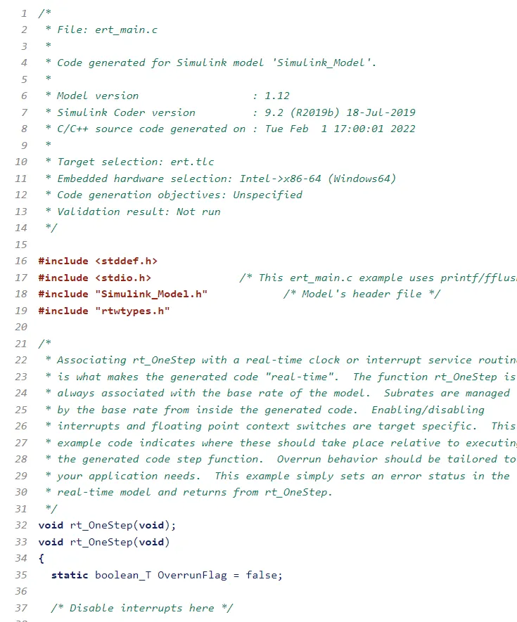
Step 7: Generate the C code for the final delievery.
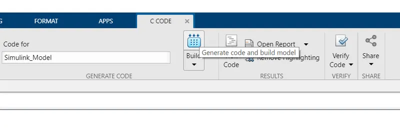
Click on the build button to generate the c code.
Conclusion:
- The MBD model for Vehicle Direction Detector is build successfully.
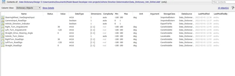
- The Simulink data dictionary is created with all the neccessary signals and calibration values.
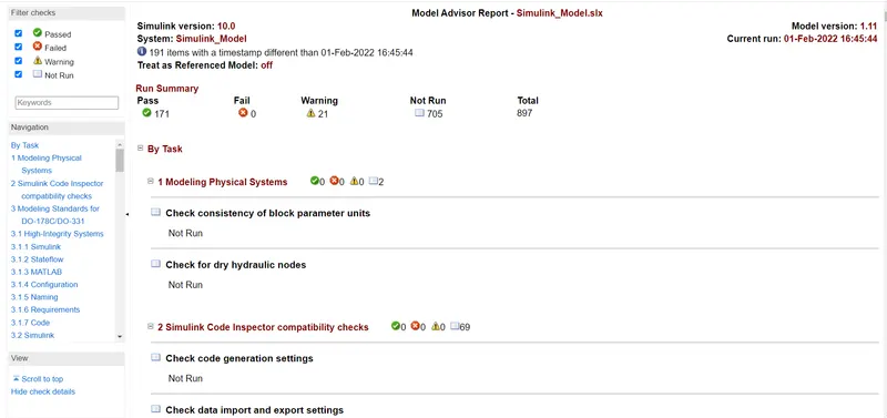
- Model advisor report is gnerated successfully with no errors.
- The code generation is done.