Project 1-Meshing of Rear Wheel Holder challenge
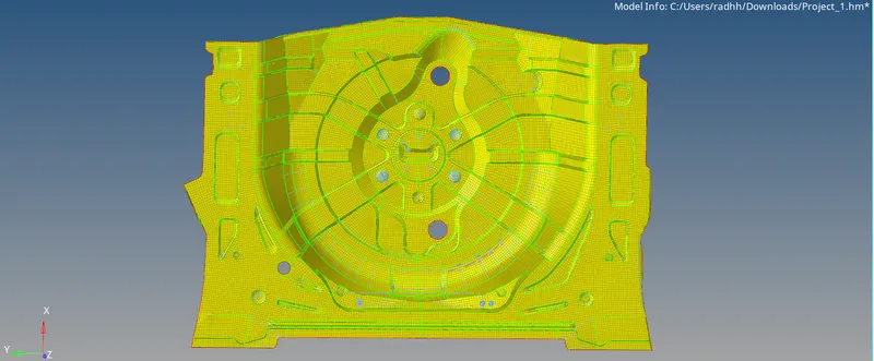 Project 1-Meshing of Rear Wheel Holder challenge
Aim -
- To perform preprocessing on the given Rear Wheel Holder Sheet Metal component using hypermesh preprocessing software.
Objective -
- To generate the mid surface manually and do a geometry clean up on the component.
- To generate a mesh and to get a proper mesh flow on the given component with low tria concentration.
- To check the elements quality according to the given quality criteria.
- To assign a thickness for the component.
Procedure -
Phase 1-Importing
- Hence we are importing a given CAD geometry into hypermesh.
- There are file formates like IGES and STEP where we can import these file formats into any CAD,CAE Softwares.
- But in hypermesh we can only import three file formates like
- IGES [Initial Graphics Exchange Specification].
- STEP [Standard for the Exchange of Product Model Data].
- Solidworks.
- IGES,STEP,These two are standard file formats which are used most in industries.
- While importing the file into the graphical user interface,Be sure whether the file is .step or .iges file.
- File > Import > Import Model > File type > Open File > Import File.
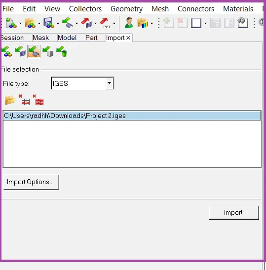
Figure 1-Importing Model into GUI.
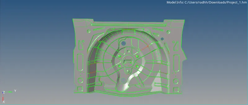
Figure 2-Imported Model into GUI.
- Switch to the topo mode and examine whether the solid exsist in the component or not,If solids exsist,Delete the solids cause we are doing 2d meshing on the component.
- You can find topo mode in the tool bar panel.
- Delete [F2] >> Solids >> Select by box selection >> Delete Entity.
- If solids exsist,It will be highlighted in the green colour.
Phase 2- Examining
- Before working on the model.We have to check the geometry if there are any errors like
- Damaged Geometry.
- Free edges in unnecessary areas.
- Unnecessary points on the lines.
- Unnecessary Connections and connectivity error.
- There are some free edges in the model,So clear that free edges in the parent component,Then only you can extract mid surface properly without any glitches in the mid surface geometry.
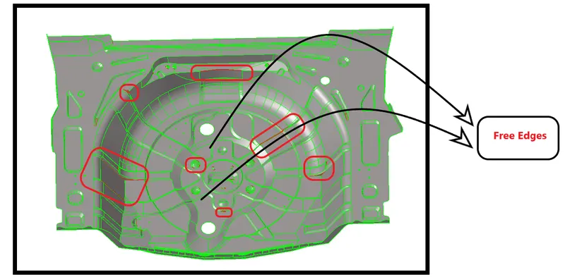
Figure 3-Free edges in the parent component
2:1 Inspecting
- While inspecting the model,It is a spare wheel floor panel which is used to keep the spare wheel in the car.
- While observing the model,There are 17 [Seventeen] components in the model.
- Organize them to a single component or delete the unnecessary components.
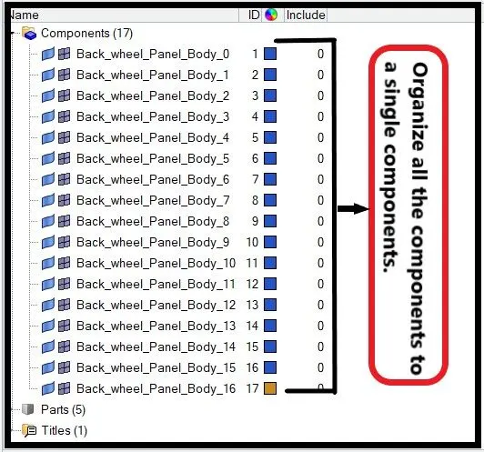
Figure 4-Unnecessary Components.
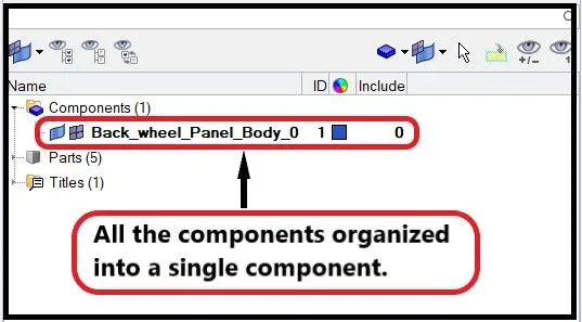
Figure 5-All the components organized into one
2:2 Organizing
- We use organize tool to (re)organize your database by copying or moving data (entities) among collectors, includes, or parts.
- Select an entity type to copy/move, then use the selector to select specific entities to copy/move. The current collector serves as the default destination.
- Elements can be copied/moved into component collectors or groups.Lines, surfaces, solids, points, and connectors can be copied/moved into component collectors.
- Here we are selecting the collectors and we are organizing it to one collector.
- Tool >> Organize >> Collector SubPanel >> Switch to Surfaces >> Select by Collector >> Move.

Figure 6-Organize Panel

Figure 7-Switch to the surfaces and select by collector

Figure 8-Check the components to organize
2:3 Check for the Thickness
- Now go and measure the distance in every region.
- We are ensuring whether some regions of this component having uniform thickness or not.
- The component given to us is sheet metal component.
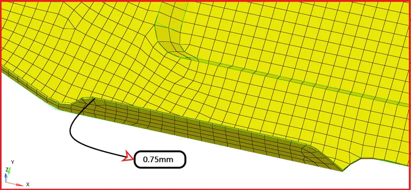
- The thickness of this stepney floor panel is 0.75 mm.
- You can measure the thickness by two methods.
i) Geometry > Dimensioning > Select the Point1 and Point2.

Figure 9-Dimensioning Panel
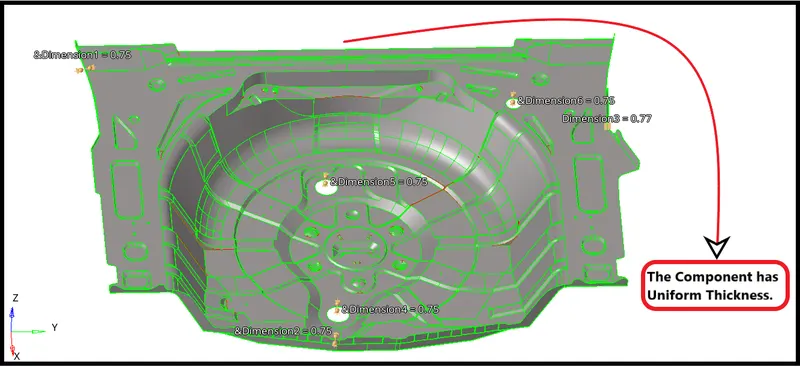
Figure 10-The Component has Uniform Thickness
ii) Tool [F4] > Distance > Points > Select the Point1 and Point2.

Figure 11-Distance Panel
2:4 Check for Symmetry
- This tool is to find symmetrical surfaces or compare selected surface sets for symmetry. You can reorganize found symmetric surfaces into separate components or delete one subset of a pair of symmetric surface sets.
- This can be helpful with highly symmetrical components, because you can then perform geometry cleanup on only one half, mesh it, and then mirror the mesh instead of having to clean up the entire component prior to meshing.
- Geom >> Surface Edit [Shift + F9] >> Symmetry >> Axis >> Base Point.
- Find symmetry-Locate surfaces within a single component that are mirror images of one another across a plane of symmetry that you specify.
- Delete Positive-Delete the symmetric surfaces on the positive side of the symmetry axis. Used when finding symmetry.
- Delete Negative-Delete the symmetric surfaces on the negative side of the symmetry axis. Used when finding symmetry.

Figure 12-Symmetry Sub Panel
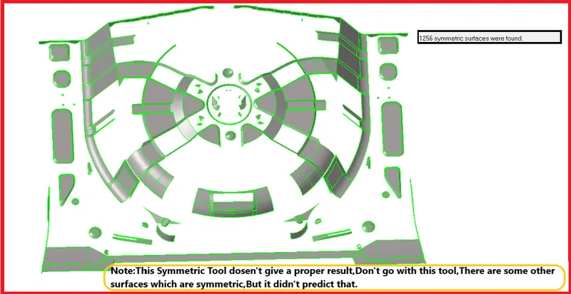
Figure 13-Surfaces which are symmetric
Phase 3 - Geometric Clean Up on the Parent Component
- If we want we can do geometry clean up on the parent component or after extracting the midsurface also, we can do geometry clean up on mid surface.
3:1 Check for Geometric Deformations
- We should also check for any geometric deformations like
- Damaged Geometry in some regions.
- Overlapped Surfaces.
- Free edges.
- Unnecessary Connections (Extra points and lines).
- Connectivity error.

Figure 14-Damaged Surfaces
- Here i'm doing geometric clean up on the parent component,There is no need to work on parent geometry,If you want you can work on parent geometry or it's fine.
- Now fix this damaged surface by deleting the surface.
- Geometry >> Quick edit [F11] >> Delete Surface >> Surface (Select).

Figure 15-Quick Edit Panel
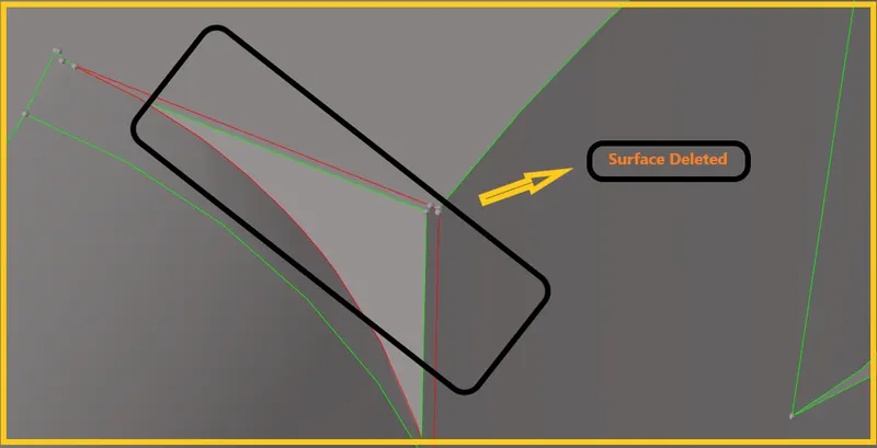
Figure 16-Surface has been deleted
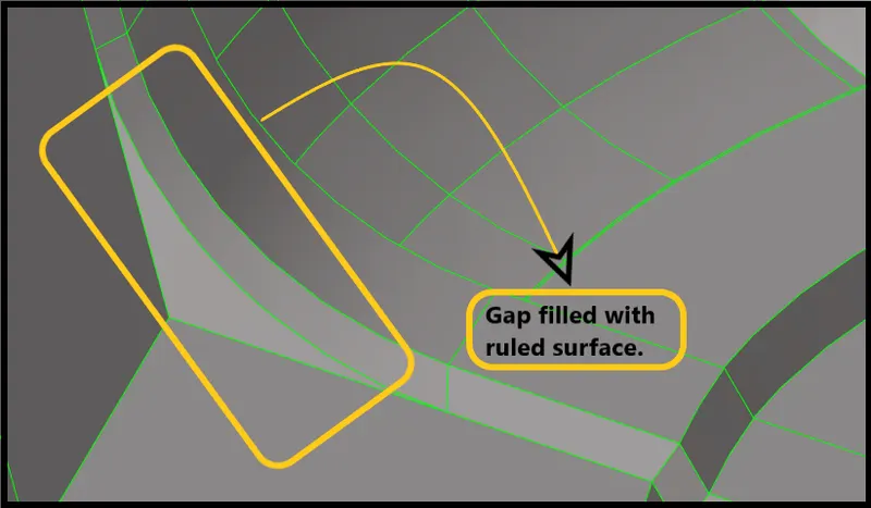
- Now fill this gap with ruled surface,
- Use the first selector to define the first edge of the surface to create. Use the second selector to define the second edge of the surface to create.

Figure 17-Ruled Surface Sub-Panel
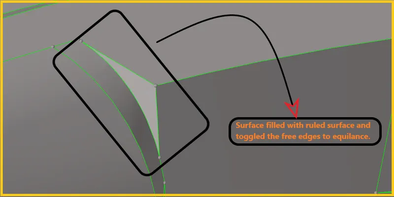
Figure 18-Gap Filled with Ruled Surface
3:2 Fixing Damaged Geometry in surfaces.
- Deformed surfaces occur due to the following reasons like
- Overlapping surfaces
- Connectivity issues
- Sometimes this issue occurs due to replacing the points multiple times
- These issues can be rectified by using the tools called
- We can fix the geometry by quick edit tools.
- There some sub tools in the quick edit panel,I have described every tool below,Have a look.
i) Geometry >> Quickedit >> split surface node.
- Select two locations of the nodes to split the surface and then select an additional node to continue to split the surface.
ii) Geometry >> Quickedit >> Split surf-line
- In this,select a node and select a line to split the surface,here the split will be perpendicular to the line chosen.
iii) Geometry >> Quick edit >> Adjust/set density.
- After meshing a particular surface.We can adjust the mesh density by using this tool.While meshing we will increase the
nodes to get a proper mesh flow.We can also increase nodes after meshing by using this tool.
iv) Geometry >> Quick edit >> Release points.
- Drag and select the surface,where you want release the points.After releasing the points.The free edges will exsists.
v) Geometry >> Quick edit >> Replace points.
- Move points from their current locations to the locations of other points,where we want them to replace it.
vi) Geometry >> Quick edit >> Add/Remove points.
- Use window selection (with the left mouse button and right mouse button ) to add and remove any points within the
selection box.
vii) Geometry >> Quick edit >> Add points on line.
- Specify the number of points that we wish to add to that line, and then select the desired line in our model.
viii)Geometry >> Quick edit >> Delete surface.
- Select the surface which we need to eliminate and delete it.
3:3 Filling Gaps on the Parent Geometry
- As we are doing auto mid surface extraction for this component,So try to fill the gaps in the parent geometry.
- You can also extract auto mid surface without filling gaps.
- We have to close the gaps,where there are free edges in the geometry.
- It will be very difficult to find the small free edges.
- So go to the Visualization tab

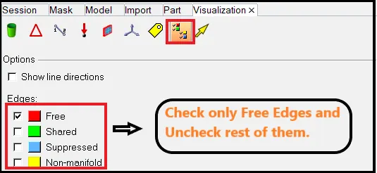
Figure 19-Visualization Tab
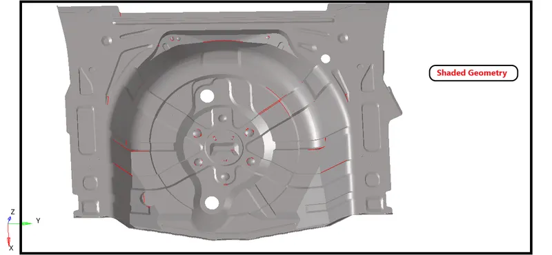
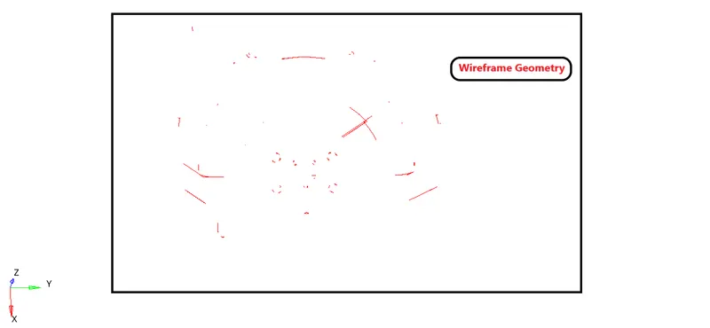
Figure 20-Free Edges on the Parent Geometry
- The gaps which are narrow,We can toggle them using Quick Edit Panel.
- Geom >> Quick Edit [F11] >> Toggle Edges >> Lines (Select).
Toggle Edge -
- Use the lines selector to select line(s).
- Left-click a free edge (red) to make it shared (green), or a shared edge to make it suppressed (blue).
- Right-click a suppressed edge to make it shared, or a shared edge to make it free.

Figure 21-Quick Edit Panel [Toggle Edge]
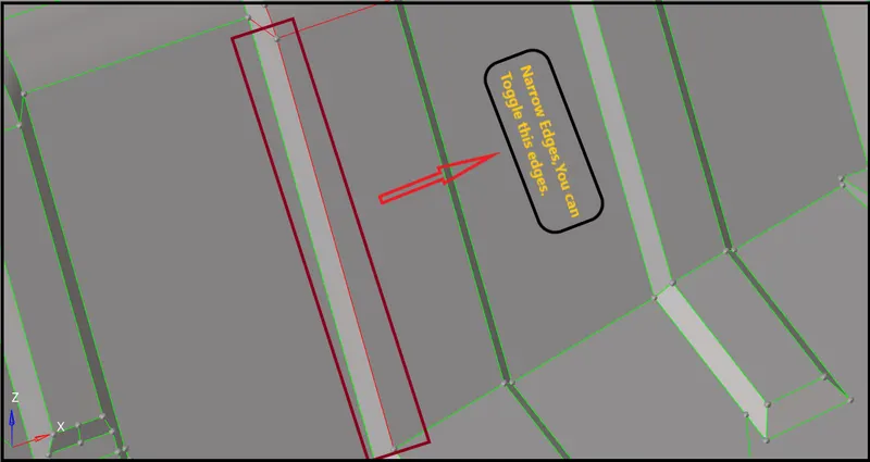
Figure 22-Narrow Edge
Filler Surface -
- This tool is used to fill the gaps which are bigger.
- Use the line(s) selector to select a closed-loop line (a hole) in your model to create a surface that fills the hole.

Figure 23-Quick Edit Panel [Filler Surface]
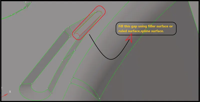
Figure 24-Bigger Gap
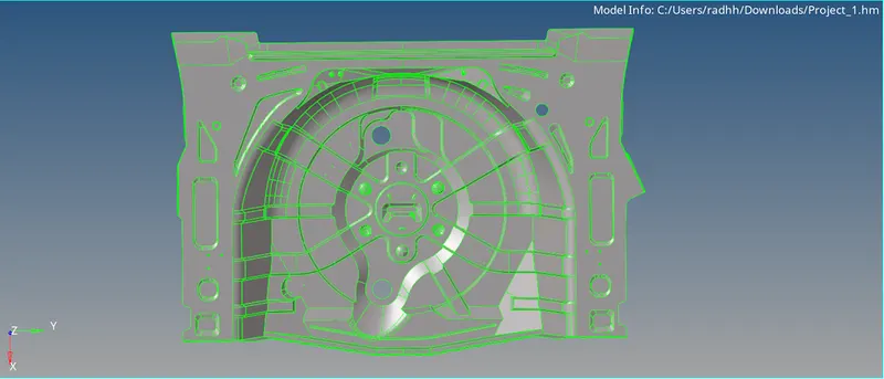
Figure 25-No Free Edges in the parent component
- Switch to tha visualization tab and uncheck all the boxes except free edge one and check whether the free edges exsist in the parent component or not.
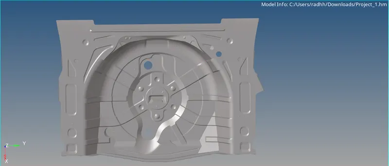
Figure 26-No free edges
Phase 4 - Extracting Mid Surface
- The midsurface has been extracted to the components which have less than 6mm thickness.
- We will be extracting midsurface for the sheetmetal and plastic components.
4:1 Why to Extract Mid Surface ?
- Before extracting the mid surface for every component,We should measure the thickness of the component and then we have to proceed to extract the mid surface.If the component thickness is less than 6mm then we will come to know it is a sheet metal component or plastic Component.
- For sheet metal and plastic components,Mid Surface extraction is must.
4:2 Midsurfacing: Process & Strategy-
1.Obtain a closed volume of surfaces or solids
- Midsurface : Auto midsurface requires an enclosed volume.
- Use topology repair techniques if needed.
2. For complex parts, try defeaturing the surface defining the volume
- This simplifies the part and may give better results with create solid.
3. Generate the midsurface using midsurface : auto midsurface
- Use surface pair for areas that need more control.
- Use midsurface : editing tools for midsurfaces that need fine tuning.
4. View the midsurface and correct errors using the midsurface editing functionalities
- Can generally use quick edit.
4:3 Extract the Mid Surface
- For this component,I'm using auto mid surface extraction.
- Auto Midsurface is used to to extract the midsurface of a more complicated group of surfaces that represent a solid part in one step.
- I'm extracting midsurface by Offset + Planes + Sweeps,Because this component has many features and sweeps.
- Offset + planes + sweeps-It is used to identify the places where a piece of plane or a piece of a sweep surface can be used as a middle surface. A middle surface is constructed at the remaining places in the model, for example the places where planar or sweep surface pieces cannot be used as a middle surface, by the same algorithm as in offset via the offset of the model's sides.
- Geom >> Mid surface >> Auto Midsurface >> Extraction process (Offset + Planes + Sweeps) >> Auto Extraction (Closed Volume) >> Surfaces (Displayed) >> Extract.

Figure 27-Mid Surface Panel

Figure 28-Extraction Options
- The mid surface created will be assigned to a new collector called Middle Surface.

Figure 29-Extracted Mid Surface
4:4 Check for the Duplicate Surfaces
- Sometimes,The duplicates surfaces may occur while extracting the mid surface.
- So check for the duplicates,Give a Clean UP Tolerance value as 0.1 and check.
- Geom >> defeature >> Duplicates >> Surfaces (Displayed) >> Cleanup Tol = 0.1 >> Find >> Delete.

Figure 30-Defeature Sub-Panel

Figure 31-No Duplicated Surfaces Were Found
Phase 5-Geometric Clean Up on the Mid Surface
- Do a geometric clean up on the mid surface extracted.
- Check for the free edges in the middle region of mid surface.
- If there are any free edges,Toggle them and eliminate that free edges.
5:1 Filling Gaps on the Surfaces which or not filled
- We need to fill the gaps (Free Edges) to get a connectivity while meshing.
- If we won't fill the gaps,There will be no connectivity while meshing.
- If we do analysis without filling that gaps,Forces won't be distributed in that regions,So fill the gaps and equivalence them.
- We can fill the surfaces by using following tools called
- Filler Surface
- Ruled Surface
- Spline
- Skin
i) Filler Surface -
- This tool is used to fill the gaps which are bigger.
- Use the line(s) selector to select a closed-loop line (a hole) in your model to create a surface that fills the hole.
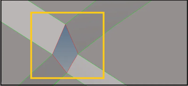
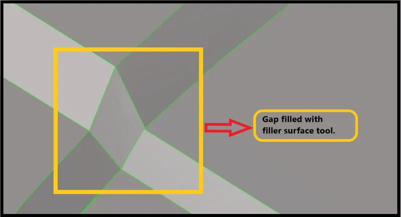
Figure 34-Gap filled with filler surface tool
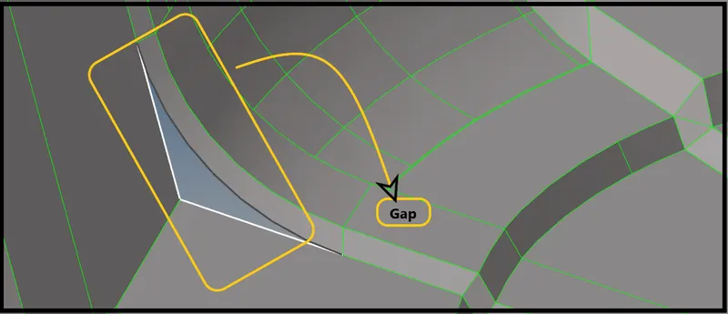
ii) Ruled Surface
- We can also fill the gaps using ruled surface.
- Ruled Surface is used to create surfaces by interpolating linearly between lines or nodes.
- Line List-Use the first selector to define the first edge of the surface to create. Use the second selector to define the second edge of the surface to create.
- If a node list is selected, a line will first be fit through the specified nodes.
- Go to Geometry >> Surfaces >> Ruled Surface >> Select Line List 1,2 >> Create.

iii) Spline
- We can use the Spline/Filler tool to create surfaces by filling in gaps, such as a hole in an existing surface.
- Select the lines, node list, or points that define the spline/filler area.
- Lines-Select two or more lines. The lines do not have to form a closed loop, as disconnected lines are first connected with straight lines. Both free lines and surface edges can be selected.
- Go to Geometry >> Surfaces >> Spline/Filler >> Select Lines.

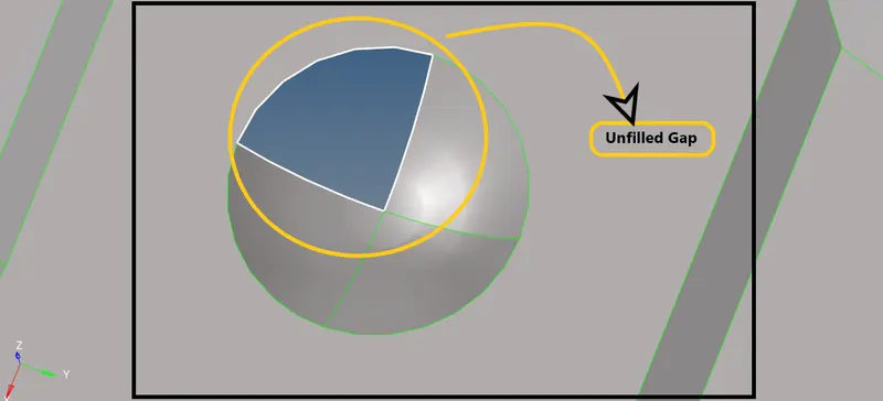
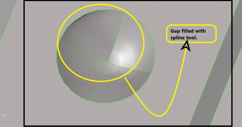
Figure 40-Gap Filled With Spline Tool
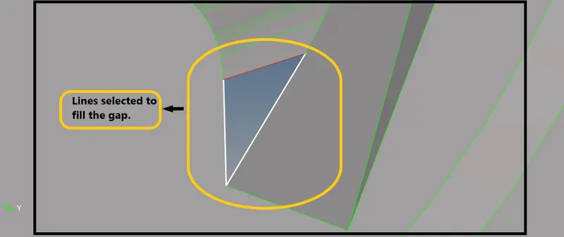
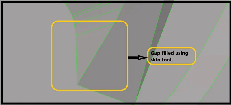
iv) Skin
- The skin tool is used to create a surface by skinning across lines.
- At least two input lines are required. Three or more input lines will fit a surface across all of the input lines, with the first and the last input lines defining the surface ends.
- Line List-Select the lines to use as input. The lines used to create the skin surface are automatically smoothed before the surface is created. As a result, the surface is created with a single face.
- Go to Geometry >> Surfaces >> Skin >> Line List >> Select Lines (Skinning across lines) >> Create.

5:2 Fixing Deformed Surfaces
- Due to complexity of the features,The software was unable to extract a good mid surface.
- There are some surfaces overlapping and there is no connectivity ,So fix this manually.Do a manual geometric clean up.
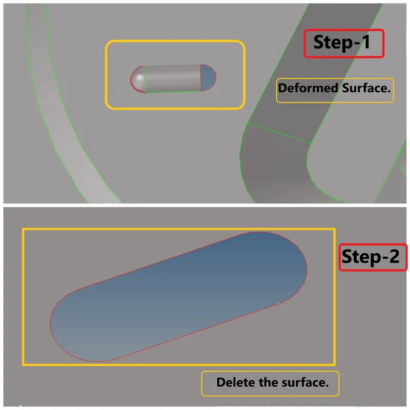
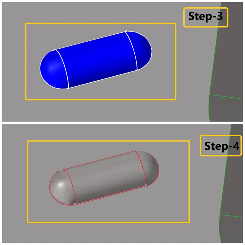
- Now switch on the parent component and take offset manually for the slot region.Select the surfaces and offset it.
- While making offsett,make the mid surface as current component and then offset.
- The manual offset can accessed by the surface edit panel.

- Before making offset check for the Vector normal.
- The arrows will be pointing towards the direction of the offset.
- If the arrow points are facing outward,give for reverse normal to make the arrows point inward.
- Vector Normal [If outward] >> Reverse Normal
- Another option to check for direction is to check for Color Normal:
- Blue indicates towards the screen or inward.
- Red indicates away from the screen or outward.
- If it shows Red, give for reverse normal and it should show blue.
- Color Normal [If Red] >> Reverse Normal
- Color Normal [If Blue] >> Offset
- Once everything is ok,Give offset.
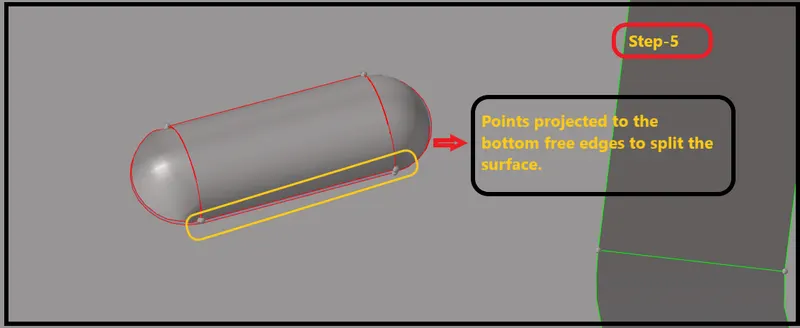
Figure 47-Points projected to the bottom free edge
- Here projected the points to the bottom free edge to split the surface.
- Go to Geometry >> Quick Edit [F11] >> Project Points >> Select Point >> Select line to project.
- Project Points is used to control to move free points to existing surfaces or lines. Choose whether this happens singly or as a chain of actions.
- Move the selected point(s) to the selected line.
- Perform additional projections by selecting a new set of points and a new line.

- Now replace the edges to get equivalence.
- Use Replace tool to replace.
Replace Tool -
- Go to Geometry >> Edge Edit >> Replace >> Select Moved Edge which we want to move >> Select Retaned Edge which we want to be reatined >> Clean Up tolerance as 1 or 2 >> Replace.
- It is used to move one edge line to the same edge as another, effectively combining the two edges into a shared edge at the location of one of the original edges.
- This functionality provides additional control over the toggle function. Individual selections are made for the line to move and the line to retain. The resulting shared edge will be at the location of the line selected as retained.
- The cleanup tolerance setting in this panel defines the maximum distance between the selected lines.
- Select the edge line to move the other lines to.

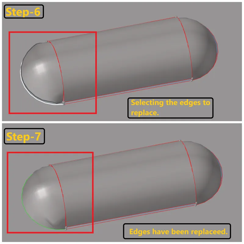
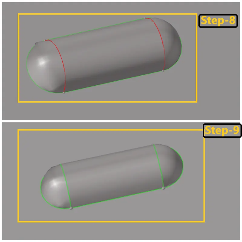
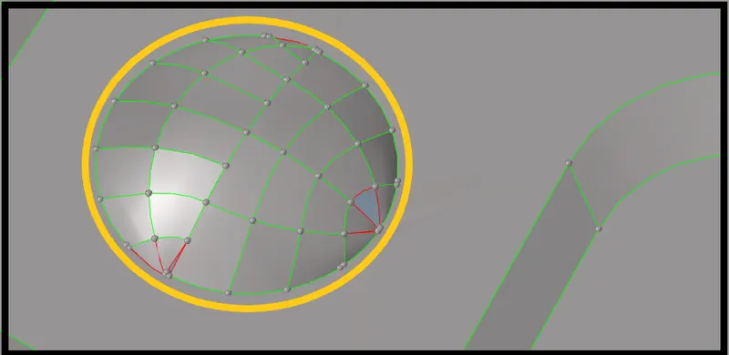
- Clear the free edges shown in the above fig 52,using filler surface,delete surface,toggling.
- Use these three tools to clear that free edges.
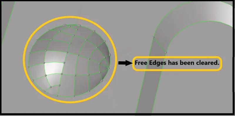
Figure 53-Free Edges have been Cleared
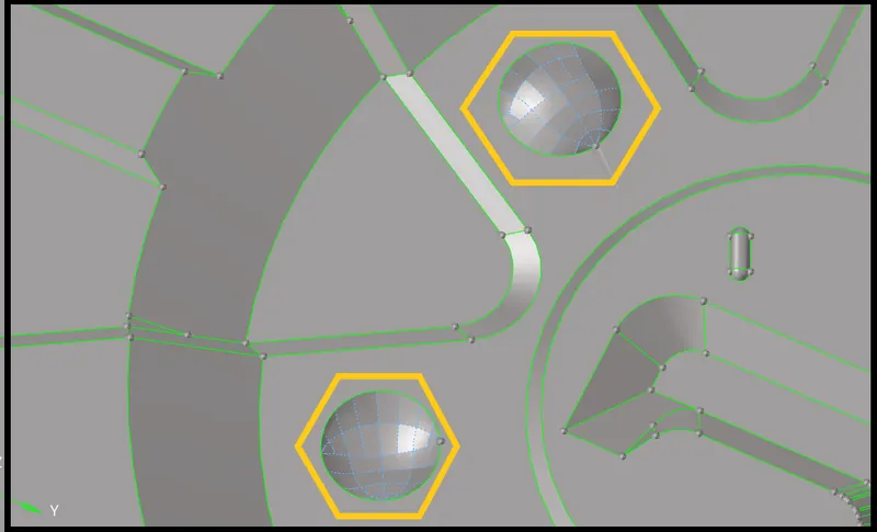
5:3 Delete Small Holes
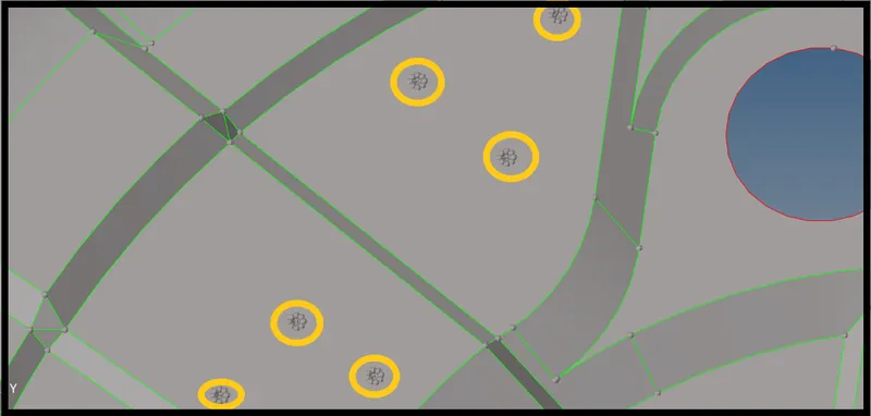
- Delete the small pin holes because we can't capture the feature there.
- So delete that samll pin holes,After deleting that fill that holes with the filler surface.
- Delete tool is used to delete data from a model database, preview and delete empty collectors, and preview and delete unused property collectors, material collectors, or curves.
- You can also delete an entire model database, if you wish to start with a clean database.
- Go to Tool >> Delete [F2] >> Surfaces >> Delete Entity.

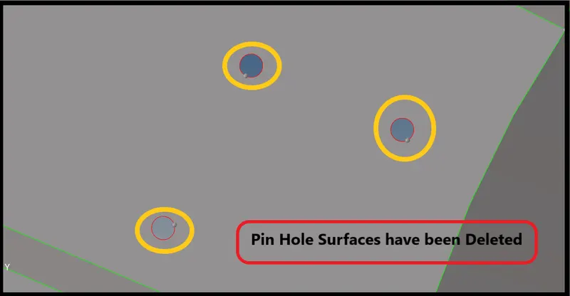
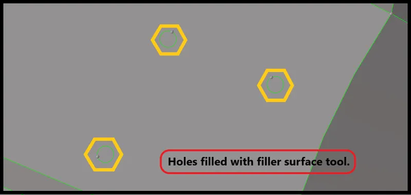
- Now fill that holes with filler surface tool from quick edit panel.
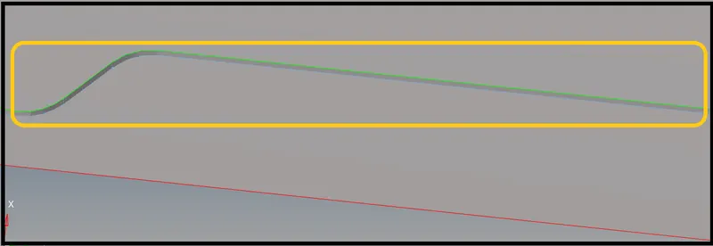
5:4 Toggle the edges which are failing for minimum length
- Toggle the edges which are failing for minimum length.
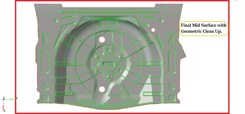
- Once geometry cleanup is completed (e.g. surfaces are stitched together — no unwanted free surface edges inside the geometry), meshing is next.
6:1 Enter the quality criteria what they given for the component
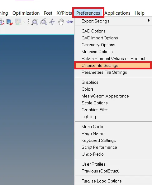
- Tool bar → preferences → criteria file settings → checks for the element criteria →Enter values → apply → ok.
- Before generating a mesh on the surfaces.Enter the quality criteria given tou us in the question.
- You can go and enter quality criteria in Tool bar → preferences → criteria file settings → checks for the element criteria →Enter values → apply → ok.
Target Element Size - 5 Units
| Sl. No. | Quality Criteria | Function / Definition | Value |
| 1 | Aspect Ratio Ratio | Ratio of Max. Length by Min. Length | 5 |
| 2 | Skewness | Deviation from the ideal shape | 45 |
| 3 | Warping | Angle between the 2 planes of the same element(Quad) | 15 |
| 4 | Taper | Convergence of a Quad element | 0.5 |
| 5 | Min. Length | Shortest length of any given element | 2 |
| 6 | Max. Length | Longest length of any given element | 8 |
| 7 | Min angle Quad | Minimum angle in any given Quad element | 45 |
| 8 | Max angle Quad | Maximum angle in any given Quad element | 135 |
| 9 | Min angle Tria | Minimum angle in any given Tria element | 20 |
| 10 | Max angle Tria | Maximum angle in any given Tria element | 120 |
| 11 | Tria % | Percentage of Tria on any meshed surface | 10 |
6:2 Conditions to be followed while meshing
- Feature Capturing
- Feature capturing is must while meshing.All the nodes must be connected to the shared edges.
- Tria Management
- Avoig higher number of trias.
- Important Parameter's in tria management
- No trias in corner's or edge's.
- No opposite trias.
- No back to back trias.
- No trias in fillets or hemmings(We can have minimum but anyhow try to avoid).
- No rotational quads.
- No trias should share a boundary with feature line.
- Connectivity between elements.
- Split and perform the mesh.
- Use mixed type mesh for irregular shaped surfaces and quads only for rectangular/square surfaces(Opposite sides should be parallel and equal).
6:3 Begin meshing the surfaces
- Start meshing from the centre regions or from least free edges.You will get proper mesh density and proper mesh flow.
How to Begin Mesh ?
- Start meshing form the least free edges,Like start meshing from the center.
- It will be easy to get proper mesh flow and we will get uniform mesh density.
- Don't mesh form the edges,It will be difficult and you will get many error,So start meshing from the center.
- Choose the element type while meshing.
- For this component we will be using mixed element type and working on it.
- We can also quads element type.This type can be used when we have rectangular surface.
- We can use Tria Element type.This type can be used for 3d tetra meshing.
Start Meshing
- Now start meshing on the surfaces,Go to 2D >> Automesh Panel >> Surfaces >> Element size = 5mm > Mesh Type : Mixed >> Check for align and size >> Mesh.
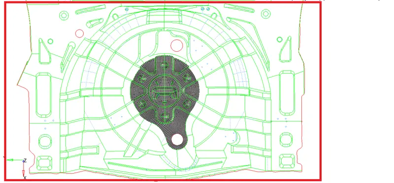
Figure 62-Meshing on Surface

Figure 63-Automesh Panel
- Select the appropriate mesh type based on the shape of the surface.
- Once we give for mesh, we can edit the mesh density by changing the number of nodes.
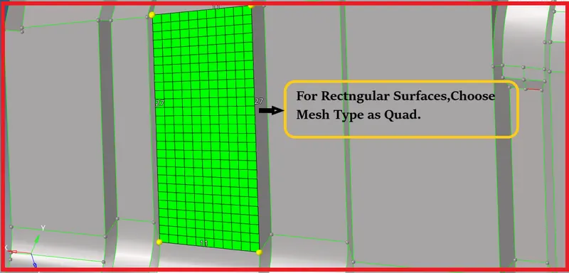
Figure 64-Mesh on the Rectangular Surface
6:4 Remesh and Rebuild Mesh
Remesh-
- Remesh is used to generate a mesh of plate elements using surface geometry or existing shell elements to define the mesh area.
- Elements are remeshed with the use of the HyperMesh inferred surface algorithm, if geometry for theselected elements needs to exist in the model.
- The inferred surface algorithm interpolates geometry datafrom the selected elements in order to create new mesh.
- When elements are selected to be remeshed, there is the break connectivity option and the vertex angle parameter. The break connectivity option detaches the node connectivity between adjacentselected and unselected elements. This allows you to adjust the node densities along the boundary ofthe selected elements.
- The vertex angle parameter defines the placement of vertices along theboundary of the selected elements. If the angle between two adjacent element edges along the boundaryis less the specified angle, a vertex is placed at the meeting point of the two edges.
- Anchor nodes create the effect of a fixed point on the inferred surface (which is derived from the existing mesh) and keep the location of the anchor nodes intact.
Rebuild Mesh-
- It is the process of remeshing existing meshes to generate a new mesh with good quality and flow.
- The rebuild mesh functionality utilizes the same parameter and criteria files used by BatchMesher to define the quality criteria and relevant mesh parameters.
- This algorithm saves significant time over the traditional automesh and quality correction approach.
- Rebuild is currently supported for first-order 2D meshes that are not attached to 3D element faces.
- The rebuild algorithm is useful for many different applications like
- While meshing the surfaces having circular hole.
- Make sure to create even number of nodes.
6:6 Using quality index clean up tools
| SI.NO | Tool | Purpose of the tools |
| 1 | Place Node | Move the node along the plane or curvature of the surface or away from surface. |
| 2 | Swap Edge | Each time if we click an edge, it switches to the next valid configuration. |
| 3 | Element Optimize | To move the midnodes attached to the element we are optimizing, enabled the with attached midnodes checkbox. |
| 4 | Smooth | It is used to improve the element quality of the surface. |
| 5 | Split/Collapse Edge | To use the split edge tool, left-click on an edge. HyperMesh splits the elements that share the selected edge in a way that will achieve the optimum quality. |
| 6 | Drag Tria Element | To use the drag tria element cleanup tool, left-click on a tria element and drag it to a desired location. HyperMesh highlights the selected tria element in pink.Drag both trias to combine when they are facing opposite direction. |
| 7 | Split Quad Element | To split a quad element, left-click on the quad element you wish to split. HyperMesh splits the quad element into two tria elements. |
| 8 | Combine Tria Element |
To combine two tria elements, left-click on their shared edge. HyperMesh combines the two tria elements into one quad element. |
6:7 How to get Proper Mesh Flow ?
- After fixing the quality in mesh.Do the smooth operation on the meshed regions.
- You will get a proper mesh flow,While smoothening some elements may fail like 1 or 2,So try to clear them with distance tool.
- To use smooth tool,Go to 2D >> Smooth >> Elements >> Size Corrected >> Smooth.
- Smooth tool will improve element quality in a surface-based mesh or a mesh of solid elements using one or more algorithms that adjust node positions to moderate sharp variations in size or quality in adjacent elements.
- Iterations specifies the number of passes you wish the smoothing algorithm to run.

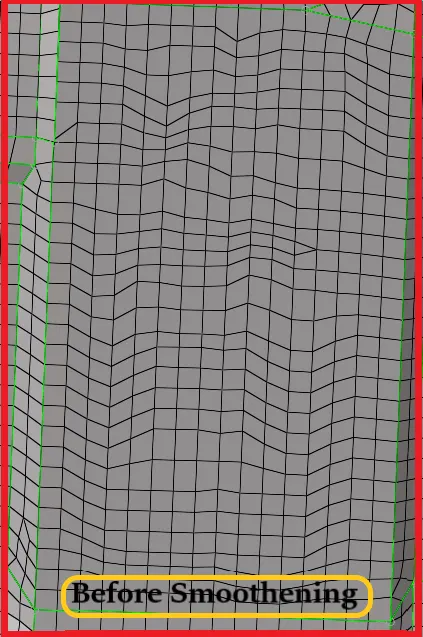
| Figure 66-Before Smoothening. |
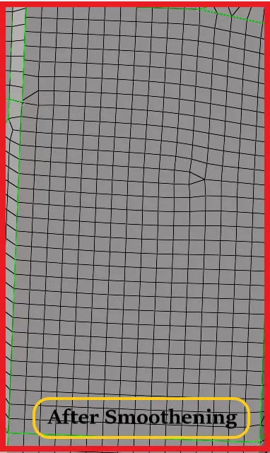
Figure 67-After Smoothening
6:8 Aligning the nodes across edges and align nodes to get proper mesh flow
- After smoothening the elements,Some elements may not be aligned.
- To make them align we can use align nodes tool to align them.
- Go to Geometry >> Node Edit >> Align >> 1st Node >> 2nd Node >> Align.
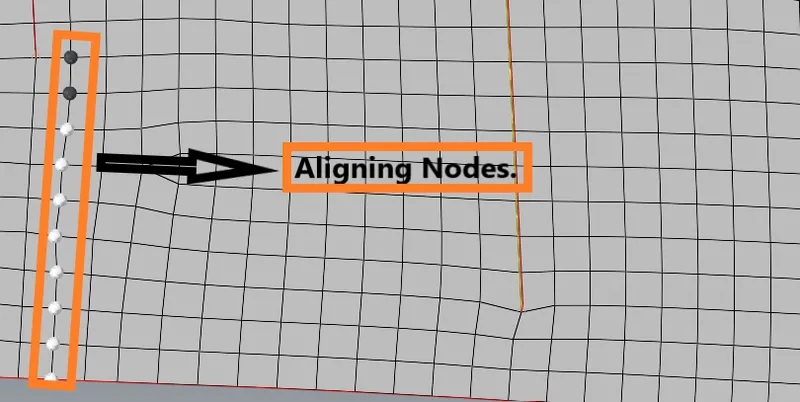
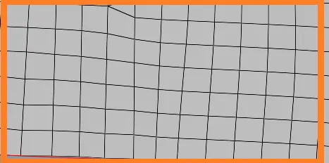
- Align Nodes across edges - If the nodes are not projected to the edges,then you can use project tool to project or align them cross edges.
- To Project go to Tools >> Project >> To Line >> Select Nodes >> Normal Lines.
- It is used to project nodes or points to a line along a user-defined direction or the normal to the line selected.

6:9 Manual Clean Up Using Distance[F4] and Translate[Shift +F4].
- We can use the Distance tool to determine the distance between two nodes/points or the angle between three nodes/points, or to change distances or angles.
- We can also fix the elements failing for the quality like
i) Minimum and Maximum Length
ii) Minimum and Maximum Quad
iii) Minimum and Maximum Tria
iv) Aspect Ratio
- Sometimes we can also fix warpage using distance tool.
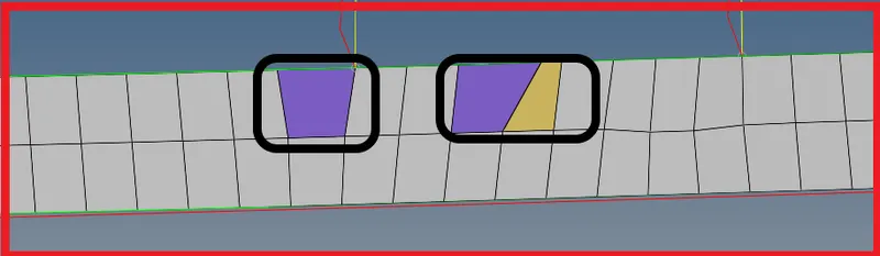
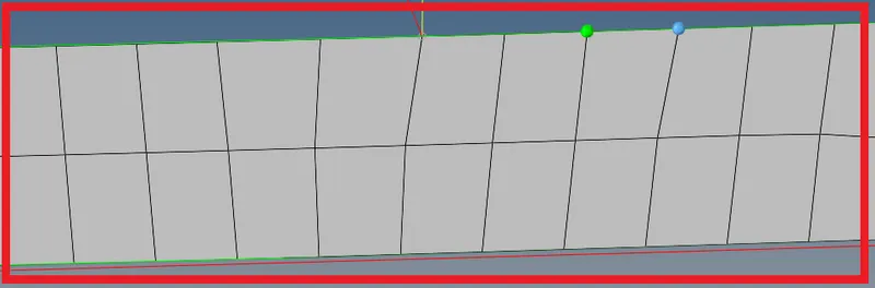
- Similarly we can fix elements failing for min and max quad,min and maax tria ,aspect ratio using distance tool,Sometimes we can also fix warpage.
- But better to use translate tool to fix warpage.
- We will be translating the some warpage angle to the neighbour element,by using translate tool we can easily fix the warpage.
6:10 Fix Warpage
- We can fix warpage by using translate tool.
- We will be translating the some warpage angle to the neighbour element.
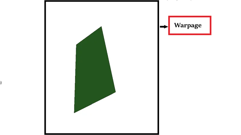
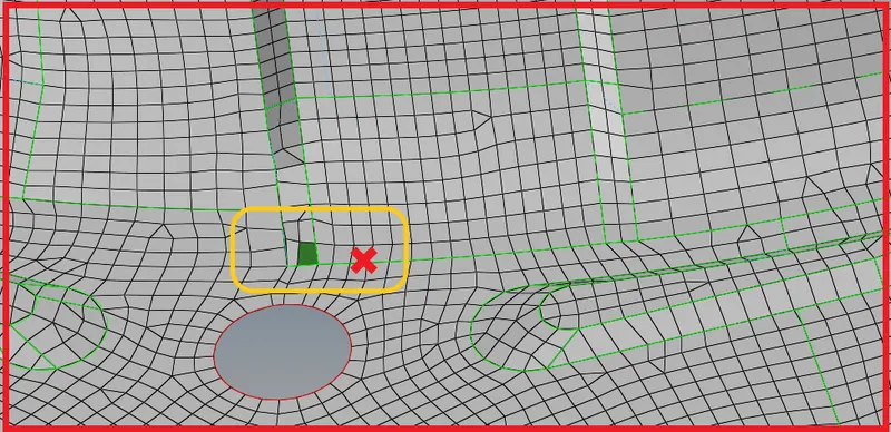
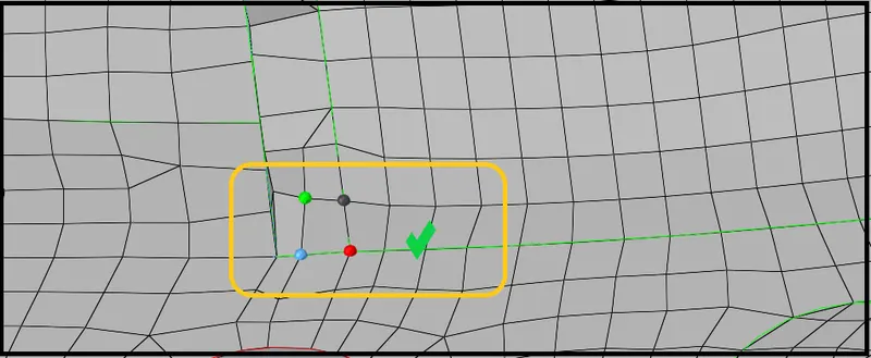
- We can check the warpage angle using check elements [F4].
- Check warpage angle for neighbouring elements also.
- If the neighbouring elements have less warpage angle,we can translate some angle to that element.And then we can clear warpage.
- Go to Tools >> Check Elements >> Warpage.

- If you click on the element failing for warpage,It will show the warpage angle.Here i clicked on the element which is not failing for the warpage angle.So the value is too less and it not failing.
- Now after meshing the entire component,Check for
i) Connectivity [Free Edges]
ii) Duplicates
iii) Normals
i) Check for Connectivity [Free Edges]
- Edge Tool will help us to find this error.
- Go to Too >> Edge >> Elements >> Find Edges.

- If we get the the edges with connectivity,there is no problem,If you get edges without connectivity,then you have to manually connect them with using replace tool.
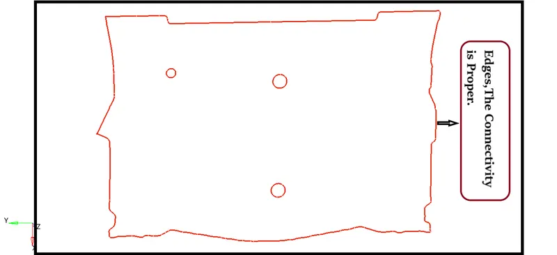
ii) Check for Duplicates
- Now check for the duplicate elements
- To check duplicates,Go to Tool >> Check Elements >> Duplicates.
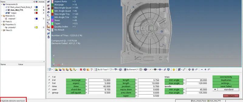
Figure 79-0 duplicates were found
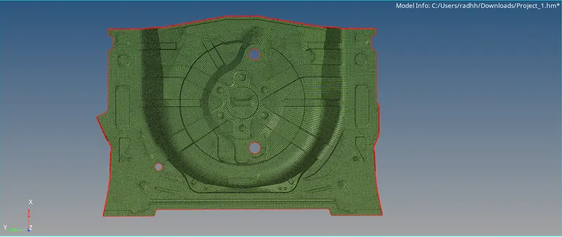
Figure 80-Shrink Elements
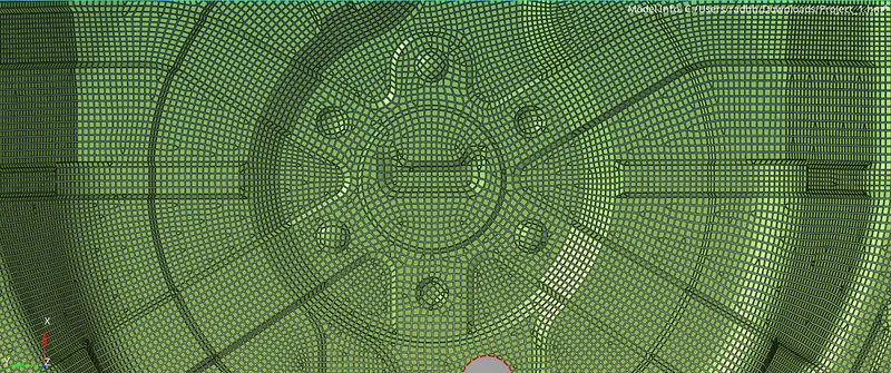
Figure 81-Proper Representation of Shrink Element Mode
iii) Check for Normals
- We can Use the Normals to display and reverse the normals of elements or surfaces. The orientation of element normals can also be adjusted. The normal of an element is determined by following the order of nodes of the element using the right-hand rule.
- Normals can be reviewed showing a vector or by colors. A vector shows in positive normal direction, while the color mode shows the positive side of a shell or surface in red and the negative side in blue.
- To check normals go to Toolbar >> Mesh >> Check >> Elements >> Normals
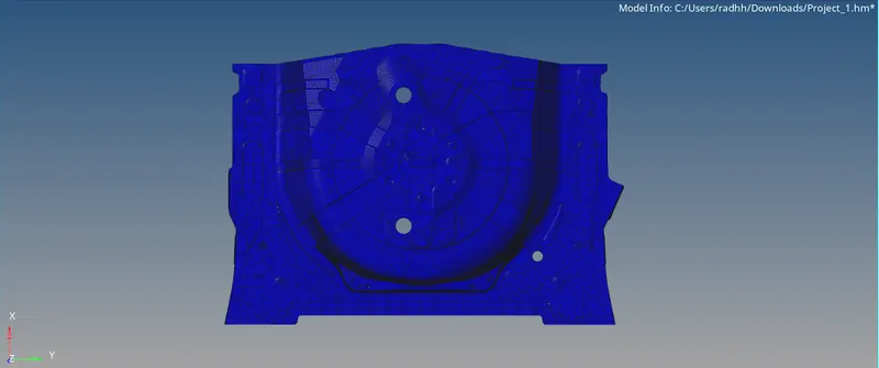
Figure 82-Checking for Normals View 1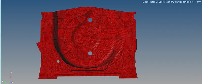
Figure 83-Checking for Normals View 2
Phase 7 - Assigning Thickness to the Elements
7:1 Check thickness in geometry
- First check the thickness in every region and then assign a thickness by creating a collectors and organize it to that newly created collectors.
- Check thickness by distance tool or by dimensioning tool.
- Geometry >> Distance >> Two Points >> Point1,2.
- Geometry >> Dimensioning >> Point1 >> Point 2
7:2 Assign Property to the Components
- First Create a property on the browser.
- To create a property,Right click on browser >> Create >> Property.
- After Creating a property rename it and start assigning thickness to the components
Result -
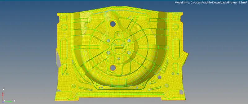
- Hence the mid surface has been extracted from the parent geometry.
- Hence there are no surface deformations in the geometry.
- A well connectivity has been established between the surfaces.
- The features have been captured properly.
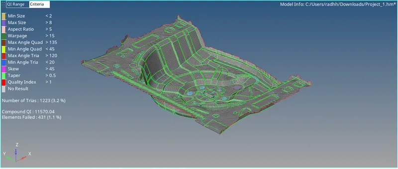
- A good mesh flow have been achieved with the zero elements failing for quality
- Hence tria percentage with 3.2 % have been achieved.
Learning Outcome and Conclusion -
- In this project,I came to know
- How to mesh a complex sheetmetal component.
- How to extract the mid surface manually for the complex sheetmetal components.
- How to clean complex geometry .
- How to generate a proper mesh flow with low tria percentage.
- How to assign thickness to the components.