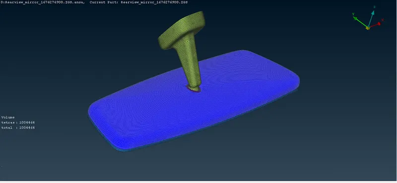
Week- 8 - Solid meshing
Objective:
To mesh the given rear view mirror assembly using 3d tetra mesh by given quality criteria and fix all the errors while meshing.
Quality criteria:
shell elements:
|
S.No |
Quality Criteria |
Value |
|
1 |
Target/Average length |
1 |
|
2 |
Minimum Length |
0.5 |
|
3 |
Maximum Length |
2 |
Solid Elements:
|
S.No |
Quality Criteria |
Value |
|
1 |
Tet collapse |
0.2 |
Procedure:
- First import the given cad model.
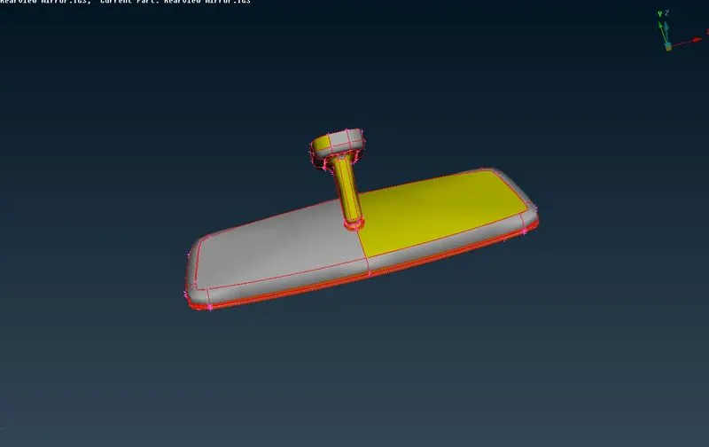
- Now use the topo tool in topo-faces-topo for connect all single cons into double cons.
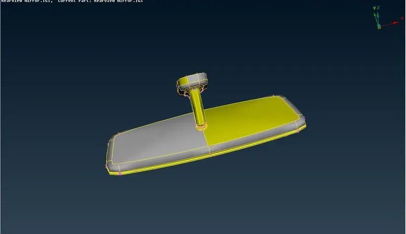
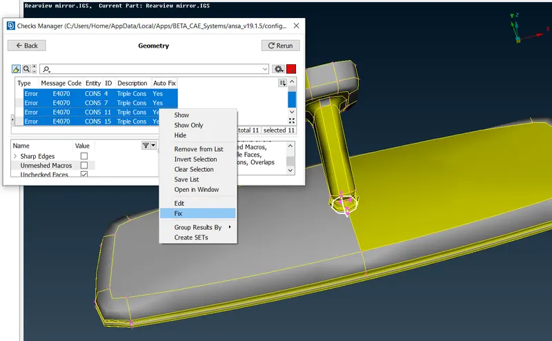
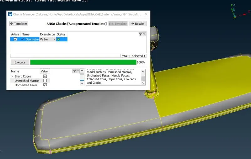
- Intially check the geometry for errors or sharp edges or single cons or crack faces using checks-geometry. select all the errors and fix them.
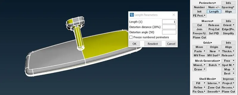
- Now assign the length of 1mm for perimeters and macros for finer resolution using tool mesh-perimeters-length and it will be used for achieve the target length while meshing.
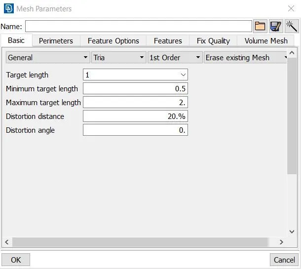
- After all the topo cleanup the geometry. now we go to meshing process. First select the mesh parameters and assign target length as 1mm, min length as 0.5mm, max length as 2mm.
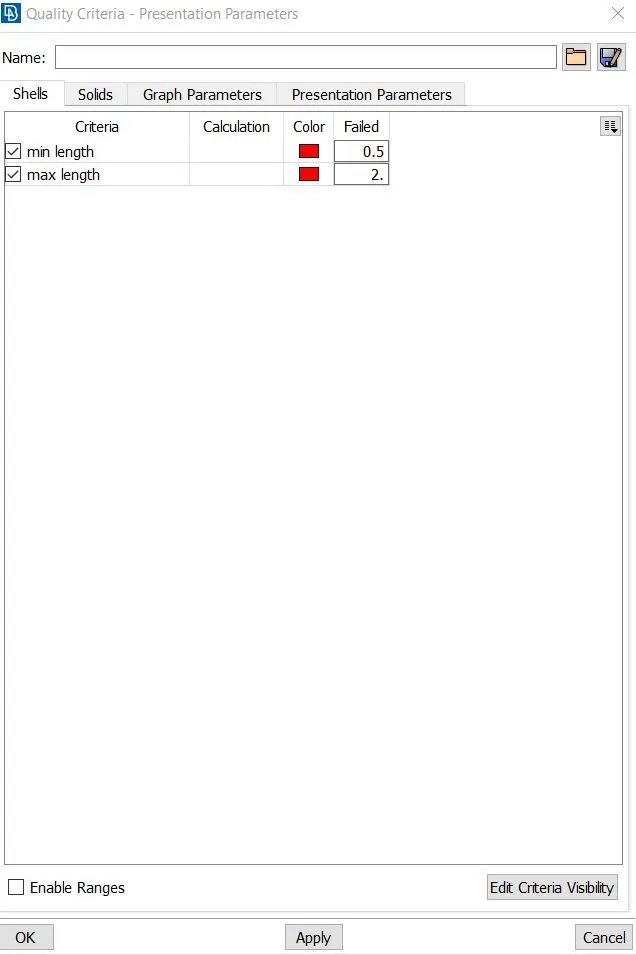
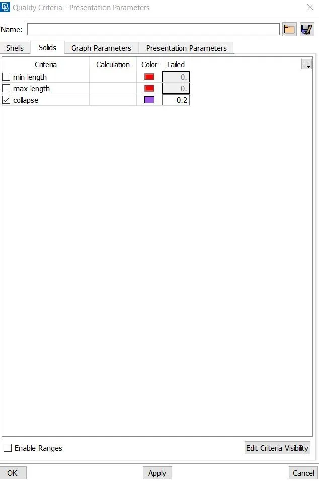
- Select quality criteria tab and assign max length, min length only for shell mesh in shell module and select solid module and assign tet collapse as 0.2mm.
- After that some areas are fail for minimum length while meshing. so we have to suppress some cut lines and create some surface cut in macros using cut tool topo-faces-cut.
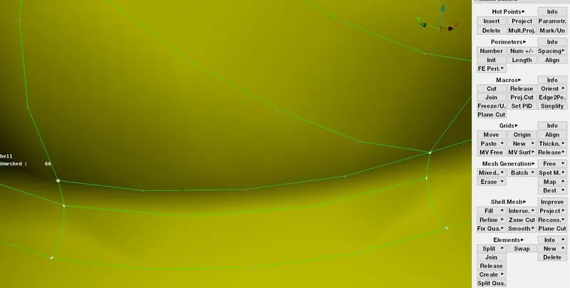
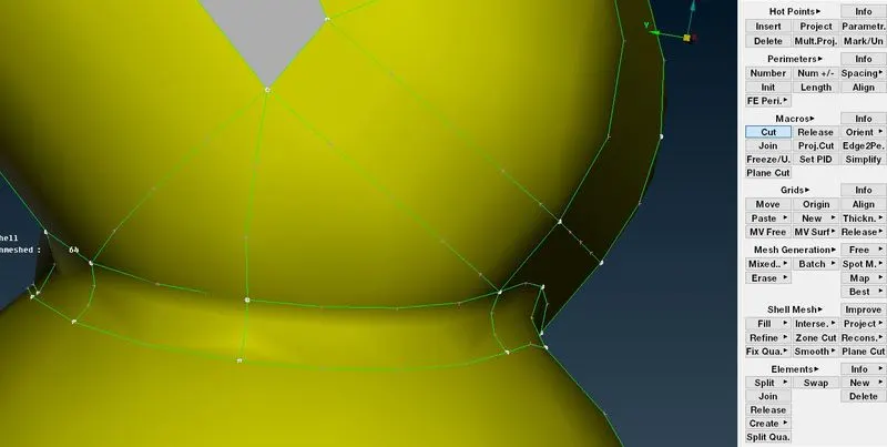
- Now we can go for meshing. select spot mesh tool for mesh the component mesh-mesh generation-spot mesh. some area have feature region such as hemmings, fillets, in that case we should use ortho tria as element type for good mesh flow. we can change this in option list. In some cases, we have flat region, In those we can use trias.
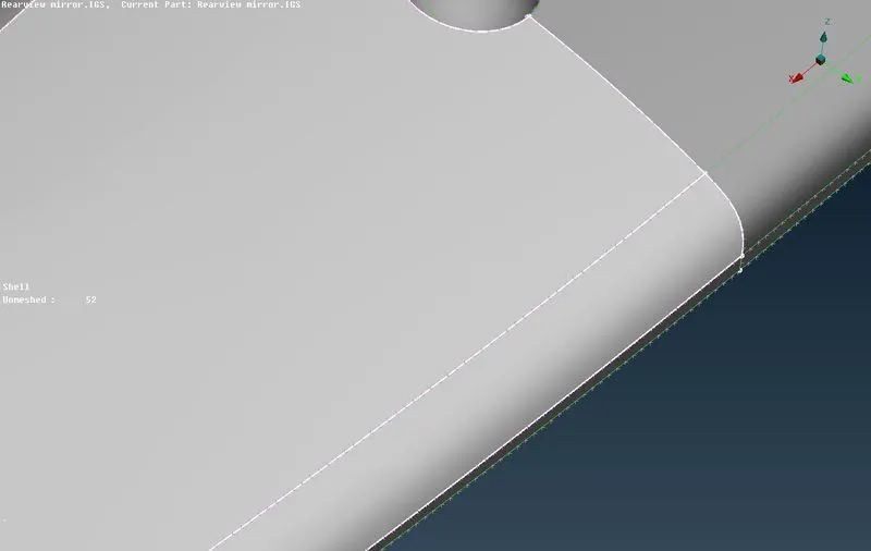
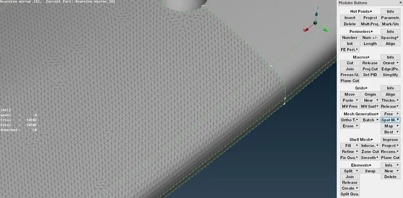
- After meshed the macros, we can reconstruct the mesh for good mesh flow generation using mesh-shell mesh-reconstruct.
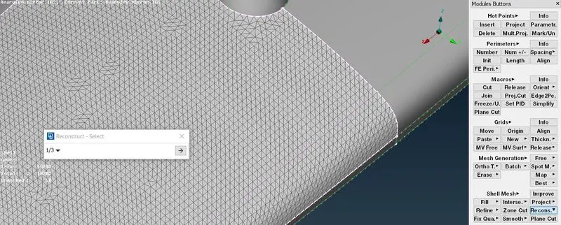
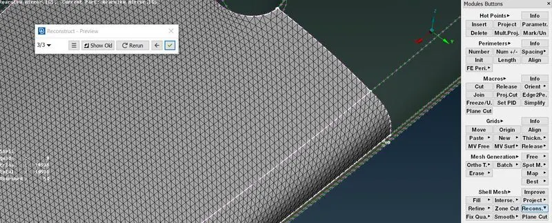
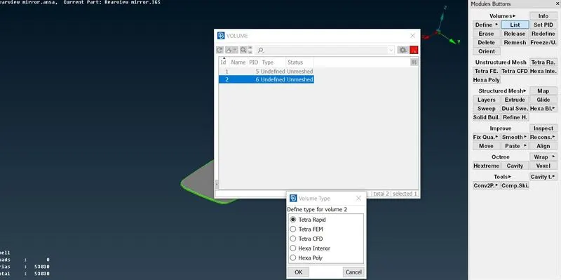
- After creating property for individual component. now we can mesh the shell elements to solid elements using v.mesh-volumes-list. Now rt.click the defined component in list tool. after that select the remesh option. Now the mesh tool module appeared, select the method you want such as tetra rapid or tetra FEM.
Final Images: