Project 1-Meshing of Rear Wheel Holder challenge
Project 1-Meshing of Rear Wheel Holder
1. Aim
- To Generate a mesh on a given model after a proper geometry cleanup and mid-surface generation using Hypermesh.
- Ensure the generated mesh obeys the mentioned quality criteria and the corresponding thickness of each surface assigned to the mesh.
Objective
- Import and perform a geometry cleanup on the given model using Hypermesh.
- Assign thickness and generate a Proper mid-surface with the proper technique.
- Mesh the generated mid-surface and reconstruct the mesh to satisfy the following quality criteria.
- Model Checks
Quality Criteria
| Sl No: | Quality Criteria | Value |
| 1 | Target Element Length | 5 |
| 2 | Aspect Ratio | 5 |
| 3 | Skewness | 45 |
| 4 | Warping | 15 |
| 5 | Taper | 0.5 |
| 6 | Min. Length | 2 |
| 7 | Max. Length | 8 |
| 8 | Min. Angle Quad | 45 |
| 9 | Max. Angle Quad | 135 |
| 10 | Min. Angle Tria | 20 |
| 11 | Max. Angle Tria | 120 |
| 12 | Tria % | 10 |
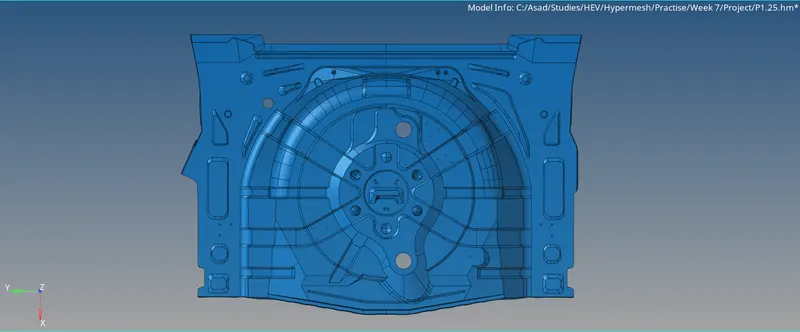
Fig 01: Isometric View Of Model.
Step 2: Geometric Cleanup and Extracting Midsurface.
By inspecting the model, the geometry is complex and has many surfaces, faces and features that should be covered on the mesh. So the auto cleanup will not give any proper cleaning. So we have to go for manual cleanup. We can clean the geometry manually using tools provided in the quick edit panel or surface edit. After performing proper operations like Toggle, Washer Splits, Filling and Deleting Surfaces and other functions, the geometry is now cleaned.
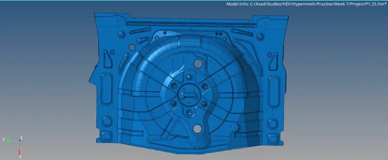
Fig 02: Manually Cleaned Geometry
Then, the mid-surface is extracted using the mid-surface option. Here we choose the extraction option as 'offsets'.
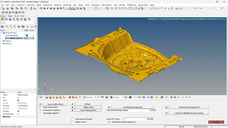
Fig 03: Mid Surface Extraction
By inspecting the mid-surface, the mid-surface needs some cleaning. There should be some surfaces that are missing, the 'ruled' option or 'filler surfs' can address it.
Step 3: Property, Material, Measuring Parameters and Quality Criteria
By measuring the thickness (Using projected nodes on the surfaces), the thickness value is found that and it is equal to 0.75 Units. Create the property and the material for the mid-surface based on thickness and add to the mid-surface component. Then we have to assign the measuring parameters and quality criteria for the mesh.
For adding quality criteria,
- Preferences >> Criteria File Setting >> Input the Mentioned Quality Crieria >> Ok
For Measurement Parameters,
- Preferences >> Parameters File Setting >> Input the Target Element Length >> Ok
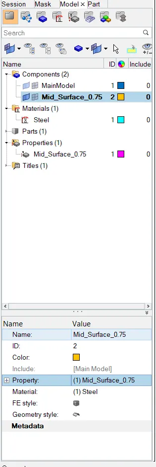
Fig 04: Property and Material
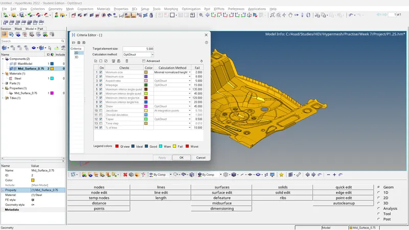
Fig 05: Quality Criteria
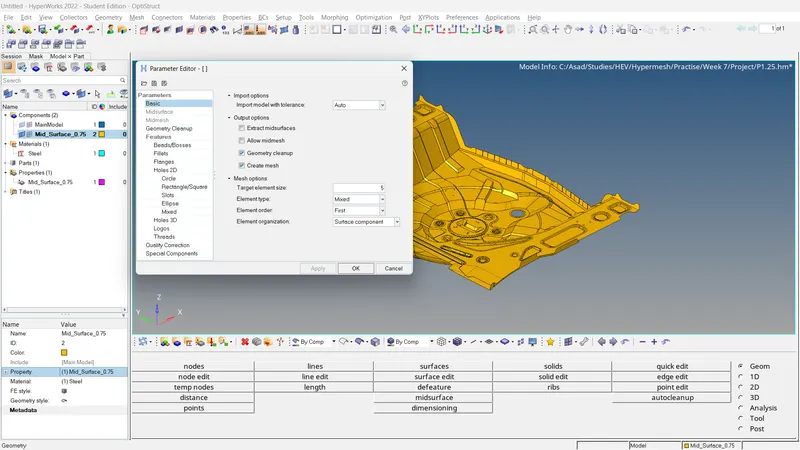
Fig 06: Measuring Parameters
Step 4: Meshing the Surface
As we mentioned earlier, this geometry is complex in structure and has a lot of small features that should be covered. So we have to mesh surface by surface. Also, adjusting the number of nodes for good mesh flow.
- 2D >> Automesh >> Select Surface >> Ok.
The mesh flow should be improved especially in feature areas. For that, we can use these functions,
- 2D >> Rebuilt >> Select the mesh elements which to be reconstructed.
- 2D >> Edit element >> Create/Combine/Split
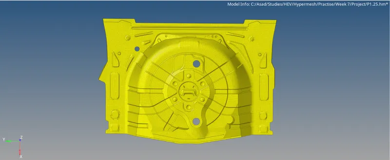
Fig 07: Generated Mesh
After correcting the mesh flow, the element quality should be checked.
- 2D >> Quality Index >> Cleanup Tools
Using the following tools, Place nodes/Smooth/Modify holes and washers/Split and Collapse Edge/Swap edge/Drag tria element/node optimise/element optimise/split quad element/combine tria element, we can simply modify elements to obey element criteria.
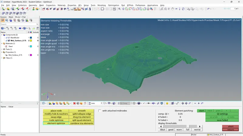
Fig 08: Quality Index
Also, the elements can be checked by following,
- Tools >> Check Elements >> Edit Criteria >> Click To See Plots
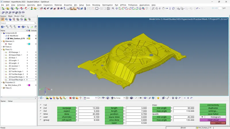
Fig 09: Element Checks And Their Plots
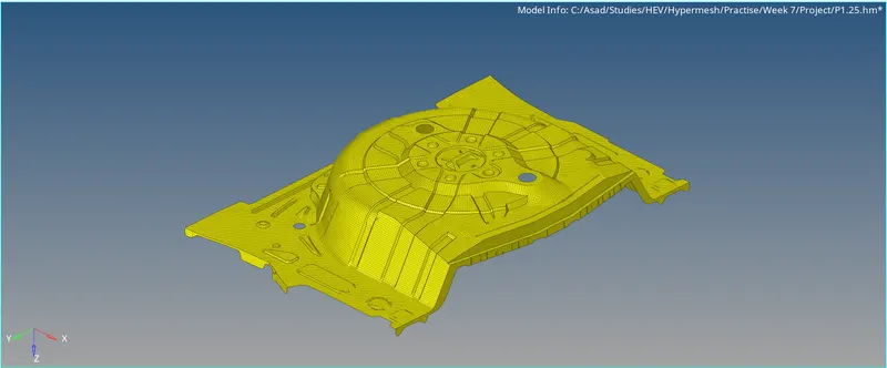
Fig 10: Final Mesh
Step 5: Model Checks
Check For Free Edges And Equivalence
- Tools >> Edges >> Select Elements >> Adjust The Tolerance Value (~0.5) >> Find edges.
If edges are present inside the geometry (free edges), it will affect the model. In order to remove the free edges, we can delete edges or recreate elements where free edges are present. Also, we can check for the equivalence to remove the gap between the elements.
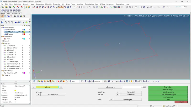
Fig 11: Edges
If edges are present inside the geometry (free edges), it will affect the model. In order to remove the free edges, we can delete edges or recreate elements where free edges are present. Also, we can check for the equivalence to remove the gap between the elements.
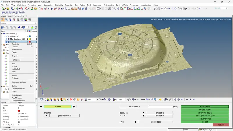
Fig 12: Check For Equivalence
For finding duplicates,
- Tools >> Check Elements >> 2D >> Duplicates
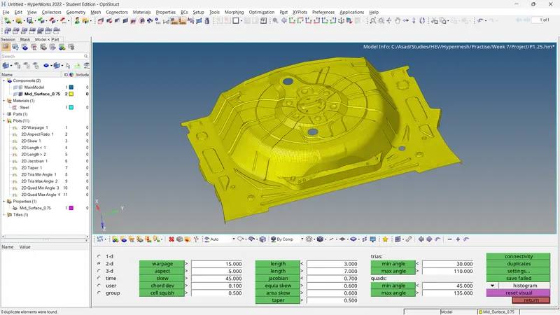
Fig 13: Check For Duplicates
Checking connectivity between elements and the presence of duplicate elements,
For Connectivity
- Tools >> Check Elements >> 2D >> Connectivity
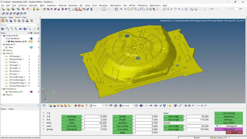
Fig 11: Check For Connectivity
Check For Normals
- Tools >> Normal >> Elements >> Color Display >> Vector Display >> Size= 100 >> Display.
If any of the vectors have opposite directions, it can be corrected by Using the 'Adjust' option.
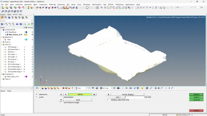
Fig 12: Check For Normals
Check For Penetration and Dependency
For penetration/intersections checks,
- Tools >> Penetration >> Select Elements >> Check
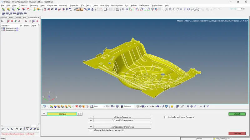
Fig 13: Check For Penetration/Intersections
For dependency checking,
- Tools >> Dependency >> Select Elements >> Dependency
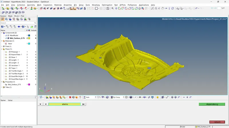
Fig 14: Check For Dependency
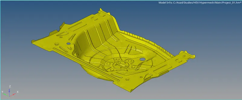
Fig 15: Final Result
4. Conclusion
- The mid surface of the given model is generated and assigned properties, material and add quality criteria and target element lengths.
- The meshing and reconstruction of generated mesh are completed.
- Model checking is finished.
5. Results
- For the given model, the mid-surface is extracted and mesh generated. The generated mesh satisfies the following quality criteria and the model checks are completed.