Project 1-Meshing of Rear Wheel Holder challenge
OBJECTIVE
To mesh the given floor panel geometry through after generating its midsurface. To also ensure that mesh is of the highest quality (following given quality criteria) with a low number of trias and good mesh flow.
PROCEDURE
1. First thing to do is to make sense of all the collectors, which this component has several of. We can combine all the collectors into one by moving all of them to the first collector and then deleting the empty ones. This will help prevent any prospective confusion. This is done using the 'organize' tool (Tool > Organize). We need to select the surface that needs to be moved and the destination surface and we can go ahead and click move,Next, we can create a new collector and we'll name it 'Midsurface' from the collector menu by right-clicking and selecting create > component.
2. Since the entire component has almost the same thickness, we can go ahead and generate the midsurface manually from the bottom. This is due to the complexity of the geometry in certain regions. For this, we will need to measure its thickness. Which is 0.75 mm. (Thickness tool can be accessed by pressing F4). We need this for the manual creation of the midsurface. And this is done using the offset tool under surface edit.
3. Before carrying out the next step, we need to ensure that the newly created midsurface component is our current component. (We can make a component the current one by right-clicking the particular collector and selecting the 'make current' option).
4. The offset tool requires a measurement half of the thickness. Which would be 0.375 mm in this case. The offset tool can be accessed through Geometry > Surface Edit > Offset. We can select any one face from any one of the faces. And then, right-click surfaces and select 'by face'. When this is done, the entire face is selected,We can verify the vector normal too by clicking the vector normal as shown in the picture. This lets us know the prospective direction of the offset. We can reverse it if it is in the opposite direction using the 'reverse normal' option.
5. As can be seen in the above screenshot, there is some cleanup that is required (free edges have appeared and are marked in red). We can make use of the toggle tool to stitch up gaps between surfaces. That will be the reason for most of the free edges seen here. Toggle option can be accessed through Geometry > Quick Edit > Toggle Edge. One of the free edges is then clicked to stitch the gap.
6. After cleaning up the midsurface and before meshing, firstly, the quality parameters are entered in the criteria file settings (Preferences (Toolbar) > Criteria File Settings).
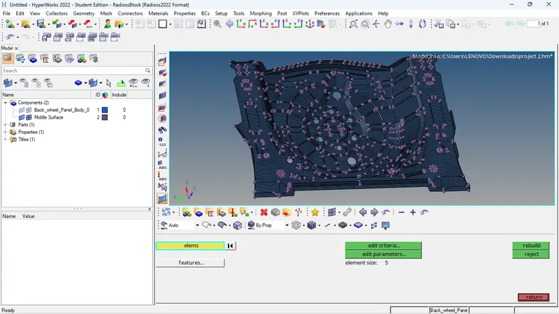
7.After the mesh is created, we can clean the mesh using various tools. Primarily, we will be using the element optimize tool, the drag tria tool and to an extent, the swap edge tool. These are accessed from the quality index section in the 2D menu. Also, after dragging trias, smoothing will be required. It can be accessed through 2D > Smooth.
8. We will now check for equivalency by going to the edges section in the tools menu and previewing equivalence for varying tolerances (ranging between 0.2 mm to 2 mm). This is to ensure there are no misaligned elements or free edges, which we can also check using a different option in the same section. The preview equivalence option shows us the nodes that require equivalencing. They are rectified by clicking the 'equivalence' option in the menu. If some nodes haven't been tended to, it may require manual fixing, using the replace node option (F3).
9.Finally, we can assign a thickness for each of our midsurface, which is 0.75 mm. We can do this by right-clicking and creating a component in the component tree. After a property is created (and named 'Thickness'), we can go to its section in the bottom left and scroll down to assign the aforementioned thickness.
RESULTS
Therefore, the given floor panel was meshed after its midsurface was extracted. Meshing was carried out as per required quality criteria and it was ensured that the mesh flow was as smooth as possible. There were failed elements due to having to ensure proper surface capture.