Project 1-Meshing of Rear Wheel Holder challenge
Project 1-Meshing of Rear Wheel Holder challenge
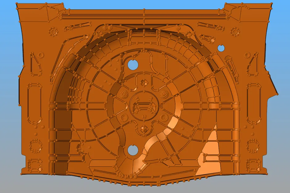
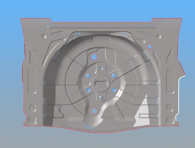
Aim: To perform preprocessing on the given Rear Wheel Holder [Spare Wheel Floor Panel] Sheet Metal component using hypermesh preprocessing software.
Objective
· To generate the mid surface manually and do a geometry clean-up on the component.
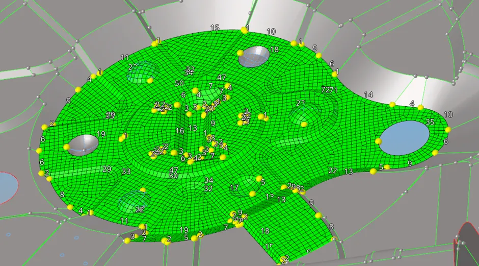
· To generate a mesh and to get a proper mesh on the given component.
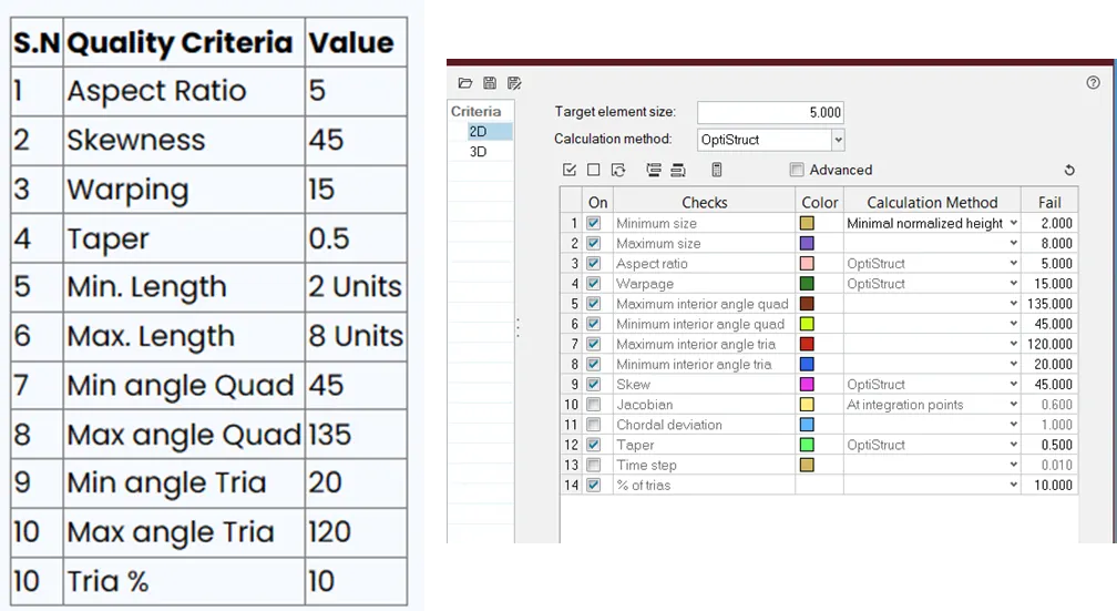
· To check the element's quality according to the given quality criteria.
· To assign a thickness for the component.
Procedure:
1] Given.IGS file is imported to the hypermesh.
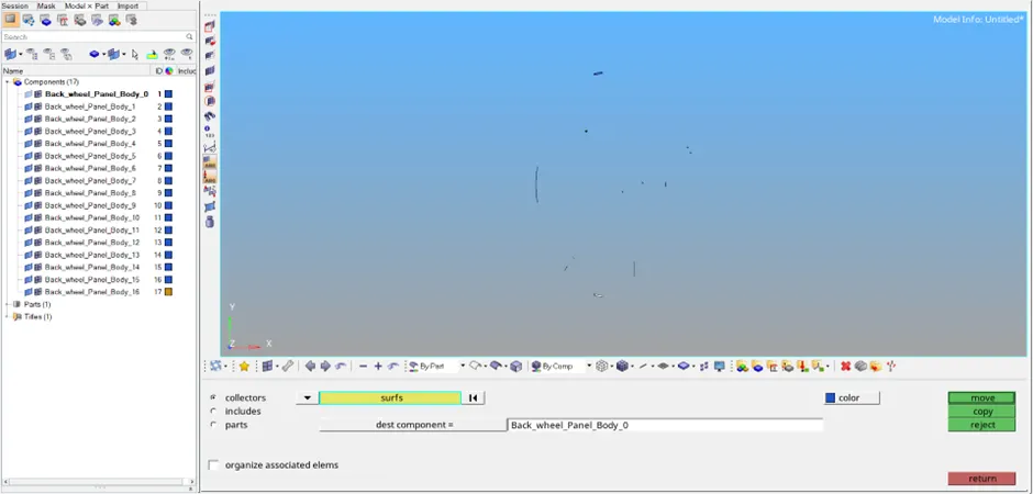
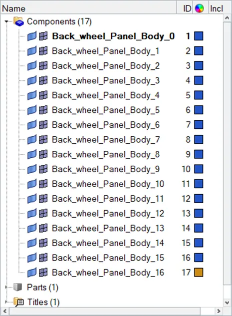
2] This model has 17 different components; it is managed as a single component by using the organise tool.

3] Damaged geometry with free edges must be corrected by using the proper tools in the quick edit panel and surface edit panel.
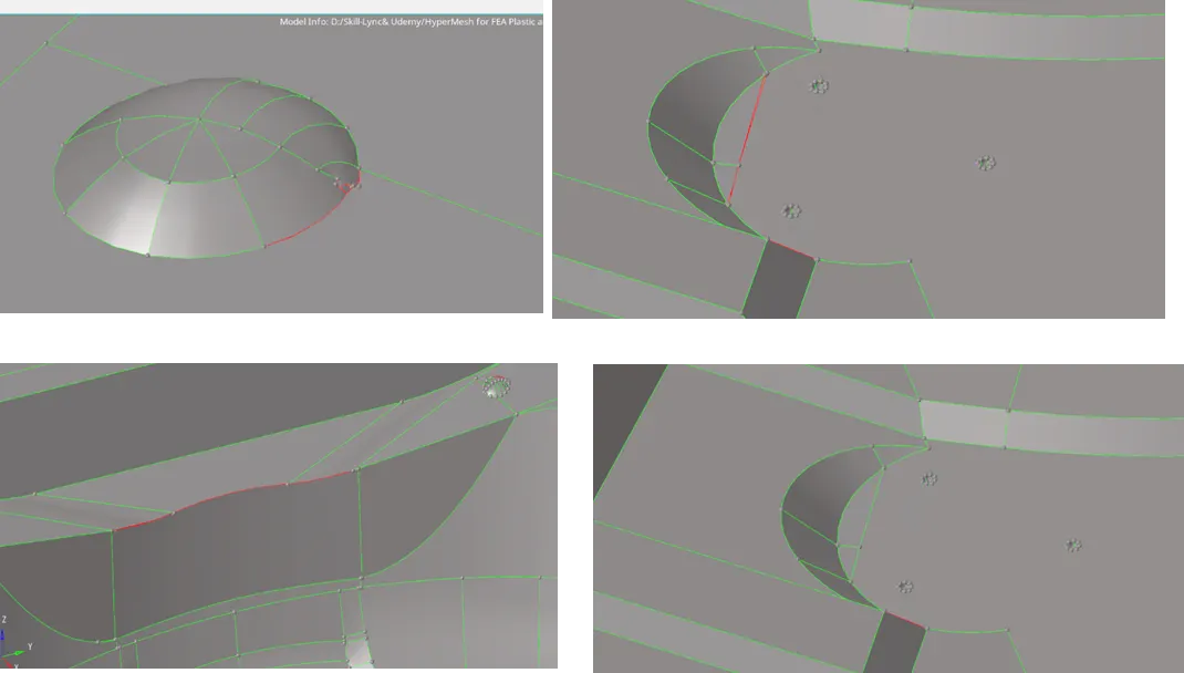 4] Commands like toggle edge, filler surface, delete surface, replace point, add/remove point should be executed in proper damaged places of the geometry.
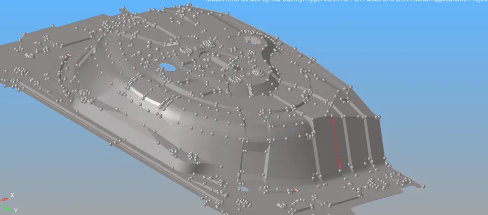
5] Free edges can be identified by the proper visualisation also and further, it can be corrected by the proper quick edit tools.
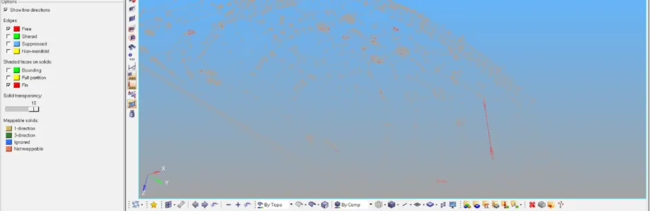
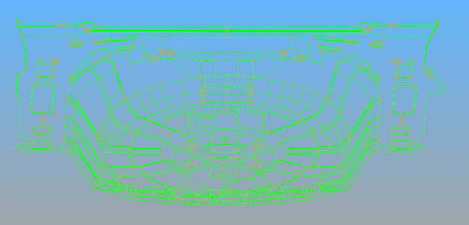
6] Finally geometry cleanup should be done properly, and the geometry should not have any free edges.
7] The given geometry is considered sheet metal as it has the same thickness all over the geometry.
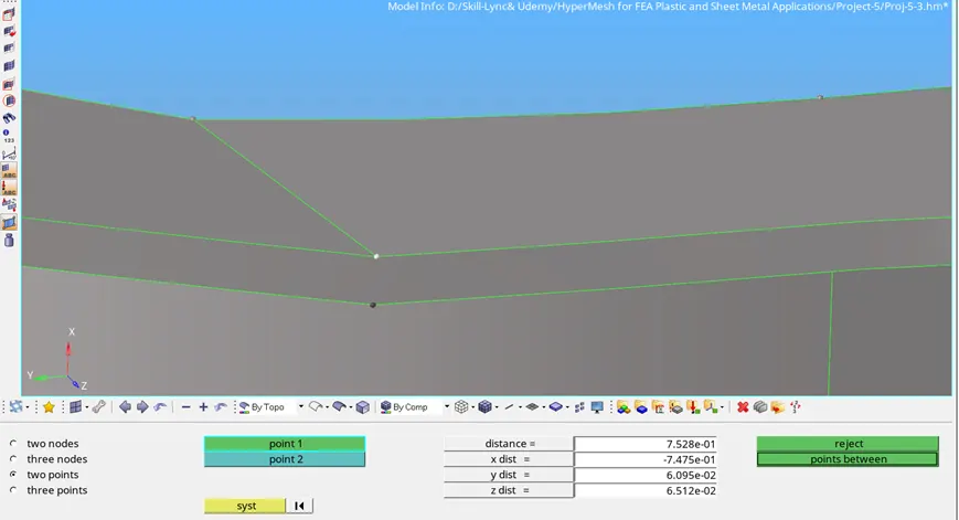
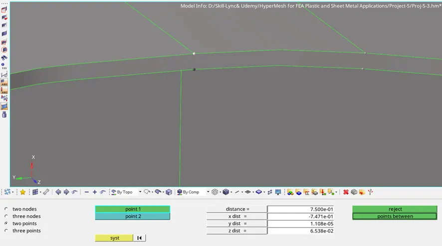
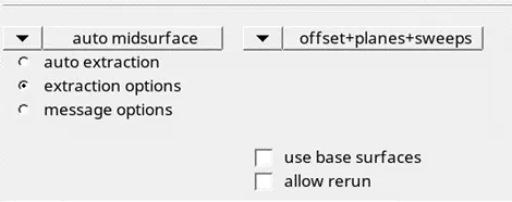
8] Auto Mid surface is extracted from the geometry by selecting all the surfaces. And offset+planes+sweeps option has to be selected.
9] After midsurfacing the geometry also has some of the errors those errors have to be rectified as like geometry.
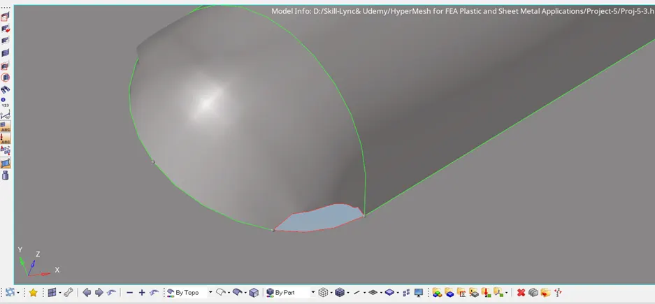
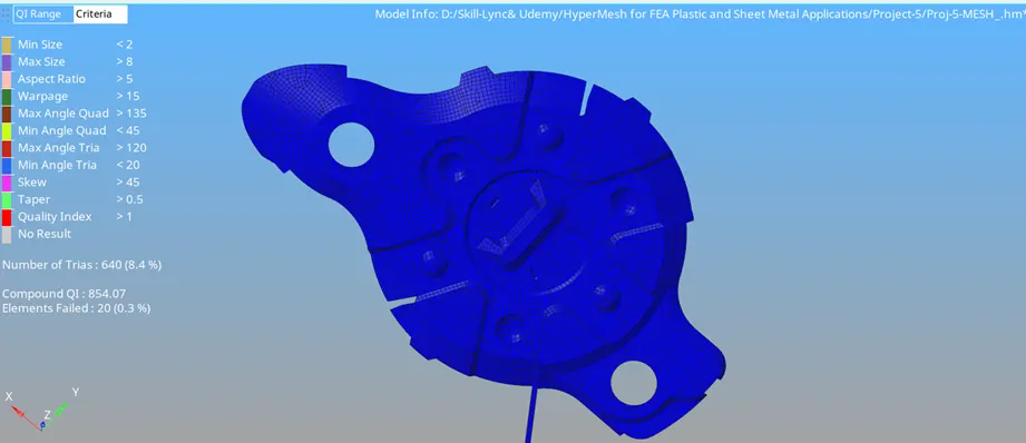
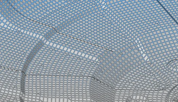
10] Damaged mid-surface with free edges must be corrected by using the proper tools in the quick edit panel and surface edit panel.
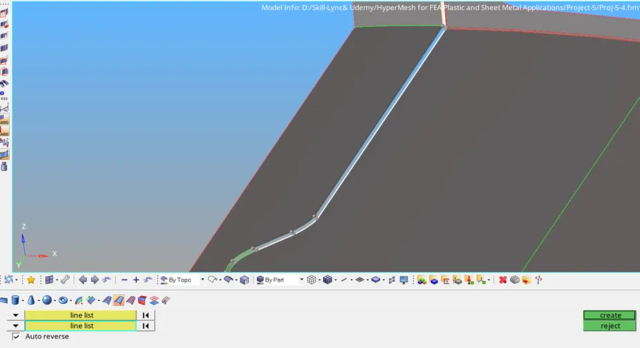
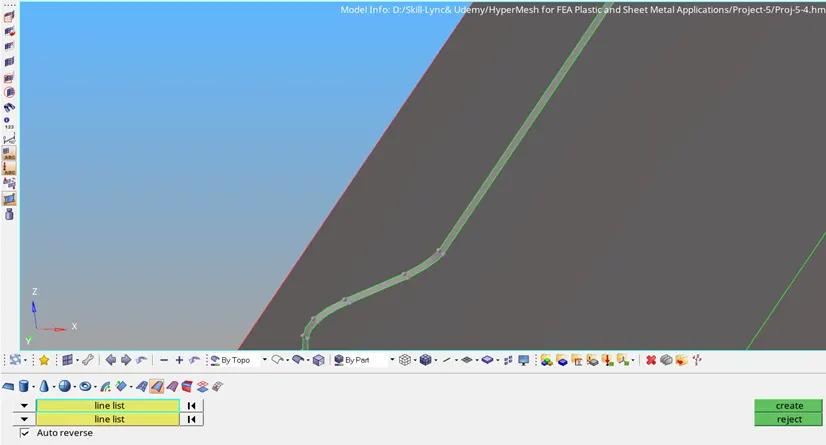
11] Some surfaces are corrected and generated using Surfaces---Ruled---Lines list tools also.
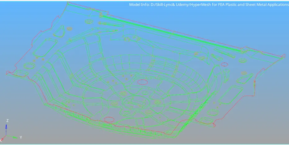
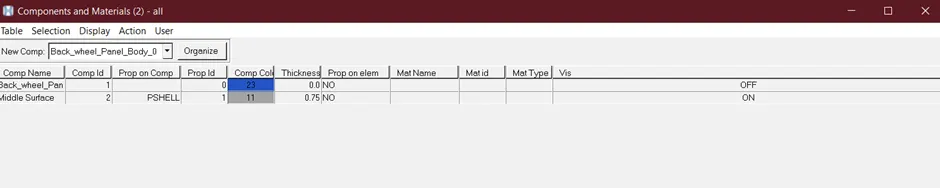
12] Mid-Surface is generated and corrected properly by using various tools like Toggle Edge, Filler Surface, Filler Surface, Ruled Surface etc.
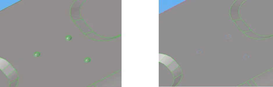
13] Pin holes surfaces can be removed and neglected, those surfaces are filled and toggled.
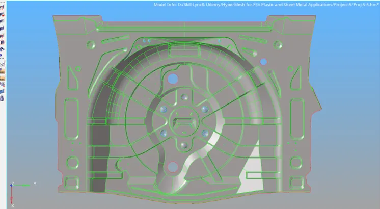
14] Mid surfaces are corrected properly, no free edges present in the middle.
15] Quality criteria have to be maintained as per the given geometry.
16] Meshing can be started with good flow and low tria concentration.
17] Mesh element orientation can be checked by using the normal command by visually the colour.
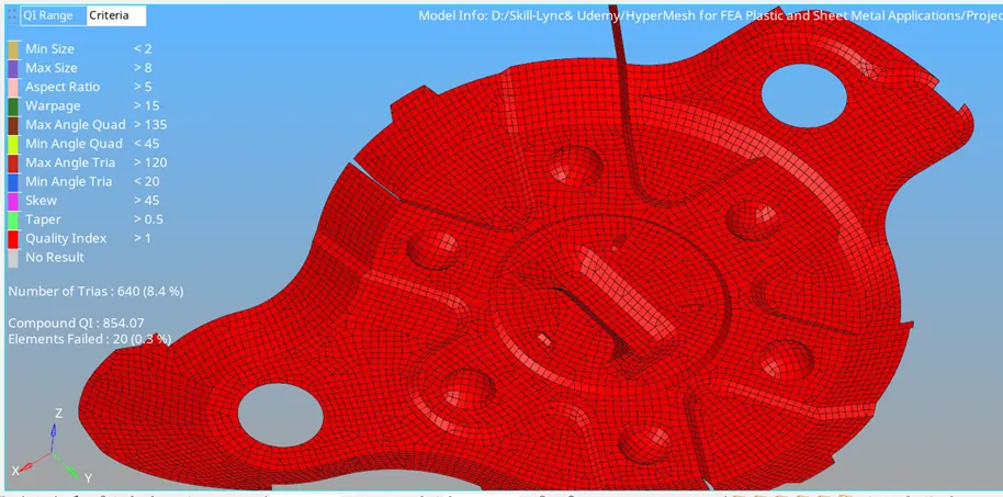
18] Meshing has to be done to the entire mid-surface properly, by using proper tools like QUALITY INDEX, smooth, combine tria elements, element optimize, node optimise, swap edge, Rebuild mesh etc.
19] Duplicate elements are avoided using the shrink element tool.
20] After proper meshing the thickness has to be assigned to the mesh by creating property.
Course Outcomes:
- Proper geometry cleanups
- Proper mesh flow
- Low tria concentration
- Assigning thickness
Result:
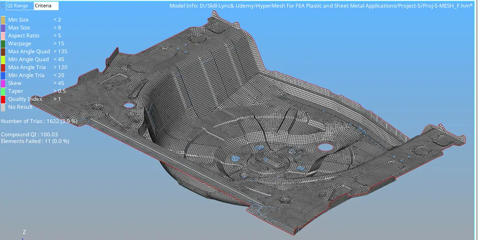
Meshing on the given component with low tria concentration and proper mesh flow is done and also the quality of the mesh passed all the given quality parameters.
https://drive.google.com/file/d/19-jprqW1WQQ9kBvEhP63BcbuDgsUrMrc/view?usp=drive_link
Note: File size exceeds the 20MB. So I request you to find the drive link for the download.
https://drive.google.com/file/d/19-jprqW1WQQ9kBvEhP63BcbuDgsUrMrc/view?usp=drive_link

https://drive.google.com/file/d/19-jprqW1WQQ9kBvEhP63BcbuDgsUrMrc/view?usp=drive_link