Project 1 - Meshing of Floor Panel
Project-1 Meshing of Floor Panel
Aim:
For the given (FLOOR PANEL) CAD model geometrical cleanup, mid-surfacing and meshing are performed for the given quality criteria.
Objective:
- Proper geometry cleanups (Ease access of mid-surfacing).
- Auto Mid-Surfacing (Casting/Extrusion).
- Mesh Flow correction by using PID Region.
- Meshing the model as per the given QC without any OFF elements.
Procedure:
1) Importing the (IGS file) model into the ANSA.
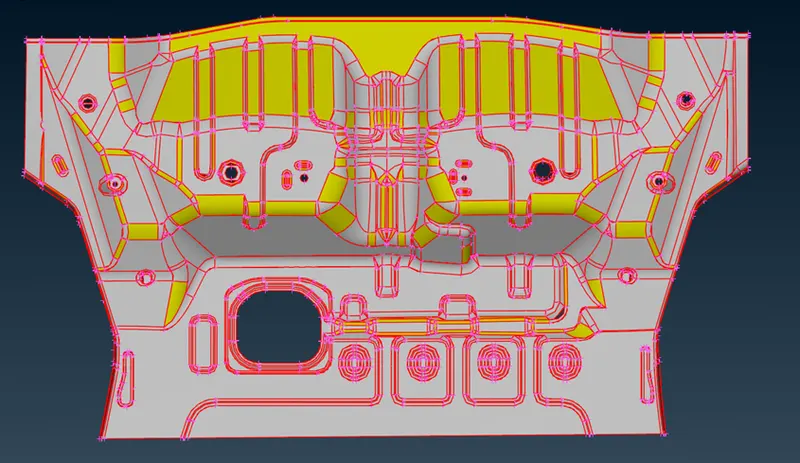
2) To improve edges and curves feature qualities, in classic mesh LENGTH---Perimeters and Macros are adjusted to 1 to get the good finish of the solid model.
3) Topo command is used for the stitching of curves with their neighbouring edges. It will turn red (Single cons) to yellow (Connected cons-2), and the orient command is performed for the proper face alignments.
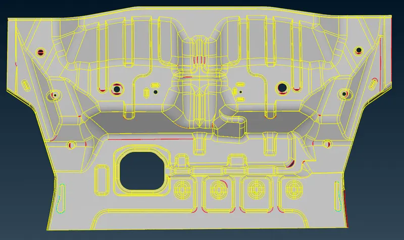
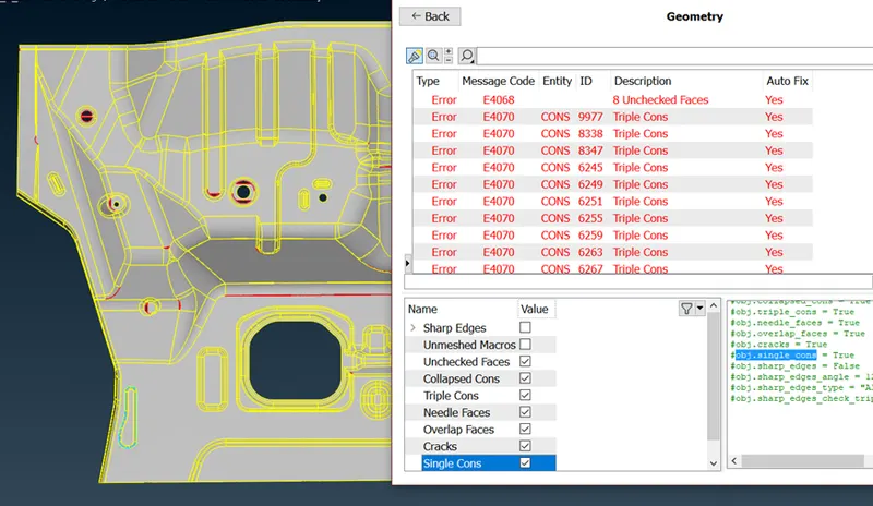
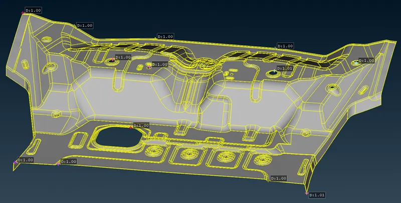
4) Geometry checks are done, which corrected automatic FIX as well as manually. This geometry had many errors cleaning up took some time. Corrections are done for the entire geometry without any errors because with some errors auto mid-surfacing and meshing cannot be done in a good manner.
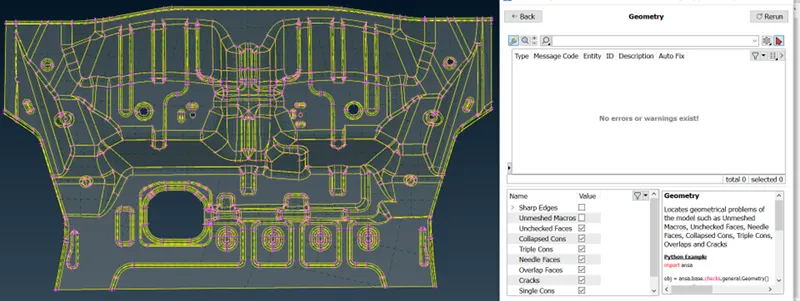
5) After correcting every error, the given model can be investigated whether sheet metal or plastic. It is determined as the sheet metal, containing the same thickness (1mm) throughout the model.
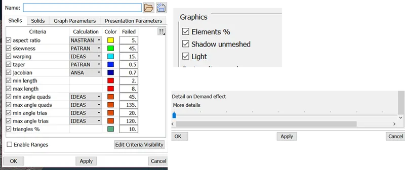
6) Quality criteria file is saved as per the given model.
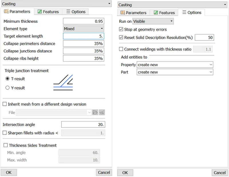
7) As this model is identified as a single large component auto mid-meshing (CASTING/EXTRUSION) process can be done for saving the time period for the project. Due to large geometry CASTING/EXTRUSION process will take some time (comparatively low time upon offset method) to complete the auto mid-meshing process.
8) After the process is completed mid-meshing correction can be done as it has too many off elements and trias are present which has to be avoided.
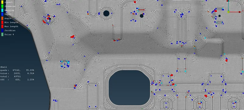
9) Getting rid of the OFF elements and trias proper mesh flow strategies has to be followed along with the appropriate tools.
10) OFF elements and proper mesh flow are to be generated by using proper areas with INOT command.
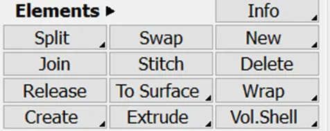
11) Commands like SPLIT, SWAP, JOIN, PASTE are used to correct the mesh flow manually for the optimized quality.
(Paste option in GRIDS)
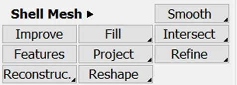
12) Commands like SMOOTH, RECONSTRUCT, RESHAPE, IMPROVE, and OPTIMISE are used to correct the elemental errors for good flow with the mesh.
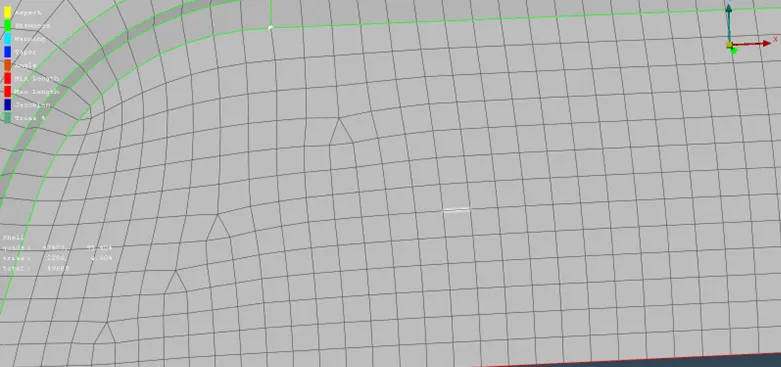
13) Mesh corrections cannot be done in a single shot it will take some time.
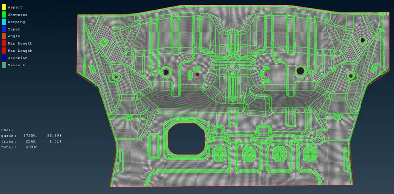
14) Final checks are done with mesh flow, OFF elements status etc.
Course Outcome
- Large geometry cleanups.
- Auto Mid-Meshing using CASTING/EXTRUSION.
- PID region and INOT commands for the mesh flow corrections.
Results:
The given (FLOOR PANEL) CAD model geometrical cleanup, mid-surfacing and meshing are performed with average flow criteria as per the given quality criteria.
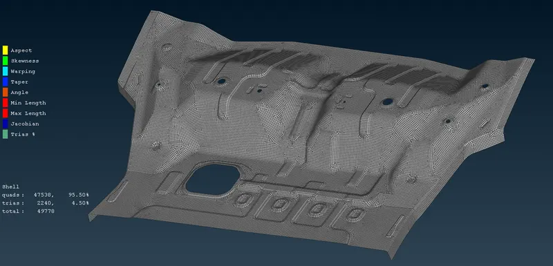
Note: Meshing and the corrections are done quickly compared to the previous challenges to perform quickly and for upcoming tool test sessions. Still mesh flow can be improved but due to lack of time, I just satisfied at least the given quality criteria.