Project 1 - Meshing of Floor Panel
Project - 1
MESHING OF FLOOR PANEL
Report
Aim
Prepare post-processing for Floor panel by eliminating geometrical errors, using ANSA pre-processing software.
Objective
For the given sheet metal CAD model of the Floor Panel of the vehicle,
- to check for the geometrical errors
- take the mid surface.
- mesh the Surfaces with the given 2D element Quality criteria.
- assign thickness.
Quality criteria
Target Element Length = 5 Units
|
Sl. No. |
Quality Criteria |
Value |
|
1 |
Aspect Ratio |
5 |
|
2 |
Skewness |
45 |
|
3 |
Warping |
15 |
|
4 |
Taper |
0.5 |
|
5 |
Min. Length |
2 Units |
|
6 |
Max. Length |
8 Units |
|
7 |
Min angle Quad |
45 |
|
8 |
Max angle Quad |
135 |
|
9 |
Min angle Tria |
20 |
|
10 |
Max angle Tria |
120 |
|
10 |
Tria % |
10 |
Procedure
- Open the cad model in ANSA V23.0.0 using the file>open option.
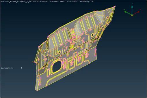
2. Perform topo on it, as the model is too distorted after importing from different software.
3. Geometry Check and execute RUN.
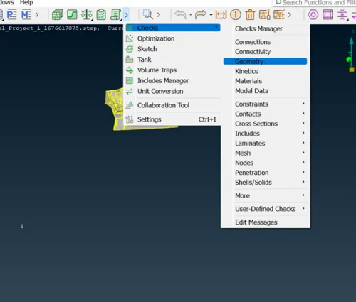
4. We can see that after executing Geometry check, it is showing 100% OK.
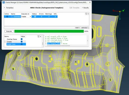
5. Go for the Length option from the mesh module to find out the actual geometry of a model.
Box select the model and enter the value for perimeter as 5.
Box select the model and enter the value for macro as 5
6. Mid-surface generation
We can use both skin option method or offset. But there are certain regions where we need to make sure whether the feature has been captured properly. If not should use the offset method.
Classic TOPO - Faces - Offset
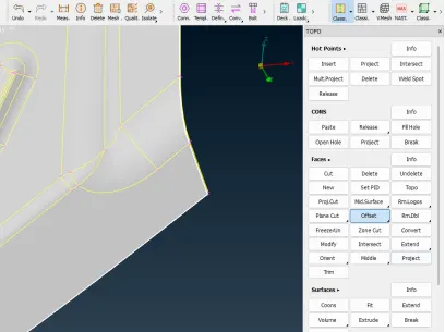
We can use feature angle option for selection which will help to select faces with less time.

Check the selected faces and hit middle click. Provide the offset value vased on the Arrow projecting.
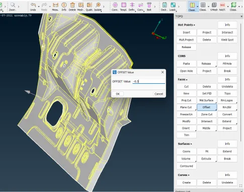
Since the arrow is projecting outwards, I have given “- 0.5”.
7. Mid-surface in critical areas
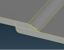
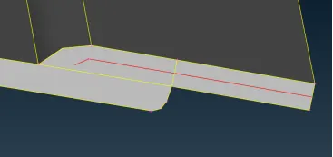
8. Set PID for the Mid-surface made.
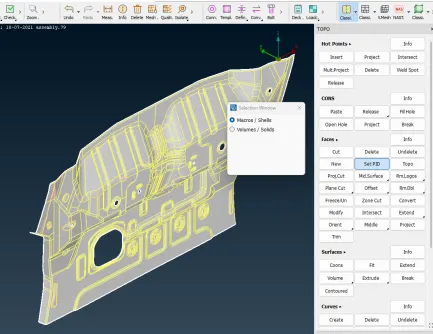
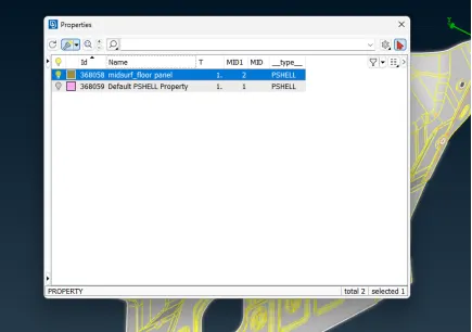
9. Assign Thickness to the mid-surface.
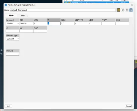
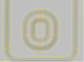
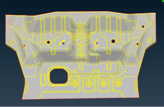
10. Before starting meshing, find out the critical regions where the elements will fail in minimum element criteria. We should not disturb the geometry only suppressing the feature lines where elements may fail.
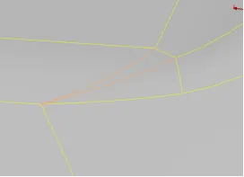
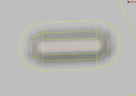
11. Before starting meshing perform Classic Topo-Faces-Orient.
12. Perform TOPO, Classic TOPO - Faces - TOPO
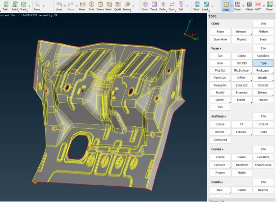
13. Now we need to prepare proper construction line for better mesh flow .
14. After generating all the mid-surfaces, the next step is meshing. Prior to meshing, define the required quality criteria.
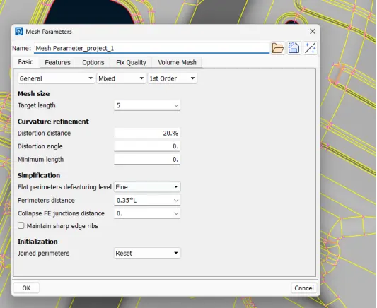
Target Element Length = 5 Units
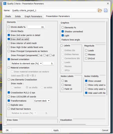
Next, mesh parameters are configured by going to Utilities>Mesh Parameters. The target length, minimum element length, and maximum element length are configured to 5, 2, & 7, respectively. All other parameters are kept as default for mixed and 1st order elements.
Quality criteria
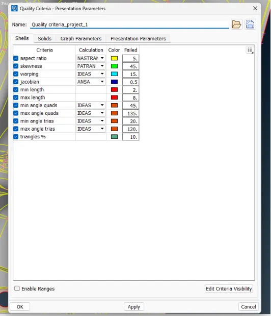
Mesh Parameters
15. Meshing
- Mesh all the mid-surfaces to qualify the quality criteria and confirm the same by viewing the model in hidden mode.
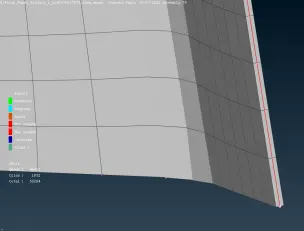
- For better mesh flow split the area and mesh.
Orange CON (edge) represents the joined macros (surfaces) and yellow CON is the new split done to divide the geometry into sections. Also, elements would fail for minimum length in the hemming region. So, for the hemming region, it is split into half along its length and the CON above and below are removed by joining the macros (surfaces) as shown below. - Next, meshing is done using the Mesh generation>Best tool. This tool generates the mesh using the best algorithm applicable. Then, the created mesh is refined using the Shell Mesh>Reconstruct It is ensured that there are no rotating quads. Also, trias are kept as low as possible.
16. While dealing with trias, the following things need to be ensured:
- No back-to-back trias touching each other
- No opposite trias
- No trias touching the edges
- No trias on a feature
- Low concentration of trias in a region
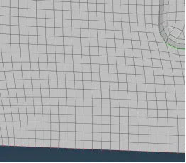
17. To deal with trias, the following tools are used:
- Grid>Paste, to paste the nodes and move tria backward
- Elements>Split, to split an element and move tria forward
- Elements>Swap, to move the tria left or right
- Elements>Join, to join two trias to make a quad
After modifying the mesh, Shell Mesh>Smooth tool is used to smoothen the flow of the mesh. Any elements failing for quality criteria are also fixed by either re-meshing or smoothing the elements.
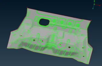
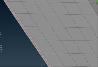
Final Mesh Model
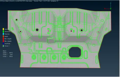
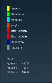
Thickness Applied assigning
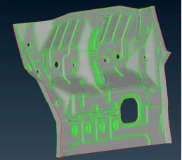
Thickness assigned Model
Result:
Quads = 48375 (96.3 %)
Trias = 1857 (3.69 %)
Total = 50232
Conclusion
- The geometry was cleaned, and the mid-surface was generated.
- The mid-surfaces meshed, and thickness was applied.