Project 1 Mechanical design of battery pack
Aim: Prepare a detailed battery pack drawing along with its enclosure. State your assumptions.
Battery pack capacity: 18 kWh
Cell: ANR26650M1-B.
========================================================================
ANR26650M1-B, 3.3 Volt, 2.5Ah Lithium Iron Phosphate (LiFePO4) Battery.
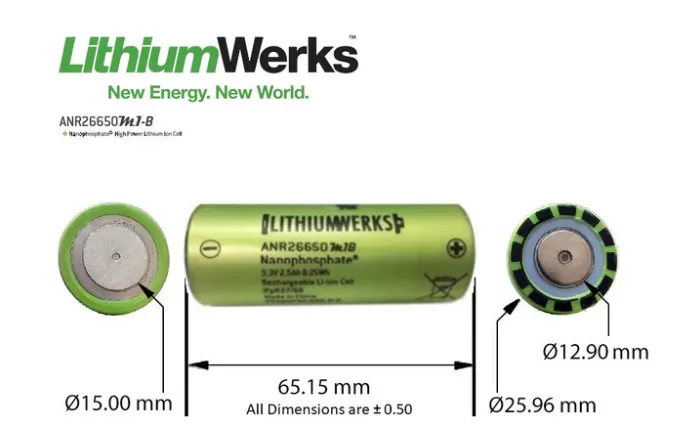
The ANR26650M1-B is the next generation of the pioneering 26650 cylindrical cell, now with greater power and energy density and lower impedance. This versatile lithium-ion cell is suitable for a wide variety of applications and system designs. Proven performance in the toughest conditions, combining durability, reliability, and safety, the ANR26650 cell offers an excellent combination of price performance.
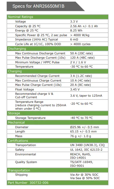
| Manufacturer: | LithiumWerks |
| Mfg PN: | 300732-006 |
| Chemistry: | Lithium Iron Phosphate (LiFePO4) |
| Voltage: | 3.3 Volts |
| Capacity @ 25°C: | 2.56 Ah |
| Energy @ 25°C: | 8.25 Wh |
| Energy @ 25°C: | 8.25 Wh |
| Specific Power: | >4000W/kg | (@ 25°C, 2-sec pulse) |
| Impedance: | >6mΩ | (1kHz AC) Typical) |
| Cycle Life: | > 4000 Cycles | (@ 1C/1C, 100% DOD) |
| Dimensions | |
| Height (max): | 65.15 (+/- 0.5 mm) |
| Diameter (max): | 25.96 (+/- 0.5mm) |
| Product Weight: | 76.0 (+/- 1.0 g) |
| Warranty: | DOA |
Cylindrical Cell Primary Applications
- Portable high-power devices
- Stationary battery backup systems
- Grid stabilization energy storage systems
- Commercial truck and bus hybrid electric vehicles (HEVs)
Nanophosphate® LiFePO4 Benefits
- Cycle Life at 1C/1C, 100% DOD, > 4000 cycles
- Safety: Excellent abuse tolerance and environmentally friendly
- Life: Excellent calendar life, 10X cycle life vs. conventional lithium-ion.
Lithium Werks’ 26650 cells are best for Power.Safety.Life.™ applications. They deliver very high power due to their use of patented Nanophosphate® battery technology. Based on lithium iron phosphate chemistry (LiFePO4), the cells are inherently safe over a wide range of temperatures and conditions. Whether the application requires outstanding cycle life or stable float reliability, the Lithium Werks’ 26650 cells are suitable for a wide variety of power, pulse, or stand-by applications.
Nanophosphate® battery technology offers thermal-stable chemistry, faster charging, consistent output, low capacity loss over time, and superior total cost of ownership (TCO). It provides the foundation for safe systems while meeting the most demanding customer requirements. Multiple layers of protection are employed at the chemistry, cell and system
level to achieve an energy storage solution with superior safety and abuse tolerance compared to metal oxide lithium-ion chemistries.
Data Sheet of battery cell ANR26650M1B
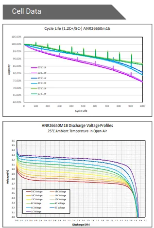
Battery Pack Use
When charging and discharging a battery pack, the current and voltage applied to any cell in the pack shall not be exceeded for the given conditions under which the cell are exposed. Appendix A details the limits the cells must be kept within for a given cell’s temperature and cell’s state of charge.
Charger Limits
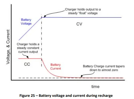
When charging or recharging Lithium Werk's cells in a battery pack, the charger should limit its output current and voltage to match that of the battery pack configuration. During recharge, the charger shall apply a constant current (CC) charge followed by a constant voltage (CV) charge. In addition, the charger shall cease charging when either:
• Any one cell in the series string, has exceeded its maximum recommended charge voltage, or
• The temperature measured in the pack has gone outside the recommended range for charging.
Lithium Werks recommends using cell balancing circuitry to achieve maximum life, reliability, and safety to
prevent an increasing spread between the highest and lowest battery states of charge. Refer to Cell Balancing on page
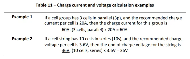
43 for more information. To determine the charge current for a parallel string of cells, multiply the number of parallel cells in the string by the recommended charge current for a single cell. Note that this calculation does not consider limitations imposed by any protection electronics or other features of the battery pack assembly.
Eq 5. Number of cells in parallel x Recommended Charge Current/cell = Charge Current/string
To determine the end-of-charge voltage for a series string of cells multiply the number of series elements in the string by the recommended charge voltage of a single cell.
Eq 6. Number of cells in series x Recommended Charge Voltage/cell = Charge Voltage/string.
Table 11 provides examples of two charge currents and voltage configurations
Once the end of charge voltage has been reached, apply a constant voltage hold at this voltage until the current decays to near-zero. This process charges the cells to 100% state of charge (SOC). Refer to Figure 25 for an illustration.
===========================================================================
Battery pack calculations
Battery pack capacity: 18 kWh.
Here we consider the pack voltage=300V.
Motor power rating required 55KW.
How do I convert kilowatt-hours to amp-hours?
Kilowatt-hours, abbreviated kWh or kW·h, are a measure of electrical energy. The energy equal to one kWh is equal to one kilowatt, or one thousand watts of power, consumed for one hour of time.
Converting from electrical energy to electrical charge can be done using the formula below. The voltage at which the charge is held must also be known.
Ah = kWh × 1,000/V
The electrical charge in amp-hours is equal to the energy in kilowatt-hours times 1,000, then divided by the voltage.
Ah=18x1000/300
Ah=60 .
Capacity of battery pack =60Ah.
Now as per the datasheet of cell ANR26650M1-B.
Voltage=3.3V.
Capacity=2.56.
Energy=8.25.
Hight=65.15mm.(0.06515m)
Diameter=25.96mm.(0.02596m)
cell weight=76 grams.(0.076Kg)
Specific power=4000w/kg
Voulue=pi*D^2*H/4=3.14*25.96^2*65.15=34466.2mm^3
no. of cells in series=300/3.3=90.90=90nos.
no of cells in parellel=60/2.56=23.43=24nos.
no of cells in battery pack=90x24=2160nos.
Actual pack voltage=91*3.3=297volt.
Actual capacity of battery pack=24*2.56=61.44.
Weight of the battery pack Approx=0.076*2160=164.16=164Kg
Now we consider the module of 15 series and 4 parallel cells 15S4P.
Module voltage=15*3.3=49.5volt
Module capacity=4*2.56=10.24Ah
So that we connect 6 modules in series and 6 modules in parallel.
Total no of modules=6*6=36nos
length of battery pack=90x25.96=2336.4/2=1168.2mm
width of battery pack=24x25.96=623.04mm
Hight of pack=65.15x2=130.3mm.
======================================================================
What is an Electric Vehicle’s Battery System?
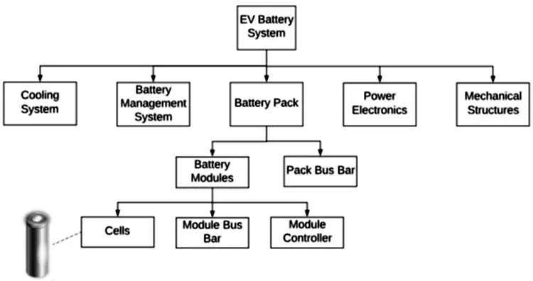
A battery system in an EV is the main energy storage system and the main constituents of it are cells. The design of an EV battery system requires knowledge and specialization in electrical, mechanical, and thermal engineering apart from material science and other domains. The flow diagram of an EV’s battery system is shown below:
Battery Pack
Highly modular battery pack with high efficiency, reliability, and safety features. As explained above, the battery pack is made up of up to 36 modules connected together in a series and parallel. The voltage of the battery pack is around 297 Volts and it is the single most heavy component.
The 2160 cells make the battery pack. But rather than arranging all the cells and making a single big battery, we multiple smaller batteries called the battery module to make the final battery pack. Each module has a 15S4P configuration, i.e. 15 cells are connected in series and 4 cells are connected in parallel that is 1 module consists of 50 cells.
We take the example of the Tesla car battery pack.
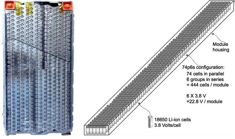
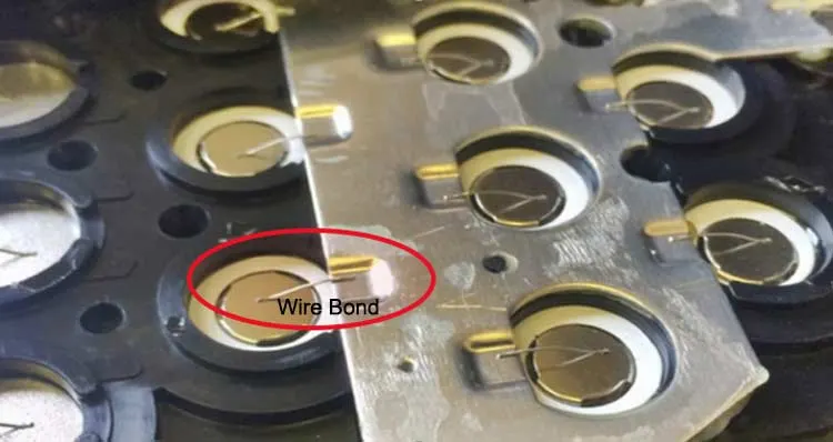
The left image shows the Tesla’s Model S battery module, while the right image shows how the battery is connected in a 6S 74P configuration. The pack has a configuration of 6S 74P and which makes the total number of cells as 444 cells. The total capacity of the battery module is 232 Ah and 5.3 kWh, to see how the series and parallel connection of the cell impacts its capacity and voltage check our previous article, designing a 12V battery pack. Tesla uses a wire bonding technique to connect each cell with the battery pack. The wire also acts as a safety fuse improving the safety of the overall system in case of a cell failure. The red circle in the below image shows how cells are connected using wire bonding.
Nickel strip for battery pack welding
Nickel strip is an important material for series and parallel connection in battery pack bilding. When we design the nickel strip, it will always be slotted at the spot welding position of the nickel strip, usually it is a small slot of 1*7mm, or cross slots with 1*7mm each slot. What is the effect of this slot?
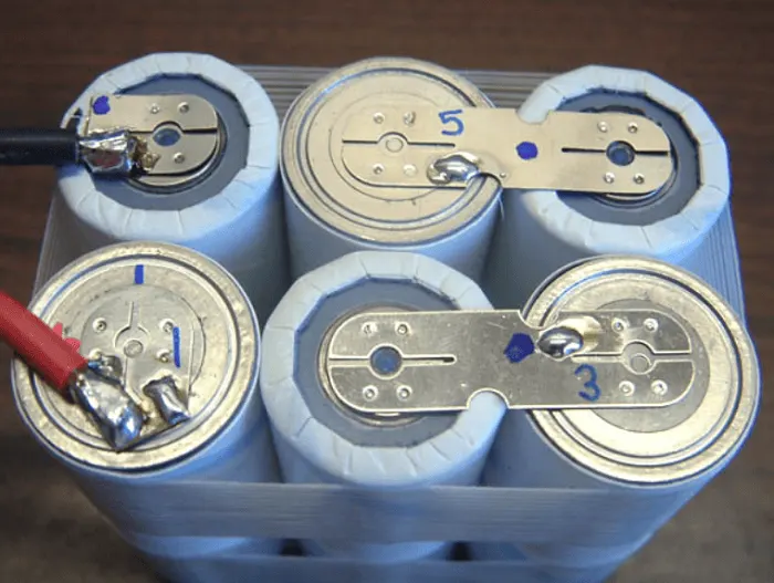
The function of the nickel strip slotting is to make the combination of the nickel strip and the battery core better, and the firmness of the spot-welding nickel strip will directly affect the performance of the battery pack. Therefore, it is necessary to do the test before production to ensure the firmness of the spot welding. The spot welding machine needs to be stopped every few hours, check the welding strength, and properly maintain the spot welding electrodes and the spot welding machine. Only continuous testing and maintenance can ensure the effect of nickel strip spot welding, ensure the quality of the battery pack PACK, and then ensure the performance of the battery pack.
Module’s Thermal Management
Li-ion cells are prone to heating under load and run the risk of a thermal runaway at high temperatures. The thermal runaway can increase the risk of fire hazards in a cell and subsequently initiate a chain reaction, thus, making the Li-ion battery pack and the EV unsafe to drive. The Thermal Management System is a very prominent safety feature that ensures that the temperature of the battery pack remains under a certain threshold by removing the heat from inside the battery pack. The below image shows the heat exchanger pipe which carries the cooling liquid inside the module.
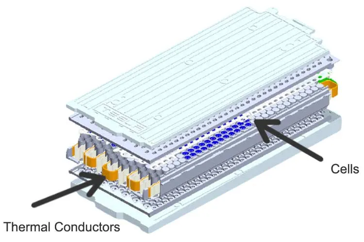
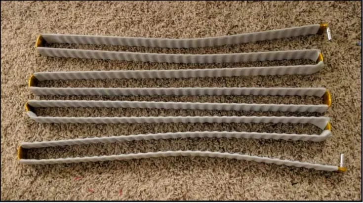
The cooling pipe is covered in thermally conductive and electrically insulative material which moderates the temperature inside the module while also isolating the cells from each other. At the bends, an orange insulating tape is used, this material is called Kapton tape and is used to improve the insulation. The coolant used in a Tesla’s battery pack is a solution of Water and glycol. The image below shows how the temperature of the solution increases as it flows through the battery pack.
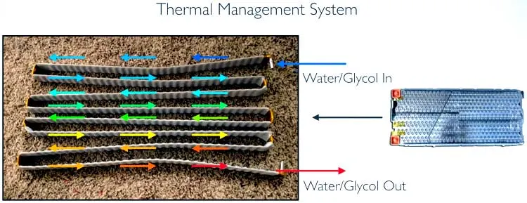
The image in the bottom published by AVL shows the temperature at different areas in a battery module after a high completion of a high-intensity test. The blue lines depict the coolant inlet while the red line depicts the coolant output. The maximum and minimum temperature of the cell in each module is also shown below.
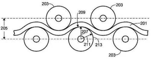
From the above image, it is clear that a low-temperature deviation was found between different modules. Maintaining a similar temperature is also important as it affects the internal resistance of cells and thus affecting the overall characteristics of the battery pack. The pipes containing the water-glycol solution has a patented wavy design, that increases the surface area as well as the packaging efficiency of the pack. The below image is taken from the patent document of the coolant pipe’s wavy design by Tesla.
Mechanical Structure of Tesla’s Battery Pack
The battery pack of Tesla model S also acts as a structural member and is placed at the underbelly of the car. It works as a foundation to the vehicle and provides rigidity and strength to the car and due to the positioning of such large weight in the lower part of the vehicle brings down the Center of Gravity of the car lower, thus increasing the balance and stability of the vehicle. The below image taken from the EV Tech Explained shows the structure of the empty battery pack.
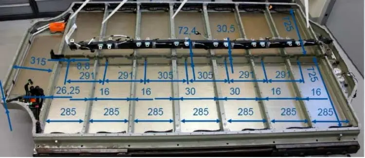
A total of 16 batteries can fit inside the base. Each niche accommodates a single battery module. The longitudinal members strengthen the chassis and provide resistance against longitudinal impact and side bending while the strength for the side is provided with the thick side members as they also provide protection against side impact. The internal members are used for making a grid for module placement but they also increase the strength and physical stiffness of the base while also isolating modules from each other in case of fires. The below image shows the placement of all 16 modules. On the right, the graphical illustration shows how the modules are connected with each other.
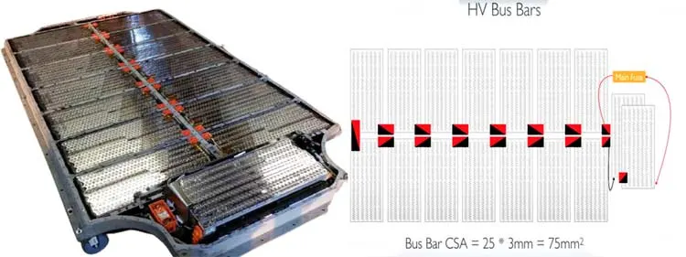
The HV bus bar is connected in the above orientation. The red points depict a positive connection while the black depicts the negative side of the connection in the battery pack. Busbars used in the battery pack are thick copper-coated tin plates.
BMS used in Tesla Model-S
Battery Management Systems (BMS) is the most important component in a battery pack essential for the battery pack’s safety. The BMS is based around a Texas Instruments IC capable of monitoring overcharge, over-discharge, SOC, SOD, temperature, etc of a battery pack. We have previously covered the importance of BMS. The picture of the Tesla Model-S BMS is shown below.
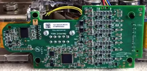
The BMS used by Tesla in Model-S is based around Texas Instrument’s bq76PL536A-Q1 3-to-6 Series -Cell Lithium-Ion Battery Monitor and Secondary Protection. The BMS is integrated into every module and monitors the battery life, temperature, and charge-discharge cycle of cells. It is a stackable Battery Monitoring System and uses a High-Speed Serial Peripheral Interface (SPI) for Data Communications. The image below shows a simplified system connection of the BMS.
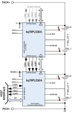
The BMS can communicate with each other using SPI communication. All the module’s BMS act as a slave BMS and communicate with a master BMS via an isolation barrier, the master BMS communicates with the ECU and charger and controls the main contactors. The BMS is placed on a side of every battery module. The cell voltage measurement is performed using wires welded to the connecting plates of the parallel connections. Not much data is available about the BMS module used in Tesla Model S, hence few calculated assumptions are taken about the BMS technology.
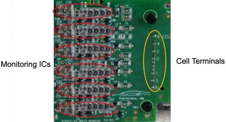
The red encircled area in the above picture of BMS shows that the BMS contains 6 monitoring ICs for each series connection in the module. The yellow encircled area shows the terminals where the connection from the 6 cells will be connected. The IC by TI used in the BMS can be daisy-chained in order to need only one communication connection to the system. And probably the master BMS used is developed by BOSCH, the whole system utilizes CAN bus communication to communicate with the vehicle’s central computer. If you have any extra information kindly feel free to post it so that we can update it.
Conclusion
- Calculate the battery pack parameters as per the datasheet of ANR26650M1-B.
- We assume a battery pack voltage of 300V and a module of 15 cells in series and 4 cells in parallel cells 15S4P.
- Cells connected with the nickel strip and cell and strip spot welded.