Project 1 Mechanical design of battery pack
Aim:
To Prepare a detailed battery pack drawing along with its enclosure
Given Data:
Battery pack capacity: 18 kWh
Cell: ANR26650M1-B
Solution:
The Battery needs to be designed which we need to consider from the bottom level of selection of cells to the end of the battery, so the various steps needs to followed in order to design a battery which are mentioned below.
1. Selection of the cells
2. Determining the total number of cells required
3. Connection Required for connecting the cells
4. Selection of BMS
5. Dimensions
6. Final Assembly
By following this steps we can easily design the battery pack , the above steps are mentioned in detail below.
1.Selection of Cells
We no need to worry about the chemistry of cells since the cell is already been decided which is LifePo4, the detailed explanation is given below.
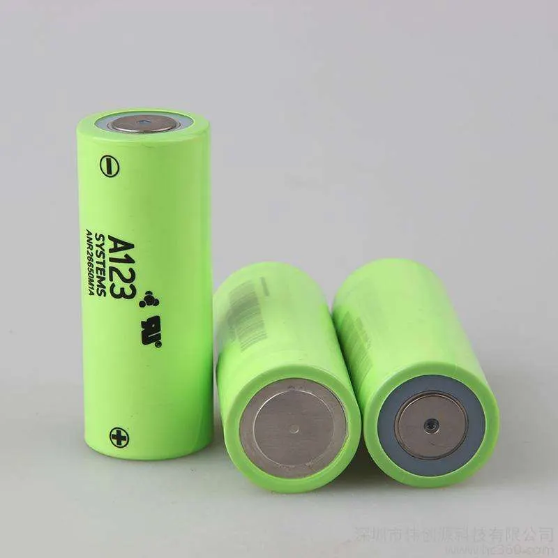
A123 Systems ANR26650M1-B 2500mAh 3.3V LiFePO4 nanophosphate rechargeable Lithium ion battery
Nanophosphate® ANR26650M1-B:
A123 Systems ANR26650M1-B 2500mAh 3.3V LiFePO4 nanophosphate rechargeable Lithium ion battery is the next generation of A123 Systems pioneering 26650 cylindrical cell, now with greater power and energy density and lower impedance. This versatile lithium ion cell is suitable for a wide variety of applications and system designs. Proven performance in the toughest conditions, combining durability, reliability, and safety, the ANR26650 cell offers an excellent combination of price-performance.
Cylindrical Cell Primary Applications:
- Portable high power devices
- Stationary battery backup systems
- Grid stabilisation energy storage systems
- Commercial truck and bus hybrid electric vehicles (HEVs)
Lithium Ion Cell Benefits:
- Power: Over 2,600 W/kg and 5,800 W/L
- Safety: Excellent abuse tolerance and environmentally friendly
- Life: Excellent calendar life, 10X cycle life vs. conventional lithium ion
Go to downloads to download A123 systems official data sheets.
A123 Systems ANR26650M1-B 2500mAh 3.3V LiFePO4 nanophosphate rechargeable Lithium ion battery
Discharge Curve
Battery Specifications:
- Model: ANR26650M1-B
- Positive terminal style: Flat-top
- Protected (PCB): No
- Manufacturer: A123 Systems
- Country of Origin: USA and China
- Chemistry: LFP (LiFePO4)
- Max. continuous discharge current: 70A
- Maximum pulse discharge: 120A
- HPPC 10 sec Discharge pulse power: 200W
- Rated capacity (minimum): 2500 mAh
- Nominal capacity: 2500 mAh
- Nominal voltage: 3.3 V
- Discharge end voltage: 2 V
- Charging voltage: 3.6 +/- 0.03 V
- Standard charging current: 2.5A (1C)
- Fast charging current: 10A (10C)
- Operating temp: -30 degrees C to +60 degrees C
- Dimensions: 65mm (L) x 26mm (D)
2. Determining the Total number of cells Required
In order to make a battery we need a various number in cells in combination which can fullfill the conditon of the required power and voltage required, so we need to following calculation which make us know the total numbers of cells required.
Number of cells in series
The cells are connected in series in order to match the required voltage, the series connection are nothing but to connect the oppsite terminals of each cell with other cell
Calculations:
lets assume the Voltage as 400 V
Therefore total number of cells in series = Total voltage / nominal voltage of each cell
= 400 V / 3.3 V
=121.12 = 122 Nos
Number of cells in Parallel
The cells in parallel is connected in order to match the required capacity, the parallel connection are nothing but connecting positive of each cell with the othere cell positive.
Calculations:
Capacity = Energy / Total voltage
=18000 / 400
= 45 Ah
Therefore total number of cells in parallel= capacity / capacit of each cell
= 45 / 2.5
= 18 Nos
Total number of cells = Total cells in series * Total cells in parallel
= 122 * 18
= 2196 nos
Finally is the battery is 122S18P which we can be arrange as per the our requirement , wheather it may be the module or the normal connections , But in safety we can go for the Modules which may be easy for the safety requirements. The image shows the 7 different modules which make a pack of battery .
3. Connection required for connecting the cells.
Now we have the total number of cells required to fulfill the requirements, but we need to give the connections , there are various techiniques in order to connect the cells but we can go for spot weilding
Spot welding (or resistance spot welding) is a type of electric resistance welding used to weld various sheet metal products, through a process in which contacting metal surface points are joined by the heat obtained from resistance to electric current.
The process uses two shaped copper alloy electrodes to concentrate welding current into a small "spot" and to simultaneously clamp the sheets together. Work-pieces are held together under pressure exerted by electrodes. Typically the sheets are in the 0.5 to 3 mm (0.020 to 0.118 in) thickness range. Forcing a large current through the spot will melt the metal and form the weld. The attractive feature of spot welding is that a large amount of energy can be delivered to the spot in a very short time (approximately 10–100 milliseconds). This permits the welding to occur without excessive heating of the remainder of the sheet.
The amount of heat (energy) delivered to the spot is determined by the resistance between the electrodes and the magnitude and duration of the current. The amount of energy is chosen to match the sheet's material properties, its thickness, and type of electrodes. Applying too little energy will not melt the metal or will make a poor weld. Applying too much energy will melt too much metal, eject molten material, and make a hole rather than a weld. Another feature of spot welding is that the energy delivered to the spot can be controlled to produce reliable welds
4. Battery Management System
A battery management system (BMS) is any electronic system that manages a rechargeable battery (cell or battery pack), such as by protecting the battery from operating outside its safe operating area, monitoring its state, calculating secondary data, reporting that data, controlling its environment, authenticating it and / or balancing it.
A battery pack built together with a battery management system with an external communication data bus is a smart battery pack. A smart battery pack must be charged by a smart battery charger.
Functions[edit]
Monitor[edit]
A BMS may monitor the state of the battery as represented by various items, such as:
- Voltage: total voltage, voltages of individual cells, or voltage of periodic taps
- Temperature: average temperature, coolant intake temperature, coolant output temperature, or temperatures of individual cells
- Coolant flow: for liquid cooled batteries
- Current: current in or out of the battery
- Health of individual cells
- State of balance of cells
5. Dimensions:
Total length of the battery = Dia of each cells * Total cells in series* Clearence between each cells( assume as 1.5)
= 26*122*1.5
=4758mm
Total width of the battery = Dia of each cell * total cells in parallel * clearence between each cells
= 26*18*1.5
= 702mm
Total height of the battery = Length of each battery * Clearence for the connections
= 65*3
= 195mm
6. Final Assembly
The final assembly is done by connecting all the following setups and also we need to plan the following conditon before the final assembly.
- To make sure the atmospheric air is used to flow all the battery
- To make sure no dust is coming inside the enclosure
- To make sure that there is no mechanical vibrations in the battery which may cause the connections to come out
- To make sure that there in no way to the water to get inside.