Project 1 Mechanical design of battery pack
Objective:
Battery pack capacity: 18 kWh
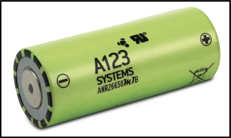
Cell: ANR26650M1-B
Prepare a detailed battery pack drawing along with its enclosure. State your assumptions.
Theory:
Li-ion cell(ANR26650M1-B):
A123’s high-performance Nanophosphate® lithium iron phosphate (LiFePO4) battery technology delivers high power and energy density combined with excellent safety performance and extensive life cycling in a lighter weight, more compact package.
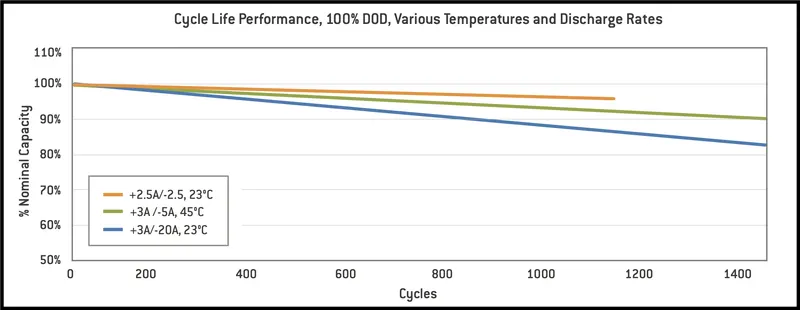
For outstanding cycle life, stable float reliability this cells are suitable for a wide variety of power, pulse and stand by applications.
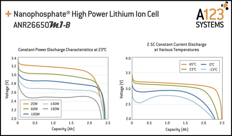
Nanophosphate battery technology offers thermal stable chemistry, fast charging, consistent output, low capacity loss over time.
It provides extremely safe conditions for while meeting most demanding customers requirements.Multiple layers of protections are employed on chemistry, cell and system level to achieve an energy storage solution with superior safety.Our cells have low capacity loss and impedance growth over time as well as high usable energy over a wide state of charge (SOC) range, allowing our systems to meet end-of-life power and energy requirements with minimal pack oversizing.
Applications:
COMMERCIAL SOLUTIONS
Advanced lead acid replacement batteries for:
+ Datacenter UPS
+ Telecom backup
+ITbackup
+ Autonomously guided vehicles (AGVs)
+ Industrial robotics and material handling equipment + Medical devices
GOVERNMENT SOLUTIONS
+ Military vehicles
+ Military power grids + Soldier power
+ Directed energy
GRID SOLUTIONS
+ Frequency regulation
+ Renewables integration
+ Reserve capacity
+ Transmission and distribution
TRANSPORTATION SOLUTIONS
Hybrid, plug-in hybrid and electric vehicle battery systems for:
+ Commercial vehicles
+ Off-highway vehicles
+ Passenger vehicles
Assumptions:
We are assuming the overall voltage required to operate the motor and other accessories of electric vehicle as 72V.
So we have construct the battery pack of 18KWh for a 72 V input voltage motor. Vehicle Range =150 KM (assumed)
Construction of battery pack:
To construct a battery pack initially we have to estimate the voltage requirement of the overall load of vehicle.
We had assumed as 72V as mentioned above.
Then the battery modules should be created in such a way that the overall voltage is matched with the load requirement voltage.
The modules can be created in series/parallel connections of individual cells.Then every modules should be connected in series/parallel to construct final battery pack.
In series connection-Voltage added and Current remains same.
In Parallel connection-Voltage remains same and Current gets added.
Basically, the value of the volume of the cell is used to find out the total volume of the battery pack.
- Single Cell Energy (Wh)
= Cell Capacity (Ah) x Cell Voltage (V)
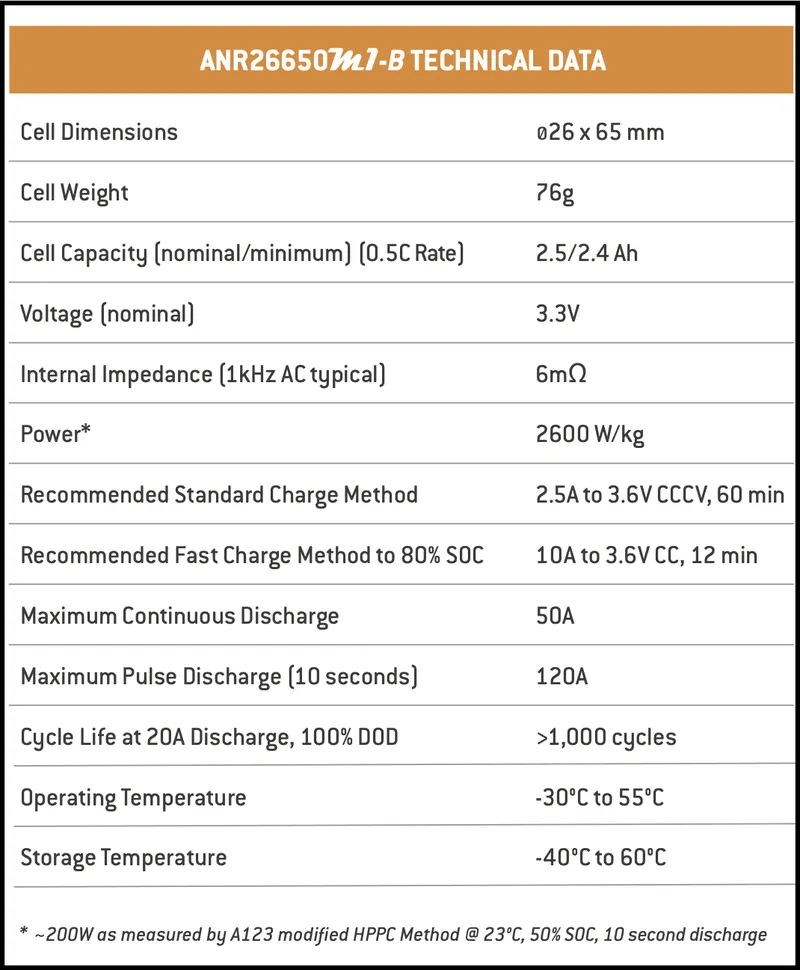
= 2.5 x 3.3
= 8.25 Wh
For 18KWh battery pack we need approximately(18000/8.25=2182 cells).
We have to create a single module to produce 72 V for our load requirement.
So to obtain 72 V output ,cells are connected in series where voltage become added and current remains same.
Nominal Voltage of Pack = Single Cell Voltage * No. Of Cells in series
72=3.3*No. Of Cells
No. Of Cells in series = 72/3.3 = 21.818 ≈ 22 Cells in Series.
Thus single module gives as 72V from 22 cells but energy of one module is not enough to run the vehicle as motor power rating is higher.The energy generated from
single module is (22*8.25Wh=181.5 Wh).
Now we have to find how many similar modules should be connected in parallel to achieve 18KWh battery pack.
Power = Pack Nominal Voltage * Nominal Current of Pack
18 KWh = 72 * Nominal Current of Pack
18000 Wh = 72 * Nominal Current of Pack
Nominal Current of Pack = 18000/72 = 250 A
Nominal Current of Pack = Single Cell Nominal Current * No. Of Cells in Parallel
No. Of Cells in Parallel = Nominal Current of Pack/Single Cell Nominal Current
No. Of Cells in Parallel=250/2.5 = 100
This can be calculated as (18000Wh/181.5Wh =99.17≈ 100 cells),which gives as nearly 100 similar modules should be connected in parallel to achieve 18KWh battery pack.
Thus the battery model is said to be 22S100P configuration(22 series and 100 parallel connections),which gives us (22*100 =2200 cells).From this we have created overall capacity of battery pack as (2200*8.25Wh=18150 Wh) which is slightly higher than 18KWh.
The overall Capacity(Ah) of battery pack is given as (2.5Ah * 100 = 250Ah).
Which means it provided 250 A of current continuously for one hour to full discharge.
Thus 18 modules should be arranged in a way as battery pack to fit in an EV chassis.
Now,
We will calculate per km average energy = 18150 / 250
= 72.6 Wh/km
Enclosure construction:
Mechanical
Diameter: Ø26.0
Length: 65.0
Mass: 76 g
To find overall enclosure volume we have to find the volume of single module volume consist of 22 cells in series connection and multiplied with 100 parallel connected module volume.
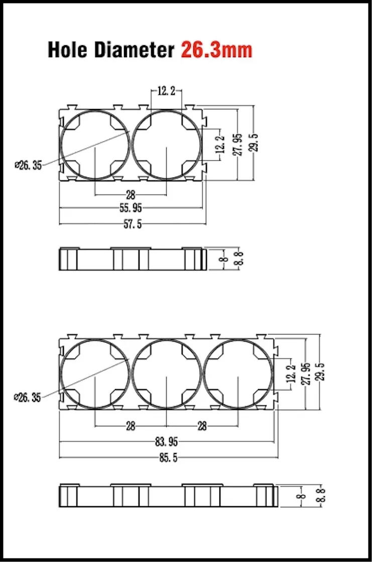
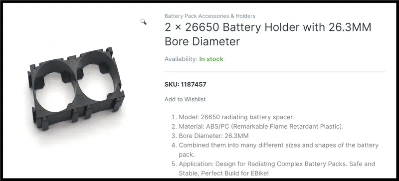
Single module,
Let as assume 22 cells(single module) are divided into 2 modules of 11+11 cells.
The length of the module
(L1)=3 Cell holding 3 Holders for 9 cells + 2 Cell holding 1 Holder for 2 cells+clearance
=(83.95*3)+(55.95)+2
= 251.85 + 55.95+2= 309.8 mm ≈ 310 mm
100 cells parallel connected module volume.
The breadth of the module(B)=(width of holder + side clearance)
=27.95*100+2 =2797mm ≈ 2800mm
Cell holder and wire dimensions data
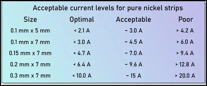
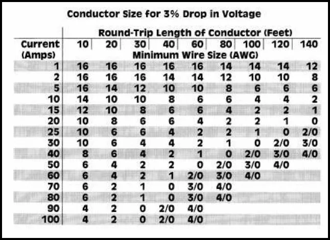
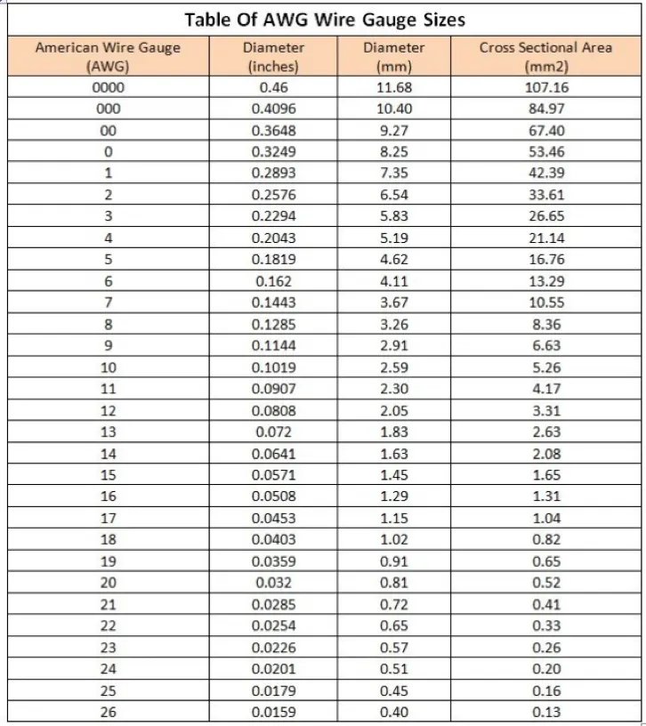
Height of the module (H)=Height of cell + connecting strip thickness + (Holder thickness *2 for top and bottom) + wire size + clearances
=65+0.1+(8*2)+1.29+1 =83.39 mm.≈ 84 mm
Sizes for 1 module = L1 * B * H
= 310 * 2800 * 84
=0.31*2.8*0.084=0.072912 M^3
2 modules =0.072912 *2 = 0.145824 M^3
Total Size of Module =0.145824 M^3
- Battery pack Cell volume,
One cell radius = 26/2 = 13 mm = 0.013 m
one cell length= 65 mm = 0.065 m
one cell volume = π*r^2*h
= 3.1415 * (0.013)^2 * 0.065 = 0.0000345 m^3
= 0.0345 Ltr
Total battery pack volume = 2200*0.0345 = 75.99 Ltr
- Battery pack cell mass,
One cell mass= 76 g
Battery pack mass= 76 * 2200 = 167200 g = 167.2 Kg.
- Energy Density of Battery Pack,
Battery pack mass= 167.2 Kg
Energy of battery pack= 18 kWh= 18000 watt-hour
Energy density= (18000/167.2) = 107.65 Wh/Kg
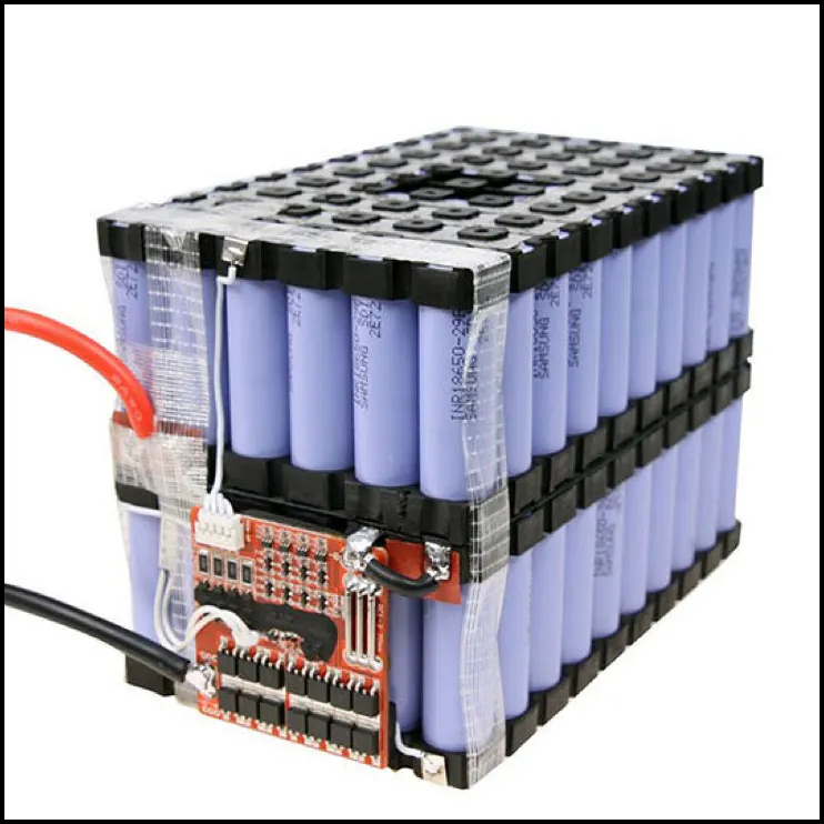
Battery pack constructions consist of three major levels of processings namely cell level, module level, pack level constructions.
The electrodes are combined with electrolyte to various cell models as cylindrical, prismatic, pouch type cells.
After case sealing cells are combined to form module level construction.Finally these modules are combined to form pack level constructions.
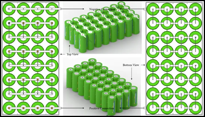
BATTERY HOLDER, SPACER For CELL CYLINDRICAL LI-ION
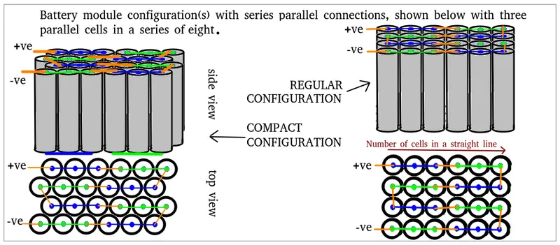
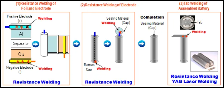
Cell connecting / Joining process
(1)Resistance Welding of Foil and Electrode
- Positive electrode: Al foil and Al electrode tab are resistance welded.
- Negative electrode: Ni electrode tab is resistance welded to Cu foil.
- Applicable machine models: Inverter Type Welding Power Supply NRW-IN400P, Capacitor (DC) Type Welding Power Supply NRW-DC150
(2)Resistance Welding of Electrode
- Positive electrode: Al electrode is resistance welded to Al bottom cap.
- Negative electrode: Ni electrode is resistance welded to the bottom of Fe (Ni plated) can.
- Applicable machine models: Inverter Type Welding Power Supply NRW-IN400P, Capacitor (DC) Type Welding Power Supply NRW-DC150
(3)Tab Welding of Assembled Battery
- Multiple cylinder-shaped batteries are connected by laser welding or resistance welding using the Ni tabs.
- Applicable machine models: YAG Laser Welder LW-Y20, LW-Y50, Inverter Type Welding Power Supply NRW-IN400P
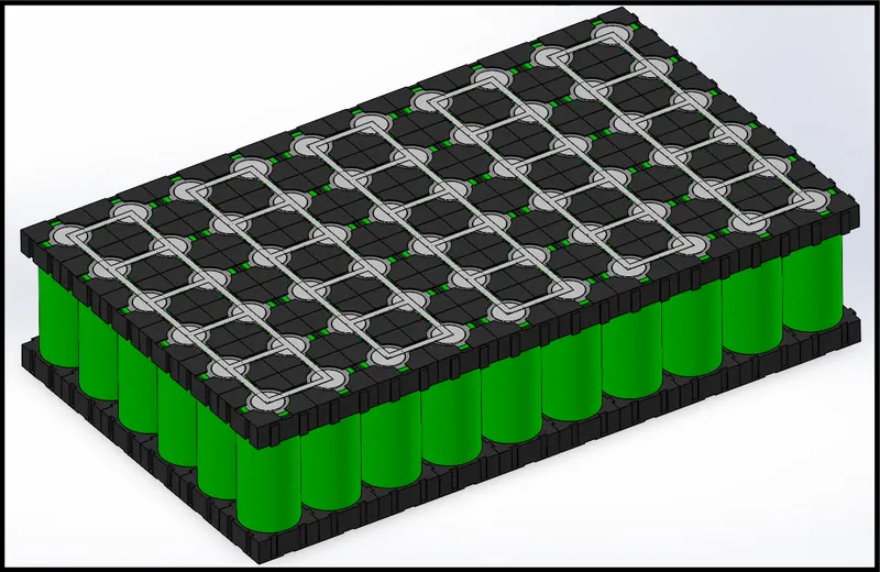
Add cell holders on the upper side of cells and also add nickel strips for series and parallel connections
BMS
Hence a BMS is a highly crucial device to ensure the safety of the battery and user.
A BMS is an electronic board consisting of a variety of components and circuitry. After detecting a problem in operational parameters (voltage, temperature etc.) BMS triggers input to the alarm system followed by disconnecting the battery pack from the load or charger.
Block Diagram of BMS :-
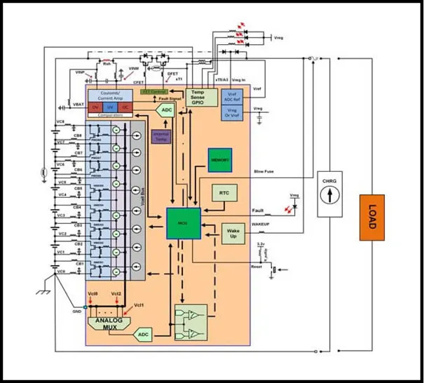
There are four main functional blocks,
- Cut-off FETs
- Fuel Gauge Monitor
- Cell voltage monitor
- Temperature Monitor
- Cut-off FETs
A FET-driver acts as isolation between the battery and the charger. It is used to connect the high-side and low-side of the battery pack.
High-side – Activates N-MOSFET using the charge pump driver
Low-side – Activates N-MOSFET without charge pump driver
This integrated Cut-off FETs reduce the overall cost of the BMS. It is also eliminating the use of high voltage devices that could consume a large die area. (The MOSFET is the most common type of transistor today. Their primary use is to control conductivity, or how much electricity can flow, between its source and drain terminals based on the amount of voltage applied to its gate terminal.)
- Fuel Gauge Monitor
This helps in keeping track of the charge entering and exiting the battery pack. The charge flowing is calculated by multiplying current and time.
Although several methods are used to measure the current flow, the most efficient and cost-effective solution is to measure the voltage of sense resistor using a 16-bit ADC with low offset and high common-mode rating.
Higher ADC is beneficial to obtain an extensive dynamic range at more speed.
- Cell Voltage Sensors
Cell voltage monitoring can be called as a standard function of the Battery Management System. It is useful in determining the health of the battery.
All cells in a battery should operate at standard voltage levels during charging and discharging for safety and improving the lifecycle.
- Temperature Monitoring
As technology is evolving, batteries are made to supply high currents in the meantime keeping the voltage constant.
Since a high current flow through batteries can cause sudden temperature rise and force them to explode accidentally. It needs to be avoided. For this reason, the BMS continuously monitor the temperature of the battery and regulate it to the rated value.
This feature is handy because if the temperature rises above the rated value, it will inform you to start/stop charging or discharging.
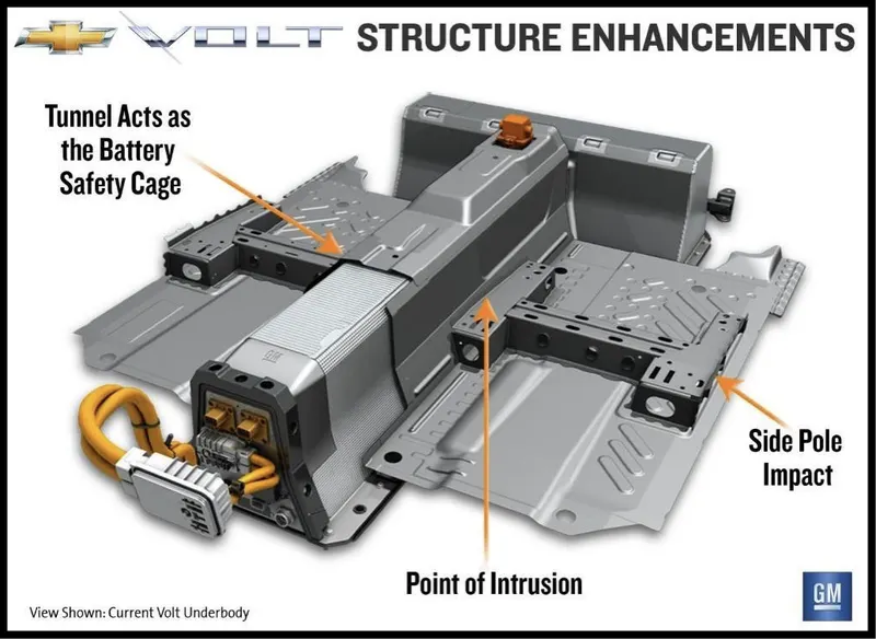
Crash protection
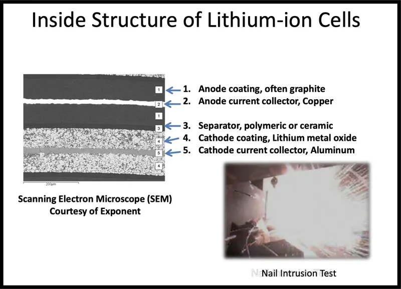
Problem: Internal Short of Batteries During Vehicle Crash
- How much deformation/force a cell can tolerate before reaching internal short circuit?
- Vehicle crashes are inevitable. Often battery packs are also damaged in case of a crash!
- How to design batteries, packs, and vehicle structure to minimise risk of thermal runaway in case of a crash?
Finite Element Modeling as a Tool for Design and Optimization
- Finite element model of batteries for: – Identify best electrode/separator components – Choice of cell shell casing (material & geometry) – Choice of center core (material & geometry) – Design of BIW, pack housing and connections.
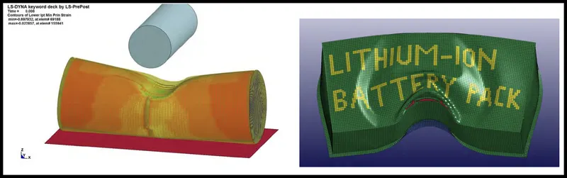
Finite Element Models
- A model of cell is developed by discretizing geometry into small elements • Boundary conditions are applied
- Loading conditions are applied
- Material propertied are defined
- A software (here: LS Dyna) used to solve partial differential equations of the boundary value problem
- Here for the Battery Model, two parts are defined: – Solid element for jellyrolls – Shell element for cell casing
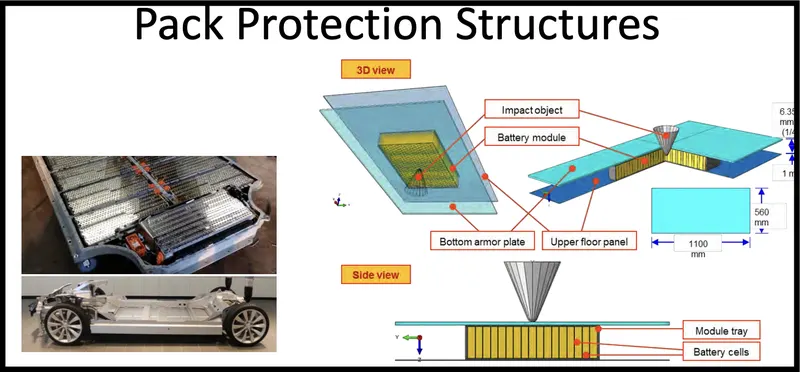
Battery crash response is an important part of battery design for an electric vehicle
- An experimental program using a combination of compression and tensile loading on battery cells and its layered components can be used to characterize material properties of the cell
- Finite element modeling is an effective tool to predict deformation of a battery cell under crash loading
- Finite element modeling is used to predict effect of strength of each layer on average properties of a cell
- Effective design of protective plate can reduce damage to battery cells
Thermal Design:
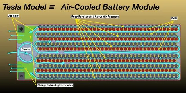
Thermal management is a major issue in high power designs, particularly for automotive applications. See details in the Thermal Management section. As part of the battery system, it may be necessary to provide air or water cooling ducts, pumps or fans and heat exchangers for high temperature working or heaters for operating in low temperature environments. The layout of the cells should be conducive to managing heat flows within the pack.
Passively air-cooled batteries like those in early Nissan LEAF cars have demonstrated unacceptable hot weather performance, even when using a lower energy, thermally tolerant battery chemistry. Clearly, Tesla will need robust temperature control for Model 3 batteries as they have for the batteries in Models S/X.
Cooling (and heating) the battery cells by circulating air within the sealed battery pack through a heat exchanger connected to the car's HVAC system, and then over the cells can achieve the same or even better thermal control as Tesla's current liquid cooling scheme. The difficulty is that quite large volumes of air must be moved past the cells, and that requires large cooling passages and much larger battery modules to hold a given number of cells.
Battery Packing:
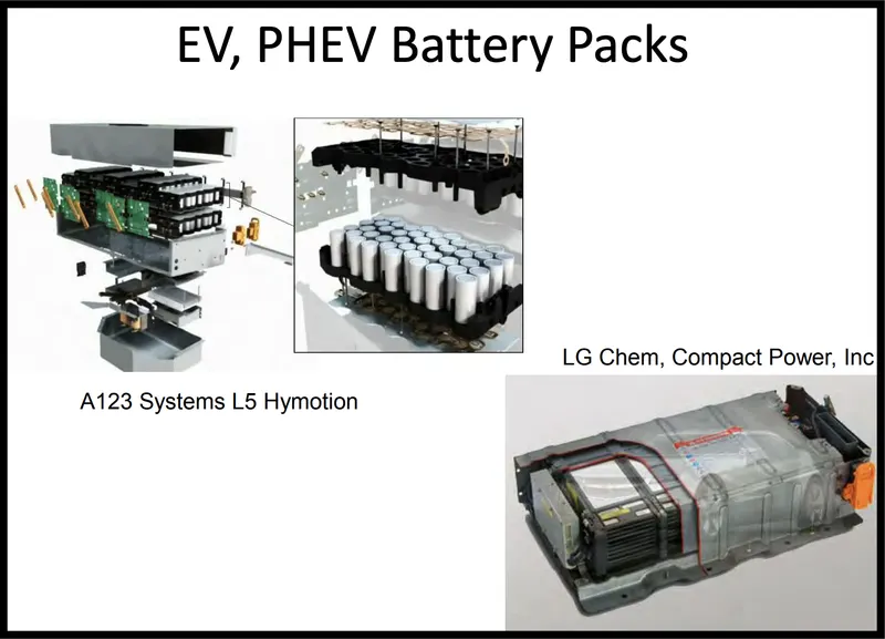
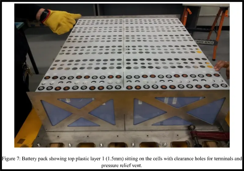
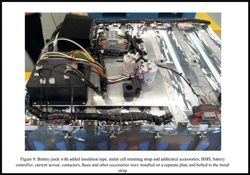
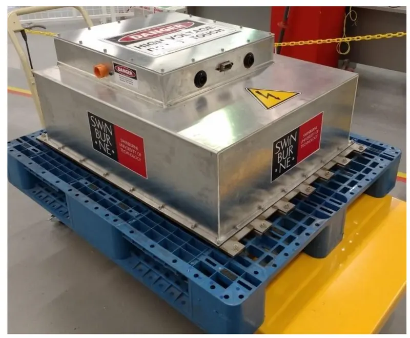
The battery casing has to provide the mechanical and electrical interfaces to the product it is designed to power as well as to contain all the components outlined above. This is how the battery pack will be which is manufactured by the companies and employed in an Electric Vehicle.
Conclusion
Mechanical design elements affecting safety and reliability of EV battery packaging are discussed. Forces like mechanical vibration, impact energy and ambient temperature variations interact with the battery pack through different interfaces. These interactions need to be controlled for safe and reliable operation of battery pack. Restricting battery cell movement is found to be one of the successful strategies to achieve a higher degree of protection against all of them and mechanisms that can be used for this purpose are presented. Other mechanical design solutions to increase crashworthiness and vibration isolation of the EV battery pack are discussed.
References:
https://datasheetspdf.com/pdf/1424845/A123Systems/ANR26650M1-B/1
https://robu.in/product/2-x-26650-battery-holder-with-26-3mm-bore-diameter/
https://evbatterysolutions.com/#
https://in.mathworks.com/help/sps/ug/lithium-pack-cell-balancing.html
https://www.avio.co.jp/english/products/assem/application/solution/cylindrical-lithium/