Project 1 Mechanical design of battery pack
AIM :-
To develop a battery pack of 18KW using ANR26650M1-B cells along with their mechanical design.
THEORY :-
BATTERY PACK:
A battery pack is a set of any number of (preferably) identical batteries or individual battery cells. They may be configured in a series, parallel or a mixture of both to deliver the desired voltage, capacity, or power density. The term battery pack is often used in reference to cordless tools, radio-controlled hobby toys, and battery electric vehicles. Components of battery packs include the individual batteries or cells, and the interconnects which provide electrical conductivity between them. Rechargeable battery packs often contain a temperature sensor, which the battery charger uses to detect the end of charging. Interconnects are also found in batteries as they are the part which connects each cell, though batteries are most often only arranged in series strings. When a pack contains groups of cells in parallel there are differing wiring configurations which take into consideration the electrical balance of the circuit. Battery regulators are sometimes used to keep the voltage of each individual cell below its maximum value during charging so as to allow the weaker batteries to become fully charged, bringing the whole pack back into balance. Active balancing can also be performed by battery balancer devices which can shuttle energy from strong cells to weaker ones in real time for better balance. A well-balanced pack lasts longer and delivers better performance. As we know that the electric vehicle market is gradually increasing. With the growth of an electric vehicle, the growth and interest in Lithium-ion cell are also increasing. The energy source for an electric vehicle is stored in cylindrical cells. Lithium-ion cells are capable of delivering very high power. Lithium-ion cells are used in aerospace, automotive electric vehicle, mobile devices, medical devices and other electronic devices which is based on these cells. The battery pack is installed in lower-floor of the electric vehicle so that weight may distribute equally and also the centre of gravity also maintain properly.
The high voltage battery pack is one of the most important components of any electric vehicle. The traction battery of an electric vehicle must achieve the following thing:
- Provide maximum traction motor torque
- Vehicle range in sense of kilometre
- To achieve the proper life cycle of battery
The battery pack of an electric vehicle is generally having a series or parallel combination. Large battery pack have multiple cell modules, in which many numbers of cells are kept together to build a large battery pack. Basically, a series connection is used to compound the voltage whereas the parallel connection is for compound current capacity. A battery cell consists of five major components that are electrodes – anode and cathode, separators, terminals, electrolyte and enclosure.
Mechanical design of battery pack :
Safety and reliability are two major things for large battery packs. While mechanical designing of large battery pack we should follow some technical criteria so, that the battery may not fail.
- Mechanical vibration should decrease
- Controlling on high impact force
- Better thermal runway for cooling
- Serviceability and recyclability
For the designing of 18 kWh battery pack here, we use a base model of ANR26650M1B Lithium-Ion Cell. ANR26650M1B cell is consist of lithium iron phosphate chemistry (LiFePO4) and it is best for use in a wide range of temperatures and conditions. The ANR26650M1B Lithium Ion cell may achieve the following features:
- Stable chemistry
- Faster charging
- Consistent output
- Excellent cycle life
- Superior cost performance
The provided battery cell type is ANR26650M1-B and its datasheet is used to get all the required information about it. After that, we will figure out how many cells do we require to achieve the said 18 kWh capacity and also the configuration of their connection. In the end, a detailed battery drawing along with its enclosure is given to understand the working of it more deeply.
CALCULATIONS :-
To make the battery pack, we have to first finalize the nominal voltage and capacity of the pack. Either it will be in term of Volt, mAh/ Ah or Wh.
Total required Battery pack capacity is 18 kWh = 18000 wh
The individual Cell: ANR26650M1-B has
Nominal voltage = 3.3 V
Current Capacity = 2.5 Ah
So, let us assume that for 18 kwh battery pack we need supply voltage of 72 V.
Total voltage = single cell voltage*cells in series
72 V = 3.3 * Cell in series
Cell in series = 72/3.3 = 21.81= 22
Now, as we know that battery pack capacity (Wh) = Total current * Total voltage --------(1)
Consider Crate = 1C
Cells in parallel = Total current/cell current
Total current = Cell current*Cells in parallel -------(2)
subsituting (2) in (1)
battery pack capacity (Wh) = ( Cell current*Cells in parallel )* Total voltage
18000 = (2.5* cell in parallel) *72
Cell in Parallel = 18000/ (2.5*72) = 100
Total number of cells = cells in series*cells in parallel
= 22*100 = 2200
So, the battery can be expressed as 22S103P
Step by step method to design a battery pack
1. Choosing the correct cell
A correct cell must be chosen for a particular battery pack depending on its application for their proper operation. The cells must have a well-documented performance characteristics and excellent quality control. The reputed brands are generally costly, but have a long life and in the long run are the best option for the designing of battery packs.
Nano phosphate High Power Lithium Ion Cell ANR26650M1-B cell is taken.
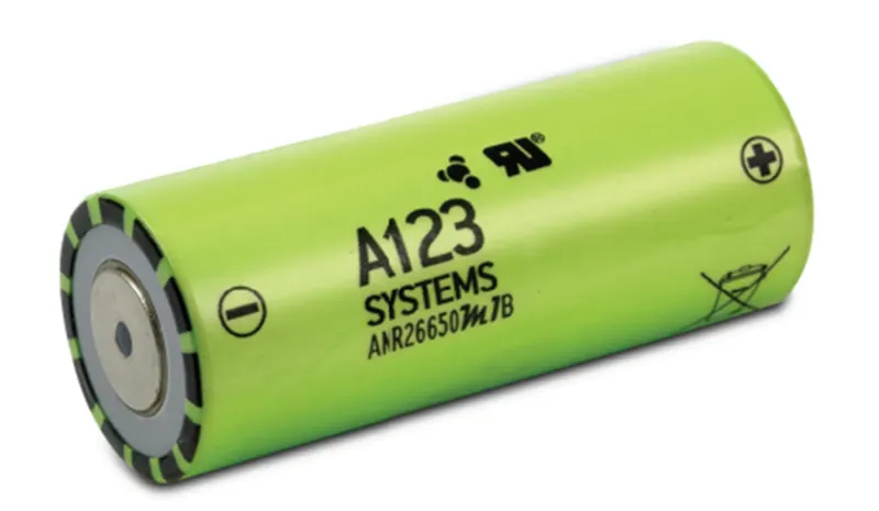
Fig 1.2
2. Check the cell voltage
Before connecting the cells in parallel, first check the individual cell voltages. For paralleling the cells, the voltage of each cell should be near to each other, otherwise a high amount of current will flow from the cell with higher voltage to the cell with lower voltage. This can damage the cells and even result in fire on rare occasions.
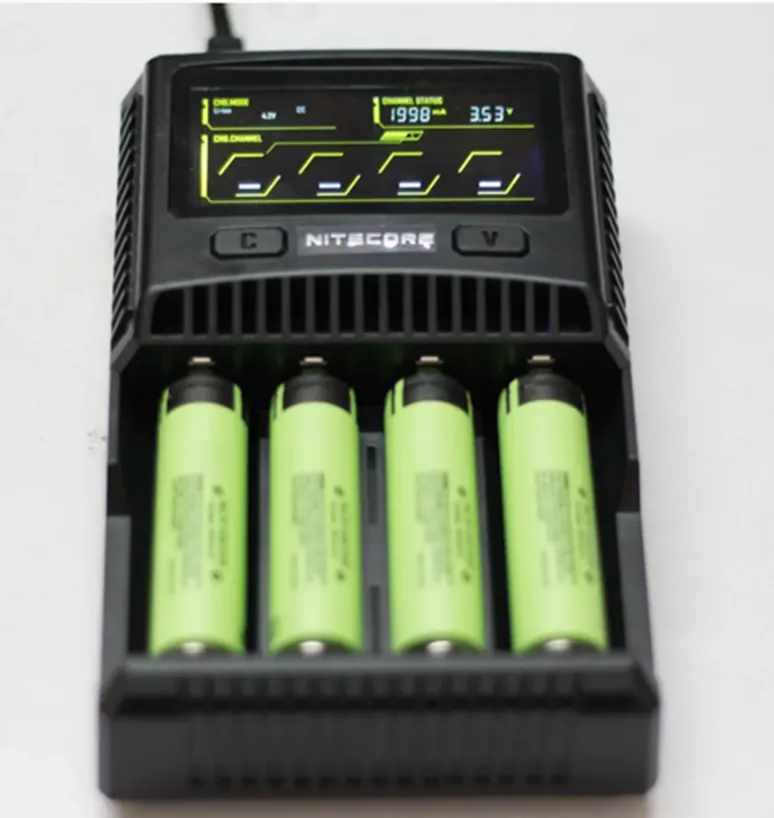
Fig 1.3
3. Design of cell holder
The main function of a battery holder is to keep cells fixed in place safely and securely also it is used to keep cells in a proper arrangement so that there will be a decrease in mechanical vibration, and have a better thermal runway in between the gaps of the cell. Most of the cell holder is made up of polypropylene or nylon bodies rated for 80–100°C.

Fig 1.4
4. Inserting cell inside the holder
Insert the cells inside these connectors with positive and negative poles kept alternatively in adjacent rows.
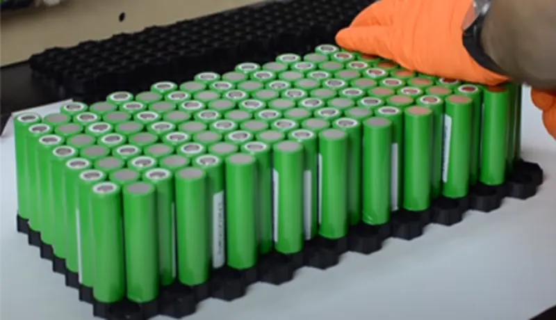
Fig 1.5
5. Inter connecting the cell
Now we have to arrange the cells properly for making the electrical connection among them. Place the first parallel group of cells positive side up, then place the second parallel group negative side up and then finally the last parallel group positive side up. We can assemble the cells to make the pack by using hot glue or by using plastic battery holder to assemble the cells. It provides space between the cells, which allow fresh air to pass and the battery get cooled easily. It also makes our battery pack solid and reliable and provide safety anti vibration to our battery pack.
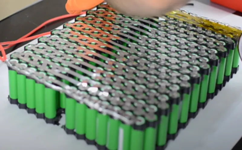
Fig 1.6
6. Check the battery pack capacity and the voltage
To make the battery pack, you have to first finalize the nominal voltage and capacity of the pack. Either it will be in terms of Volt, mAh/Ah, or Wh. You have to connect the cells in parallel to reach the desired capacity (mAh) and connect such parallel group in series to achieve the nominal voltage (Volt).
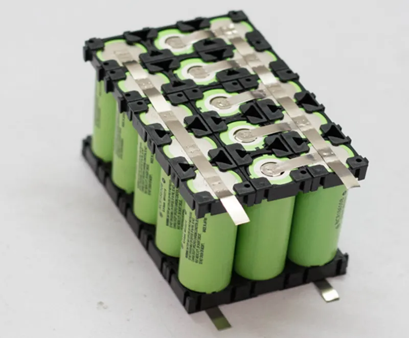
Fig 1.7
7. Spot welding
We have two options two connect the ANR26650M1-B cells together:
- Soldering
- Spot Welding
The best choice is always Spot welding, but Spot Welder is much costlier than a good quality Soldering Iron.

Fig 1.8
- To make the battery pack, we have to connect the cells together by means of Nickel strips or thick wire.
- Generally, Nickel strips are widely used for this.
- In general, two types of nickel strips are available in the market: nickel-plated steel strips and pure nickel strips.
- The pure nickel is little bit costlier than the nickel-plated steel, but it has much lower resistance. Low resistance means, less heat generation during the charging and discharging, which leads to longer useful battery life.
8. Installing the BMS
A battery management system (BMS) is any electronic system that manages a lithium battery pack and the main functionalities are :
- Monitors all of the parallel groups in the battery pack and disconnect it from the input power source when fully
- Balance all the cells voltage equally.
- Doesn't allow the pack from over-discharged.
The BMS has four soldering pads: B-, B1, B2, and B+. You have to connect the first parallel group negative terminal bus to the B- and positive terminal bus to the B1. Similarly, the third parallel group negative terminal bus to the B2 and positive terminal bus to the B+. You can spot weld the nickel strips to the BMS or solder it to the PCB pad. I preferred to solder the nickel strips to the PCB for a sturdy connection. First, apply soldering flux to the PCB pads and end of the nickel strips. After that tin all the pads by applying a little amount of solder and then solder them together.
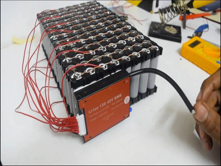
Fig 1.9
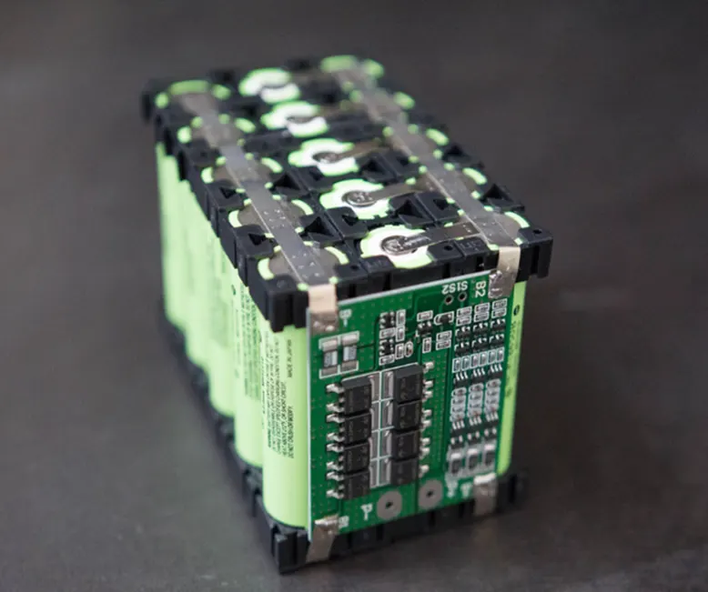
Fig 1.10
10. Installing cooling structure
Install cooling structures for air cooling/ liquid cooling as shown.
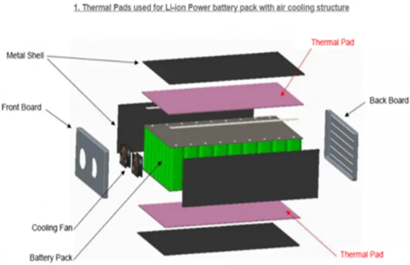
Fig 1.11
11. Installing the battery pack inside the enclosure
The battery pack is installed in the enclosure as shown
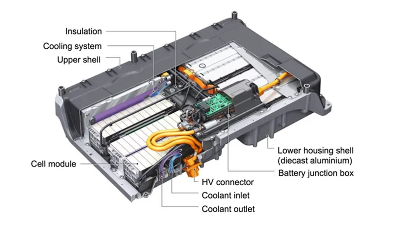
Fig 1.12
CONCLUSION
To develop a battery pack of 18KW using ANR26650M1-B cells along with their mechanical design.
REFERENCE