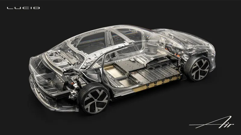
Project 1 Mechanical design of battery pack
AIM: Mechanical design of battery pack
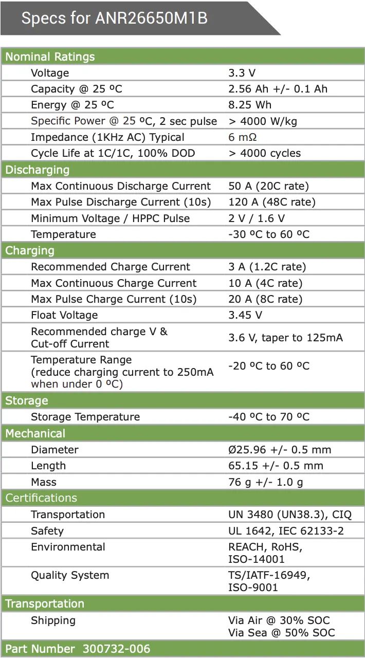
Given Cell: ANR26650M1-B
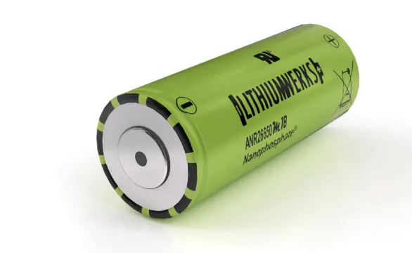
Lithium Werks’ 26650 cells are best for Power, Safety, Life applications. They deliver very high power due to their use of patented Nanophosphate battery technology. Based on lithium iron phosphate chemistry (LiFePO4 ), the cells are inherently safe over a wide range of temperatures and conditions. Whether the application requires outstanding cycle life or stable float reliability, the Lithium Werks’ 26650 cells are suitable for a wide variety of power, pulse, or stand-by applications.
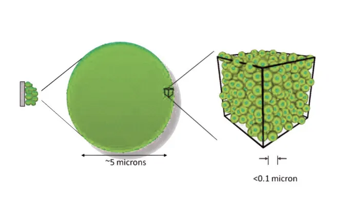
Nanophosphate® battery technology offers thermal-stable chemistry, faster charging, consistent output, low capacity loss over time, and superior total cost of ownership (TCO). It provides the foundation for safe systems while meeting the most demanding customer requirements. Multiple layers of protection are employed at the chemistry, cell and system level to achieve an energy storage solution with superior safety and abuse tolerance compared to metal oxide lithium-ion chemistries.
Applications:
- Energy storage
- Frequency regulation
- Uninterruptible Power Supplies
- Communication technologies
- Aviation/Aerospace
- Electrified mobility devices
- Industrial equipment
- Medical devices
- Consumer Products
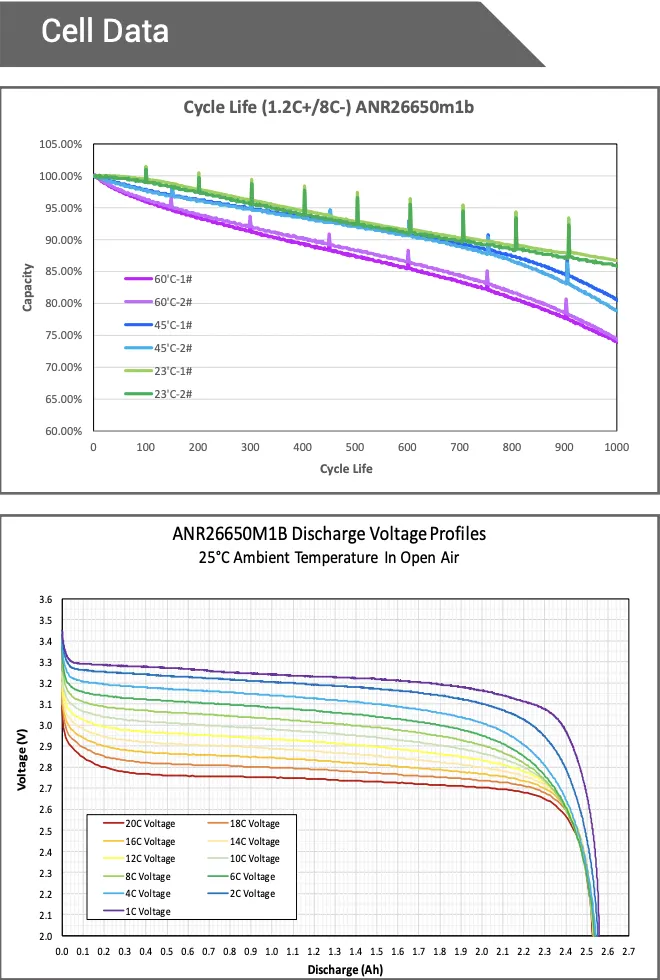
Detailed Battery pack drawing along with enclosure for a capacity of 18 KWh of cell model
ANR26650M1-B:
The purpose of a battery pack is to provide a convenient integrated power source for portable applications.The pack may fulfil several functions:-
- It enables higher voltage or higher capacity batteries to be built up from low voltage, low capacity cells.
- It houses a cell or a bank of cells together with the associated interconnections in a single convenient pack.
- It accommodates any necessary monitoring and electronic protection devices or circuits within the pack.
- It can accommodate additional circuitry such as indicator lights, heaters, cooling ducts and solar panels.
- It matches and meshes with the cavity in the product which the battery is intended to power providing both electrical and mechanical interfaces.
- It can provide unique electrical and mechanical interfaces to ensure compatibility both of the battery with the intended product and the charger with the battery.
Capacity and Voltage:
With a simple series chain of cells, the battery capacity in AmpHours is the same as the capacity of the individual cells since the current flows equally through all the cells in the chain.
High battery voltages are achieved by adding more cells in a series chain. The voltage of the battery is the voltage of a single cell multiplied by the number of cells in the chain. This does not increase the AmpHour capacity of the battery , but it increases the WattHour capacity, or the total stored energy, in proportion to the number of cells in the chain.
Battery capacity can increased through adding more parallel cells. This increases the AmpHour capacity as well as the WattHour capacity without increasing the battery voltage. For batteries with parallel chains the capacity of the battery is the capacity of the individual chain multiplied by the number of parallel chains.
Whereas cell voltage is fixed by the cell chemistry, cell capacity depends on the surface area of the electrodes and the volume of the electrolyte, - that is, the physical size of the cell. If at all possible the number of cells in a pack should be minimised to simplify the design and to minimise potential reliability problems. Fewer cells require fewer support electronics. Thus parallel chains should be avoided by specifying the highest capacity cells available. Design issues for multi-cell batteries are considered further in the section on Cell Balancing.
Cell Configuration:
The ultimate shape and dimensions of the battery pack are mostly governed by the cavity which is planned to house it within the intended application. This in turn dictates the possible cell sizes and layouts which can be used. Prismatic cells provide the best space utilisation, however cylindrical cells provide simpler cooling options for high power batteries. The use of pouch cells provides the product designer more freedom in specifying the shape of the battery cavity permitting very compact designs.
The orientation of the cells is designed to minimise the interconnections between the cells.
Battery Pack Energy capacity is 18KWh, for this we are calculating the no of cells required in series and parallel combination and also the Ampere Hour Capacity.
Here we are designing a high voltage battery pack for a small 4 seater electric car and its range is 300km. For this calculation the assumed voltage is 200v which is the nominal voltage for series connection.
As we assumed the vehicle range is 300km then the Average energy per km is
Total energy of battery pack/Range in km = 18000/300 = 60 Wh/km
Assuming the complete battery pack voltage : V = 200
Nominal voltage of each cell : 3.3V
Total battery pack voltage / Nominal cell voltage = 200/3.3 = 60V --------------------(1)
Total Energy capacity / Total battery pack voltage = 18000 watts / 200 V = 90Ah
Dicharge Current Capacity of Total Batttery Pack : 90Ah
Nominal cell capacity : 2.5Ah
Total battery pack capacity / Nominal cell capacity = 90Ah / 2.5Ah = 36Ah -----------(2)
- From (1) we get the no of cells required in series = 60S
- From (2) we get the no of cells required in parallel = 36P
The Battery pack specifications are : Energy capacity = 18KWh
Nominal Voltage = 200V
Maximum capacity = 90Ah
Pack combination = 60S36P
Total no of cells = 60*36 = 2160 cells
- In series connection the voltage increases and the current remains the same = 60*3.3 = 200Volts
- In parallel connection the current increases and the voltage remains the same = 2.5*36 = 90Amp
Mass of battery pack = Total no of cells * Mass of single cell
= 2160 *0.076
= 164.16 kg
Total volume of battery interms of area = Total no of cells in a battery pack * volume of single cell
= 2160*0.0345
= 72.89 m^3
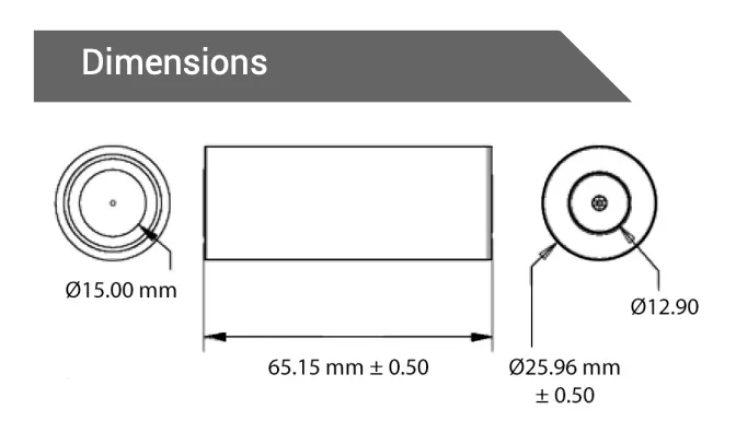
Considering the Single cell dimensions :
Diameter = 26 mm = 0.026m
Length = 65 mm = 0.065m
Mass = 76g = 0.076 kg
single cell voltage = 3.3V
capacity = 2.5 Ah = 1C Rate
Max continuous charge rate = 10A @ 4C Rate
Single cell volume = 3.14*0.026^2*0.065 = 0.03451 m^3
The volume of each cell is used to find the total volume of battery pack = cell capacity*cell voltage
= 2.6*3.3
= 8.58 Wh
Energy density of single cell is used to calculate the total energy density of battery pack:
volumetric energy (Wh/m^3) = Single cell energy / volume of each cell
= 8.58 Wh/0.03451 m^3
= 248.62 Wh/m^3
Gravimetric energy (Wh/Kg) = single cell energy / Mass of each cell
= 8.58 Wh/0.076 kg
= 112.89 Wh/kg
cell peak current(A) = Max charge current(C rate) * single cell capacity
= 10*2.5
= 25A
Battery pack peak current(A) = Cell peak current * No of cells connected in parallel
= 25*36
= 900 A
Battery pack peak power(W) = Battery pack peak current*Voltage if cells connected in series
= 900*200
= 180 kw
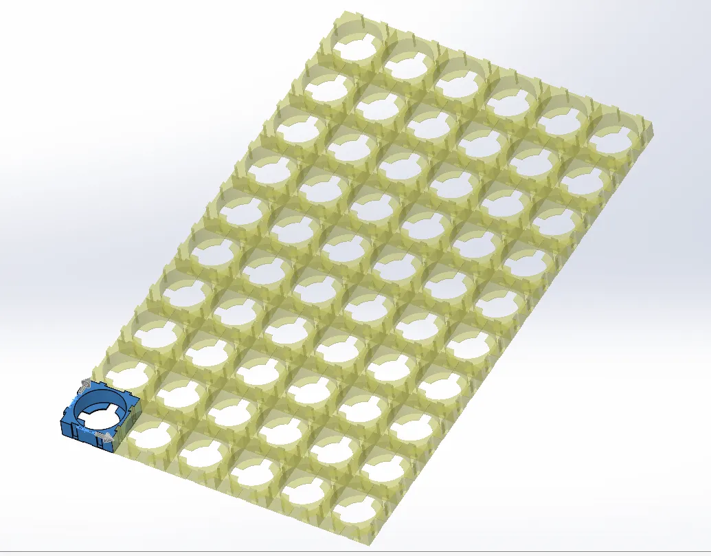
Cell holder dimensions:
- Height = 10mm
- length = 29mm
- width = 29mm
- weight = 5gm
Arrangement of cells in 60S36P together is not the best arrangement as it will take
29mm*60 cells =1740mm (For 60 cells in series)
29mm*36 cells =1044mm (For 36 cells in parallel)
so, a total of (1740*1044) space required and all the cells in a single matrix will lead to poor thermal management as we are employing the air cooled technique in the battry pack the ventilators will not be able to cool the inner cells as the air will not reach till the inner cells.
Also, according to the 18KWh capacity, the application might be in a small 4 seater Electric car the area taken by the battery pack assembly is 1.74*1.04 meters.
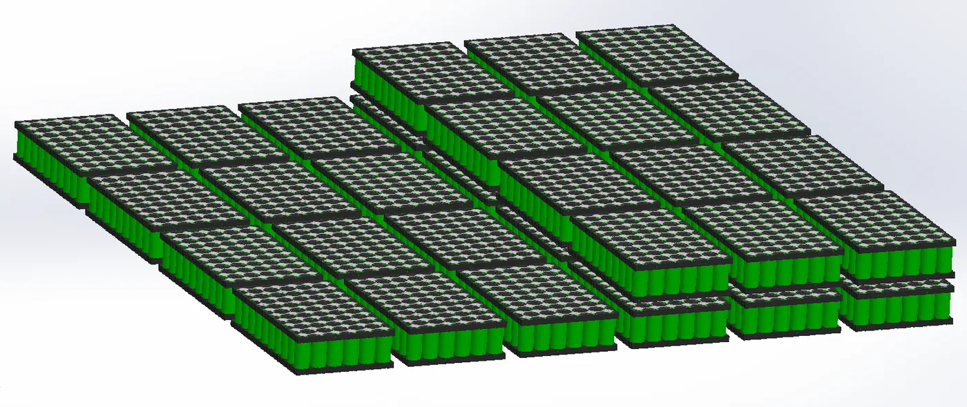
The solution for both the space required and the thermal management of battery pack is to create a module of 10S6P. This will create 33V 15Ah module. Arranging such 10S6P modules in 6S6P manner will create a 60S36P array giving 198V 90Ah.
Step 1: Arange all the cell holders in 10S6P manner
Step 2: Arange all the cells in cell holders in 10S6P manner
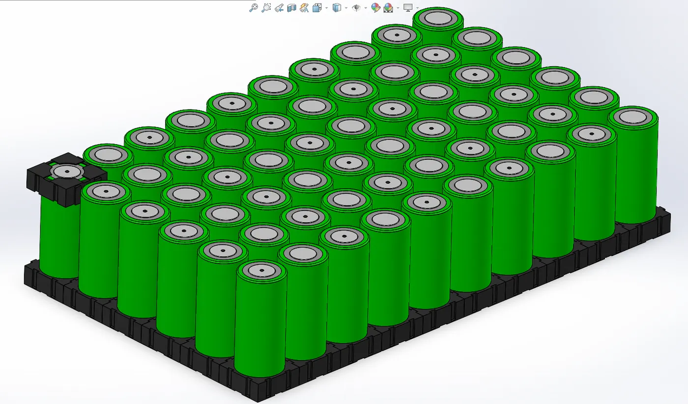
Step3: Add cell holders on the upper side of cells and also add nickel strips for series and parallel connections
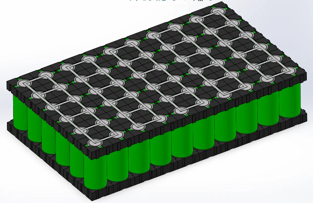
Now one module is complete and such 36 modules are required for 6 series and 6 parallel connection. The below image shows the arrangement of 36 such modules this completes the battery pack assembly with the required combination of cells.
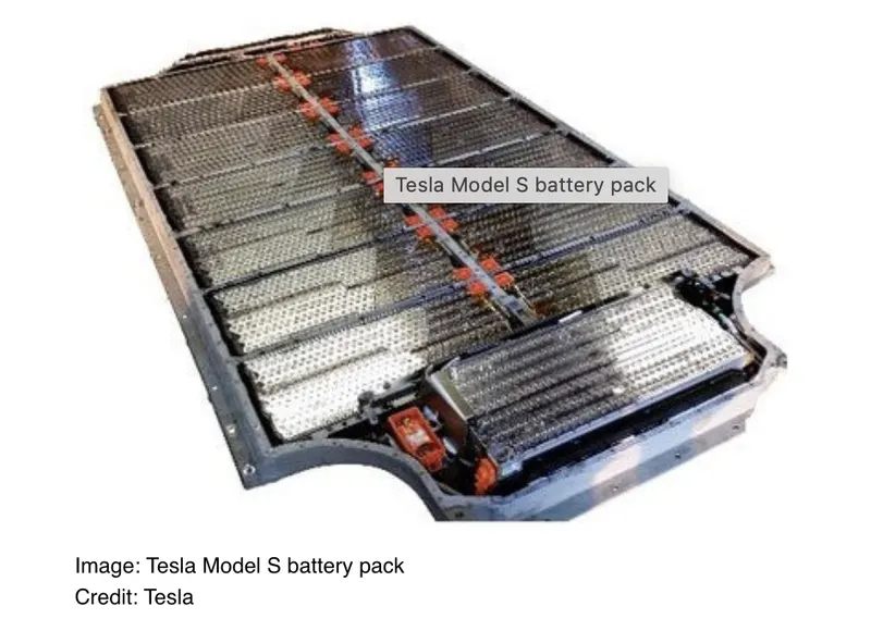
Tesla Model S battery pack:
Battery Management Systems:
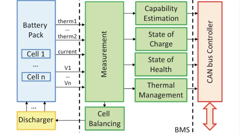
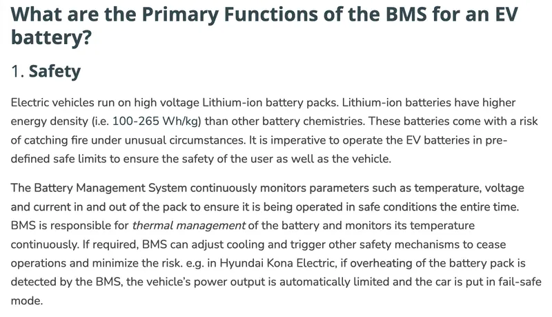
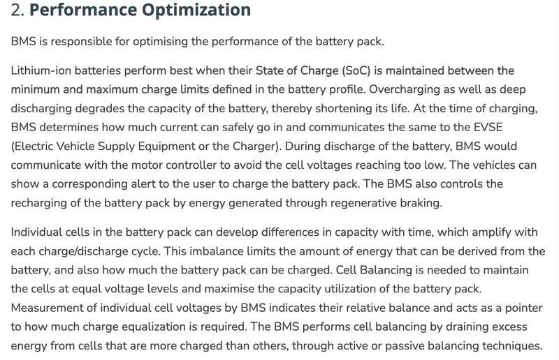
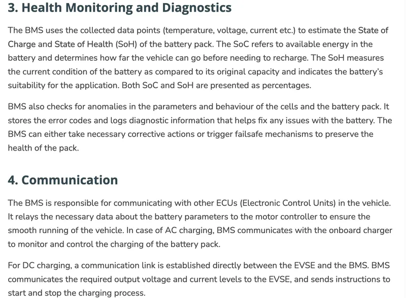
BMS is an electronic system that manages a rechargeable battery to ensure it operates safely and efficiently. BMS is designed to monitor the parameters associated with the battery pack and its individual cells, apply the collected data to eliminate safety risks and optimise the battery performance.
Thermal Management of battery:
- The importance of a cooling system
While advancements have been made in electric vehicles batteries that allow them to deliver more power and require less frequent changes, one of the biggest challenges that remain for battery safety is the ability to design an effective cooling system.
Batteries work based on the principle of voltage differential and at high temperature, the electron inside becomes excited which deserves the difference in voltage between the two sides of the battery. Because batteries are only manufactured to work between certain temperature extremes, they will stop working if there is no cooling system to keep it in working range.
If there is a larger internal temperature difference it can lead to different charge and discharge rates for each cell and deteriorate the battery pack performance. potential thermal stability issues such as capacity degradation, thermal runaway, and fire explosion could occur if the battery overheats or if there is nonuniform temperature distribution in the battery pack. In the face of life-threatening safety issues, innovation is continually happening in the electric vehicle industry to improve the battery cooling system.
- TYPE OF COOLING SYSTEM
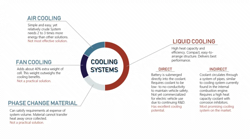
There are various types of cooling systems that can be used for the requirement of the vehicle. There is a various cooling system that can be used according to the requirement of the vehicle. There are air cooling systems, liquid cooling systems, and fan cooling systems. The air cooling system is the easy yet relative crude system needs 2 -3 times more energy than other solution. Were the liquid cooling system is a high heat capacity and efficiency. compact easy to arrange structure and deliver the best performance.
2 different methods are used for cooling the battery Direct method and indirect method
Direct method
The battery is submerged directly into the coolant. Requires coolant to be low to no conductivity to maintain vehicle safety. Not yet commercialized for electric vehicle use due to continuous R&D.
Indirect method
Coolant circulates through a system of pipes similar to the cooling system currently found in the internal combustion engine. Required a high heat capacity coolant with corrosion inhibitors.
Battery Packing:
The battery casing has to provide the mechanical and electrical interfaces to the product it is designed to power as well as to contain all the components outlined above. This is how the battery pack will be which is manufactured by the companies and employed in an Electric Vehicle.