Project 1 Mechanical design of battery pack
Battery pack capacity: 18 kWh
Cell: ANR26650M1-B
Prepare a detailed battery pack drawing along with its enclosure. State your assumptions
Aim- detailed battery pack drawing along with its enclosure
A123’s high-performance Nanophosphate® lithium iron phosphate (LiFePO4) battery technology delivers high power and energy density combined with excellent safety performance and extensive life cycling in a lighter weight, more compact package. Our cells have low capacity loss and impedance growth over time as well as high usable energy over a wide state of charge (SOC) range, allowing our systems to meet end-of-life power and energy requirements with minimal pack oversizing
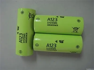
Fig- 26650 cell
- COMMERCIAL SOLUTIONS
Advanced lead acid replacement batteries for:
Datacenter UPS
Telecom backup
IT backup
Autonomously guided vehicles (AGVs)
Industrial robotics and material handling equipment
- GOVERNMENT SOLUTIONS
Military vehicles
Military power grids
Soldier power
Directed energy
- GRID SOLUTIONS
Frequency regulation
Renewables integration
Reserve capacity
Transmission and distribution
- TRANSPORTATION SOLUTIONS
Hybrid, plug-in hybrid and electric vehicle battery systems for:
Commercial vehicles
Off-highway vehicles
Passenger vehicles
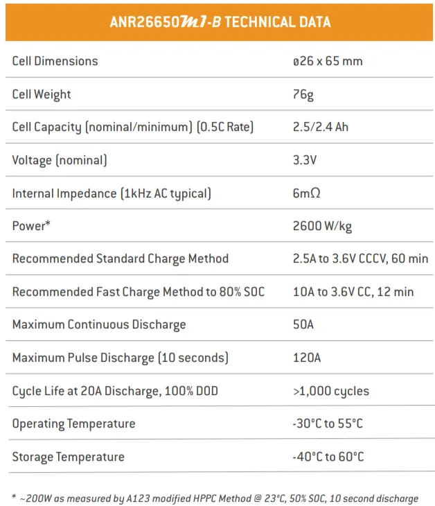
- Battery Specifications
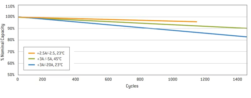
- Cycle Life Performance, 100% DOD, Various Temperatures and Discharge Rates:
- 2.5C Constant Current Discharge at Various Temperatures:
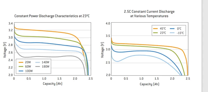
Lithium-ion cells can charge between 0°C and 60°C and can discharge between -20°C and 60°C. A standard operating temperature of 25±2°C during charge and discharge allows for the performance of the cell as per its datasheet.
The discharge current, in amps (A), is expressed as a fraction of the numerical value of C. Typical tubular positive lead-acid cell behavior at various discharge currents. For example, 0.2 C means C/5 A, and discharging will take approximately 5 hours. If C = 40 Ah, a current of 4 A can be expressed as 0.1 C
- Mechanical Design of battery pack:
The high voltage battery it is one of the most important component of a battery electric vehicle (BEV). The battery parameters have a significant influence on other components and attributes of the vehicle, like:
- maximum traction motor torque
- maximum regeneration brake torque
- vehicle range
- vehicle total weight
- vehicle price
Pretty much all major aspects of a pure electric vehicle (EV) depend on the parameters of the high voltage battery.
For our electric vehicle battery design we are going to start from 4 core input parameters:
- chemistry
- voltage
- average energy consumption of the vehicle on a driving cycle
- vehicle range
A battery consists of one or more electrochemical cells (battery cells) which are converting chemical energy into electrical energy (during discharging) and electrical energy into chemical energy (during charging). The type of elements contained within a battery and the chemical reactions during discharging-charging events define the chemistry of a battery.
A battery cell consists of five major components: electrodes – anode and cathode, separators, terminals, electrolyte and a case or enclosure. For automotive applications there are different types of cells used:
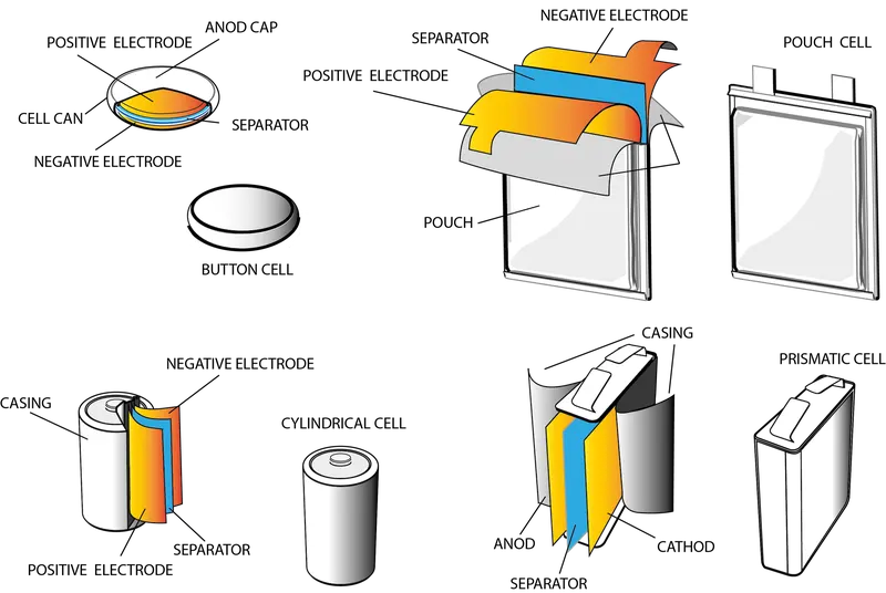
fig- Cell construction
Individual battery cells are grouped together into a single mechanical and electrical unit called a battery module. The modules are electrically connected to form a battery pack.
There are several types of batteries (chemistry) used in hybrid and electric vehicle propulsion systems but we are going to consider only Lithium-ion cells. The main reason is that Li-ion batteries have higher specific energy [Wh/kg] and specific power [W/kg] compared with other types
- Cell
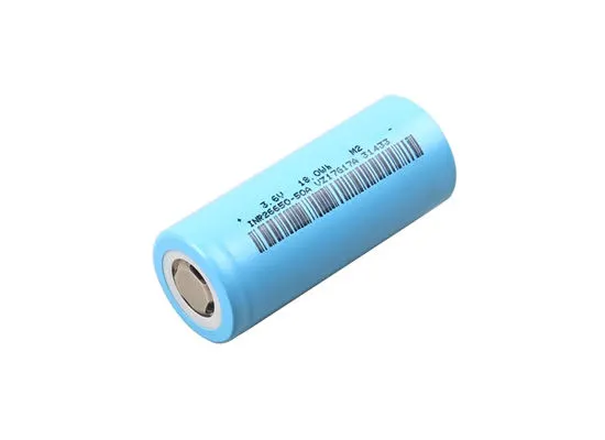
The LithiumWerks ANR26650M1-B is the next generation of A123 Systems' pioneering 26650 cylindrical cell, now with greater power and energy density and lower impedance. This versatile lithium ion cell is suitable for a wide variety of applications and system designs.
- Module
A battery management system (BMS) is any electronic system that manages a rechargeable battery (cell or battery pack), such as by protecting the battery from operating outside its safe operating area, monitoring its state, calculating secondary data, reporting that data, controlling its environment.
- BAttery pack
A battery pack is a set of any number of (preferably) identical batteries or individual battery cells. They may be configured in a series, parallel or a mixture of both to deliver the desired voltage, capacity, or power density.

Fig- Battery pack
- Ragone Chart
The Ragone plot was first used to compare performance of Batteries.However, it is suitable for comparing any energy-storage devices, as well as energy devices such as engines, gas turbines, and fuel cells.
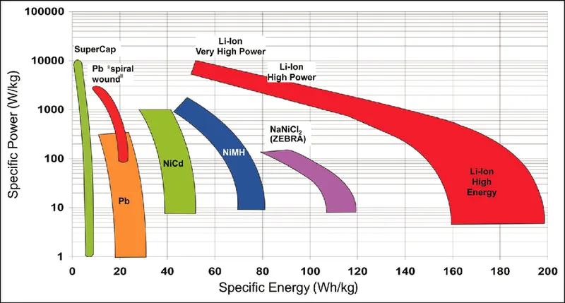
Fig- Ragone chart
Conceptually, the vertical axis describes how much energy is available per unit mass, while the horizontal axis shows how quickly that energy can be delivered, otherwise known as power per unit mass. A point in a Ragone plot represents a particular energy device or technology.
The amount of time (in hours) during which a device can be operated at its rated power is given as the ratio between the specific energy (Y-axis) and the specific power (X-axis). This is true regardless of the overall scale of the device, since a larger device would have proportional increases in both power and energy. Consequently, the iso curve (constant operating time) in a Ragone plot are straight lines.
For electrical systems, the following equations are relevant:
- {\displaystyle {\text{specific energy}}={\frac {V\times I\times t}{m}},}

- {\displaystyle {\text{specific power}}={\frac {V\times I}{m}},}

- EV design - Battery calculation:
Assumptions:
Battery energy = 18 kwh
Voltage (to run the vehicle) = 400V
(i) Energy = 18 kWh
(ii) Number of cells (N) = energy / (nominal voltage*capacity)
N = 18000 / (3.3*2.5)
N = 2182
We need a minimum of 2182 cells to get 18 kWh energy, now based on that, we need to decide configuration – series and parallel.
In series configuration capacity remains the same and voltage will be the sum of individual cell voltage.
In a parallel configuration, the voltage remains the same and capacity accumulates.
And we assumed 400 Volts are need to run the vehicle.
The nominal voltage of one cell is 3.3 V
Number of series cells required to produce 400 V (Ns) = voltage required / nominal voltage of one cell
Ns = 400 / 3.3
Ns = 121.21 = 122
122 cells are connected in series will generate 400 voltage and the capacity of the whole module will be 2.5 Ah
Now we need to find the number of cells which will be connected in a parallel configuration
Np (cell in parallel) = total cell / Ns
Np = 2182 / 122
Np = 17.8 = 18
Hence we take 18 cells for each parallel row, although it is exceeding the required capacity, that is negligible.
Cell architecture = 122 Series and 18 Parallel = 122S18P
(iii) Battery capacity:
We know parallel configured cell multiplies individual cell capacity so,
Capacity = parallel cell row*individual cell capacity
Capacity = 18 * 2.5
Capacity = 45 Ah
(iv) Current supplied by the battery
We have already calculated battery capacity which is 45 Ah means it is going to supply 45 A current per hour. which can be considered as C-rate.
(v) Range:
Let’s powertrain energy consumption = 100 Wh/km at 70% powertrain efficiency
Range = Capacity / energy consumed per kilometre
Range = 18000 / 100
Range = 180 km
So,our vehicle will be able to cover around 180 km with current parameters.
(vi) Internal Resistance of Battery:
The entire resistance encountered by a current as if it flows through a battery from the negative terminal to the positive terminal is known as internal resistance of battery.
(vii) Battery Dimensions:
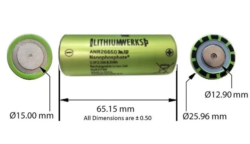
Fig- Cell dimensions
ANR26650 cell has 26mm diameter and 65mm height. On the basis of that we need to decide battery size of battery casing.
Length of casing (L) = number of cells at series*(cell diameter (26) + margin at both side of cell (4)) + clearance at side (diameter of edged cell + margin)
L = 122*30 + 60
L = 3720 mm
Breadth of casing (B) = number of cells at parallel*(cell diameter (26) + margin at both side of cell (4) + clearance at side (diameter of edged cell + margin)
B = 18*30 + 60
B = 600 mm
Height of casing (H) = 65+35 (Height of cell + margin for wiring ,Cell holders and metal strips)
H = 100 mm
(viii) Weight of battery pack
Cell weight = 76g
Number of the cells = 2182
Battery pack weight (W) = cell weight*number of cells + weight of accessories
W = 76*2182 + 4.5 = 165.8 + 4.5 = 170.3 kg
Cylindrical battery pack assembly equipment:
|
Product Name |
Description |
|
Automatic Cylindrical Battery PVC Heat Shrink Wrapping Machine |
Film speed:50~70PCS/MIN Film precision:±0.1MM |
|
512 Channel Battery Tester |
5V 2A/3A/5A/6A 512 Channel Battery Testser optional |
|
Battery Labling Insulation Paper Sticking/Pasting Machine |
Sticker Matrials:Barley paper or PVC Barley paper Maxium 350mm;Scroll Internal Diameter 72-75MM |
|
Battery Sorting Machine |
(5/6/9/11/13/22 Channel Battery Sorter optional) Data record funtion is selectable |
|
Manual Spot Welding Machine |
Pneumatic AC Spot Welding Machine (Single Welding Point or Doubel Welding Point) |
|
Manual Spot Welding Machine |
AC Pedal Manual Spot Welding Machine |
|
Manual Spot Welding Machine |
AC Pulse Pneumatic Spot Welding Machine |
|
Manual Spot Welding Machine |
DC Output Spot Welding Machine |
|
Manual Spot Welding Machine |
5000A/8000A Pneumatic Inverter DC Spot Welding Machine |
|
Automatic Spot Welding Machine |
Double Sides Spot Welding Machine |
|
1-24 series or 1-32 series BMS Tester |
Over-discharge Protection Current:0-120A Overcharge Protection Current:0-50A Overcharge/Overdischarge Voltage:0.5-5V |
|
Battery Comprehensive Tester |
100V 120A 18650 Battery Pack Comprehensive Tester |
|
Aging Machine |
30 V 10A Charging 20 A Discharging Aging Machine |
|
Aging Machine |
70 V 5A Charging 10 A Discharging Aging Machine |
|
Aging Machine |
100 V 10A Charging 20 A Discharging Aging Machine |
- Cell manufacturing
A steel container forms the battery casing, which holds the electrodes, an anode (the negative terminal) and a cathode (the positive terminal). The cathode consists of silvery matte rings made of manganese dioxide, graphite and electrolyte. The anode is the zinc paste located inside the separator.
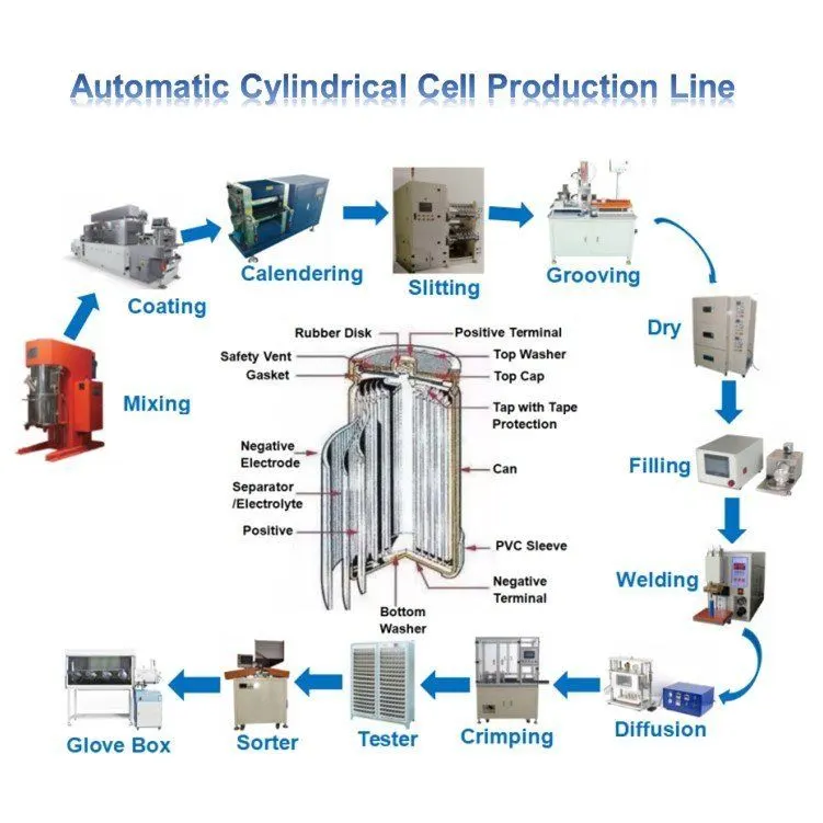
Enclosures:
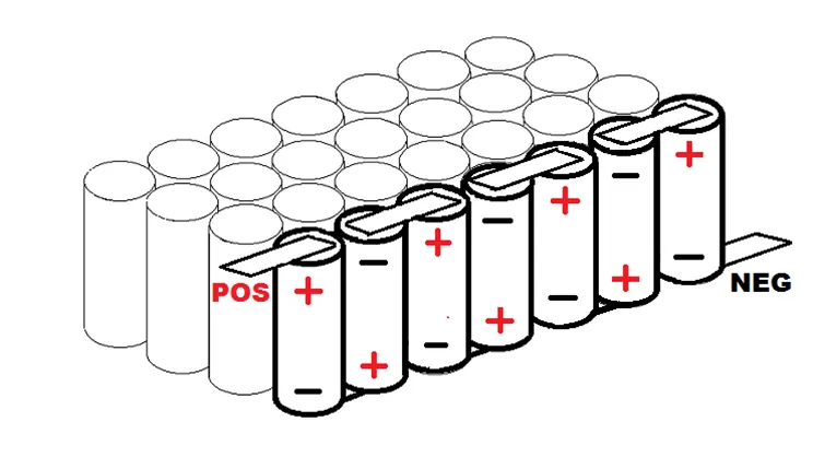
Cells in series connection-
When you connect cells together in series, it doesn’t change the amps or the capacity, it only raises the voltage of the pack. Hooking them up in series means that you connect the positive end
of one cell (or P-group) to the negative end of the other as shown below.
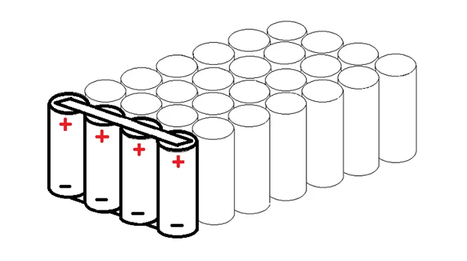
Cells in Parallel connections-
If you take several cells and connect their same-type electrodes in parallel, they all will act as though they are one large cell. Also, when you first connect them to each other,
they must be at the same level of charge.
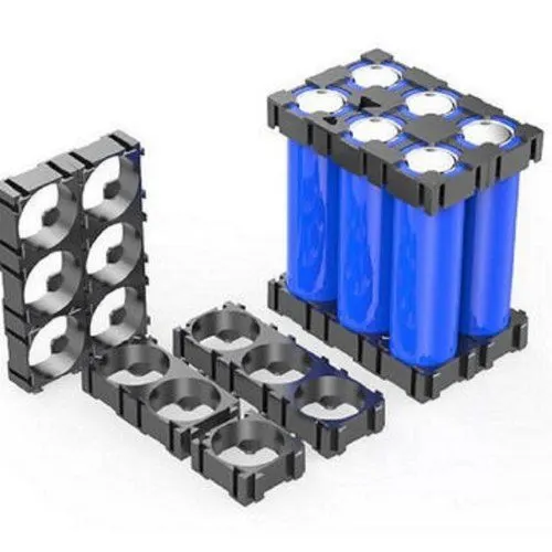
Cell holders-
These holders are used for holding the individual cells in a better posture without mis-assemble. The connections can be made accordingly to make series connections and
parallel connections to form the required module dimensions.
- Materials and process in battery pack construction:
Scientific literature concerning different joining technologies in the field of battery manufacturing is discussed based on those criteria. The most common joining techniques are ultrasonic welding, wire bonding, force fitting, soldering, laser beam welding, and resistance welding
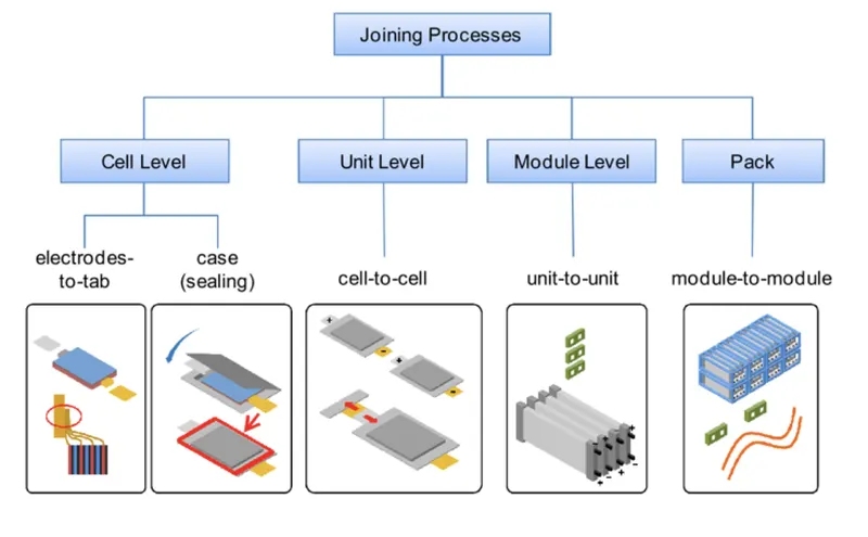
Battery pack constructions consist of three major levels of processings namely cell level,module level,pack level constructions. The electrodes are combined with electrolyte to various cell models as cylindrical,prismatic,pouch type cells. After case sealing cells are combained to form module level construction.Finally these modules are combained to form pack level constructions.
- Type of welding used
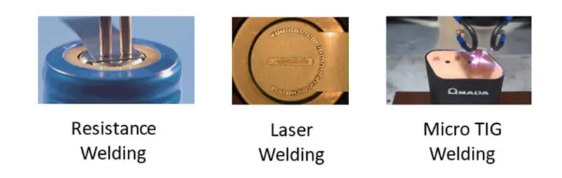
- Micro-Clinching
Clinching or micro-clinching is a mechanical interlocking mechanism of sheet metal parts,
especially used for automotive body-in-white, domestic appliances, or electronics joining
applications [19]. Clinching is a joining process in which a mechanical interlock (i.e., local deformation without use of any additional joining elements) is created by a tooling set (a punch and a die) as shown in Figure 4a. Clinching is a simple technique for point joining of metal sheets typically from 0.2 mm to 4 mm thick, to a total joint thickness of about 6 mm. Using the clinching, tab-to-tab joints are feasible. The feasibility of clinching as an alternative method of joining for pouch cell tab joining has been reported. Clinching may not be feasible for cylindrical/prismatic cells joining as access to the both sides of the assembly is required. Further, clinch joints are prone to becoming loose under vibration, moisture ingress, and so on.
- Soldering
Joining of dissimilar materials using this method is an established and tested technology within
the electronics industry. Soldering of a tab to a terminal of a cylindrical cell may be feasible. Soldering directly to a cell is not recommended as it is easy to melt or disturb the safety vent, compromise seals, or cause internal shorting if the heat is too high (i.e., heat input is the key soldering parameter). Further, it is feasible to solder pouch cell tabs if additional filler metal is used between the tabs. Special aggressive fluxes are required for joining aluminium, which is typically considered unattractive because of the potential for corrosion, reduction of joint strength under vibration, and creating debris. Therefore, soldering is unlikely to be of widespread interest for battery joining applications.
- Laser Welding
Laser welding uses a focused laser beam as a point source of energy to create localised heating to
join parts together. Because of the small cross section of the laser beam and its energy concentration, narrow and deep welds can be made with a high welding speed . Also, because of the narrow welds and high welding speed, the process generates a low level of heat in the assembly during welding , which is important for battery tab welding, as the chemicals inside the batteries are very heat sensitive. A schematic of fillet laser welding and application for prismatic cell-to-bus bar joining are shown in Figure 4b. When welding a tab to a terminal, generally, the tab should be thinner than the battery cell casing terminal. Process parameters need to be controlled to provide weld strength and conductivity without penetrating the battery case/can. Other applications include sealing of the battery casing for prismatic cells, and joining of tab-to-bus bar and bus bar-to-bus bar . As the weld pool from laser welding is very small, it has a very small gap tolerance, subsequently, during t
Conclusion:
Lithium Ion and Lithium Ion Polymer batteries are a great power source for some applications but they require preventive protection during discharging and charging.
- References
1. Faria, R.; Moura, P.; Delgado, J.; de Almeida, A.T. A Sustainability Assessment of Electric Vehicles as a Personal Mobility System. Energy Convers. Manag.
2. Whittingham, M.S. History, Evolution, and Future Status of Energy Storage. Proc. IEEE 2012, 100, 1518–1534.
3. Becker, J.; Nemeth, T.; Wegmann, R.; Sauer, D. Dimensioning and Optimization of Hybrid Li-Ion Battery Systems for EVs. World Electr. Veh. J. 2018, 9, 19.
4. Pfriem, M.; Gauterin, F. Development of Real-World Driving Cycles for Battery Electric Vehicles. World Electr. Veh. J. 2016, 8, 14–24.
5. JMBS. Our Guide to Batteries; Johnson Matthey Battery Systems: Milton Keynes, UK, 2015.