Project 1 Mechanical design of battery pack
Project 1 Mechanical design of battery pack
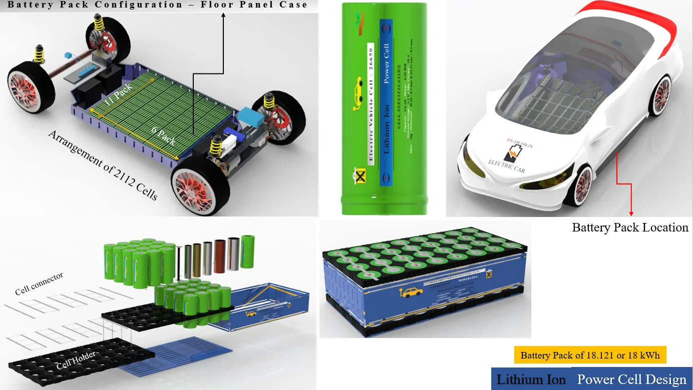
Battery pack capacity: 18 kWh
Cell: ANR26650M1-B
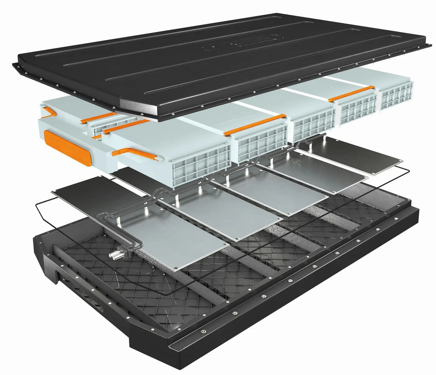
Prepare a detailed battery pack drawing along with its enclosure. State your assumptions.
Aim:
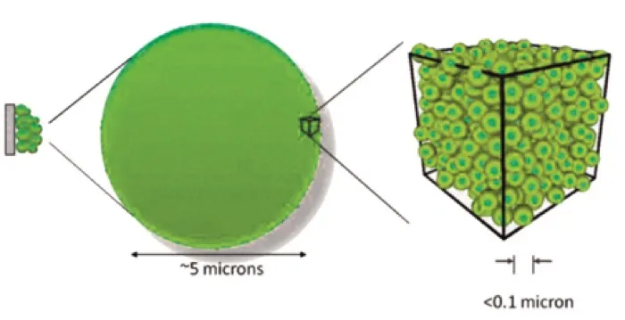

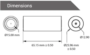
LITHIUM IRON PHOSPHATE: THE SAFER CHEMISTRY
LiFePO4 cells under puncture or short circuit conditions are much less likely to experience thermal runaway than (for example) lithium metal oxide. Punctured or short-circuited lithium metal oxide cells will cause heating, making the oxygen bonds prone to break, resulting in the release of oxygen and thermal runaway. This causes a fire with temperatures reaching up to 1000 degrees and self-perpetuated by released oxygen from within the metal oxide cathode materials. With lithium metal oxide cells, the bond with oxygen is much weaker than the oxygen bond with phosphorous in a phosphate thus permitting lithium metal oxide thermal runaway at much lower temperatures.
EV Battery Specs: Voltages and Capacities
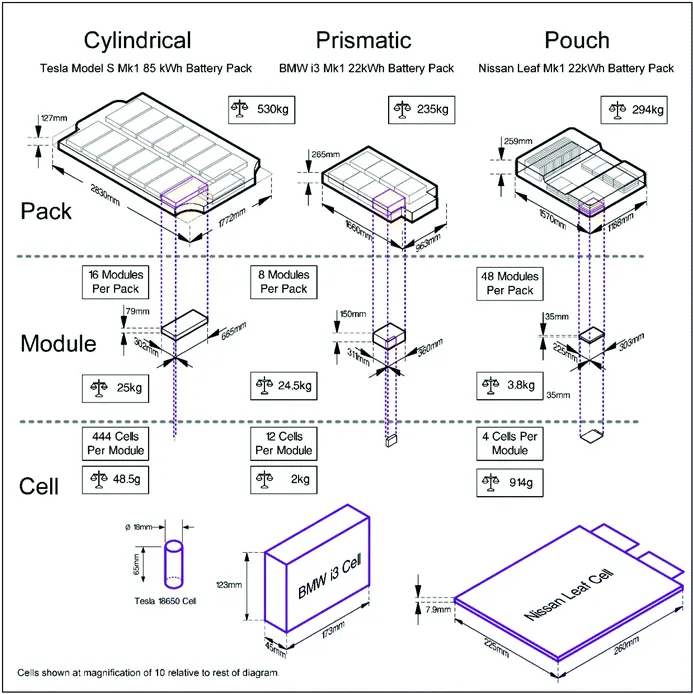
An electric vehicle battery is often composed of many hundreds of small, individual cells arranged in a series/parallel configuration to achieve the desired voltage and capacity in the final pack. A common pack is composed of blocks of 18-30 parallel cells in series to achieve the desired voltage. For example, a 400V nominal pack will often have around 96 series blocks (as in the Tesla Model 3).
Common nominal pack voltages in current vehicles range from 100V-200V for hybrid/plug-in hybrid vehicles and 400V to 800V and higher for electric-only vehicles. The reason for this is higher voltages allow more power to be transferred with less loss over the same diameter (and mass) of copper cable.
An example EV battery system with individual cells in series.
- I assume the overall voltage of the electric vehicle is 400V.
- And I constructed the battery pack of 18KWh for a 400V input motor voltage.
- To construct a battery pack initially I estimate the voltage requirement of the vehicle's overall load.
- I assumed 400V as mentioned above. then the battery modules should be created and the overall voltage is matched with the load requirement voltage.
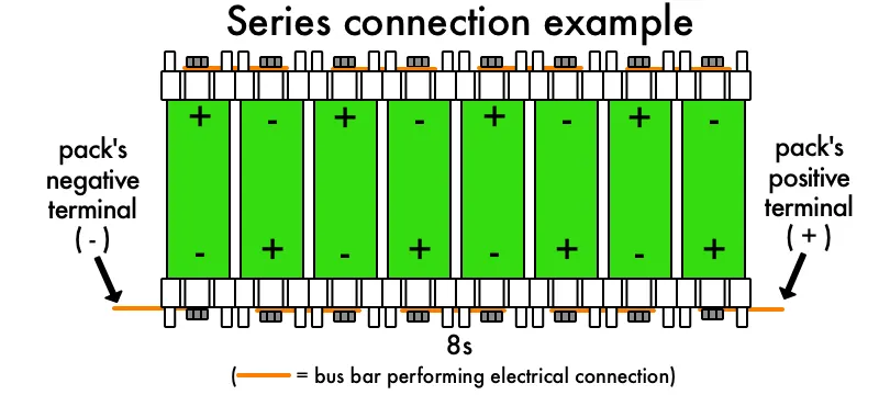
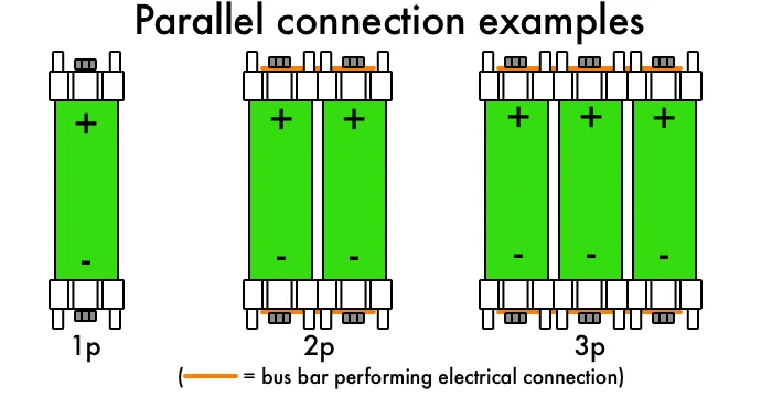
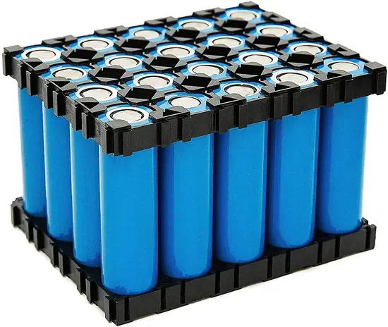
- The modules can be created in series/parallel connections of individual cells. Then every module should be connected in series/parallel to construct the final battery pack.
- In series connection-Voltage added and Current remains same.
- In Parallel, connection-Voltage remains the same, and Current gets added.
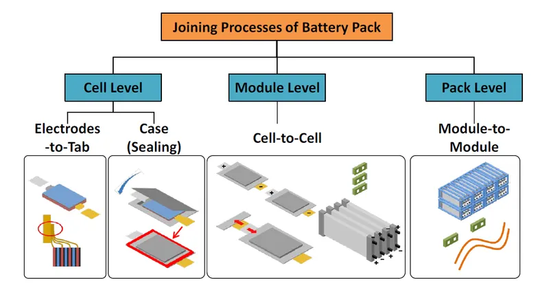
You have probably noticed the increasing numbers of electric vehicles and other transportation devices on the roads today including private automobiles, transportation trucks, bikes, motorcycles, scooters, and other modes of transportation driven by electrical power, all of which are provided by stored energy in batteries.
This electrification – which applies across several sectors – is neatly wrapped up in new terminology: eMobility, e-Mobility, or Electro Mobility. According to Gartner, eMobility “represents the concept of using electric powertrain technologies, in-vehicle information and communications technologies, and connected infrastructures to enable the electric propulsion of vehicles and fleets.” A BIG piece of the mobility puzzle is battery and battery pack manufacturing.
The challenges encountered in bringing this technology to market include the demand for reduced weight, expanded range, faster charge times, and lower costs. Translated into manufacturing goals, the batteries need to possess higher capacity with negligible energy loss delivering to the drivetrain, higher current carrying capacity for charging and be made of light-weight, lower-cost materials. And since the mobility market is so rapidly expanding, there are additional manufacturing challenges, including the demand for higher throughput and quality.
Some of these goals can be achieved by improved cell chemistries and battery pack design, but others can be improved only by considering the joint quality between the batteries and the current collectors.
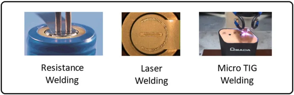
It’s a tall order, and that is why special attention must be paid to the welding system selected for EV battery pack manufacturing. In this post, we will examine the key challenges in tab-to-cell connection and see how the available welding technology options measure up. We’ll focus on:
- Resistance welding
- Laser welding
- Micro TIG welding
Another viable option – ultrasonic welding – is not covered in detail but is shown in a matrix summing up how the technologies compare.
Tab to Cell Connection Manufacturing Challenges
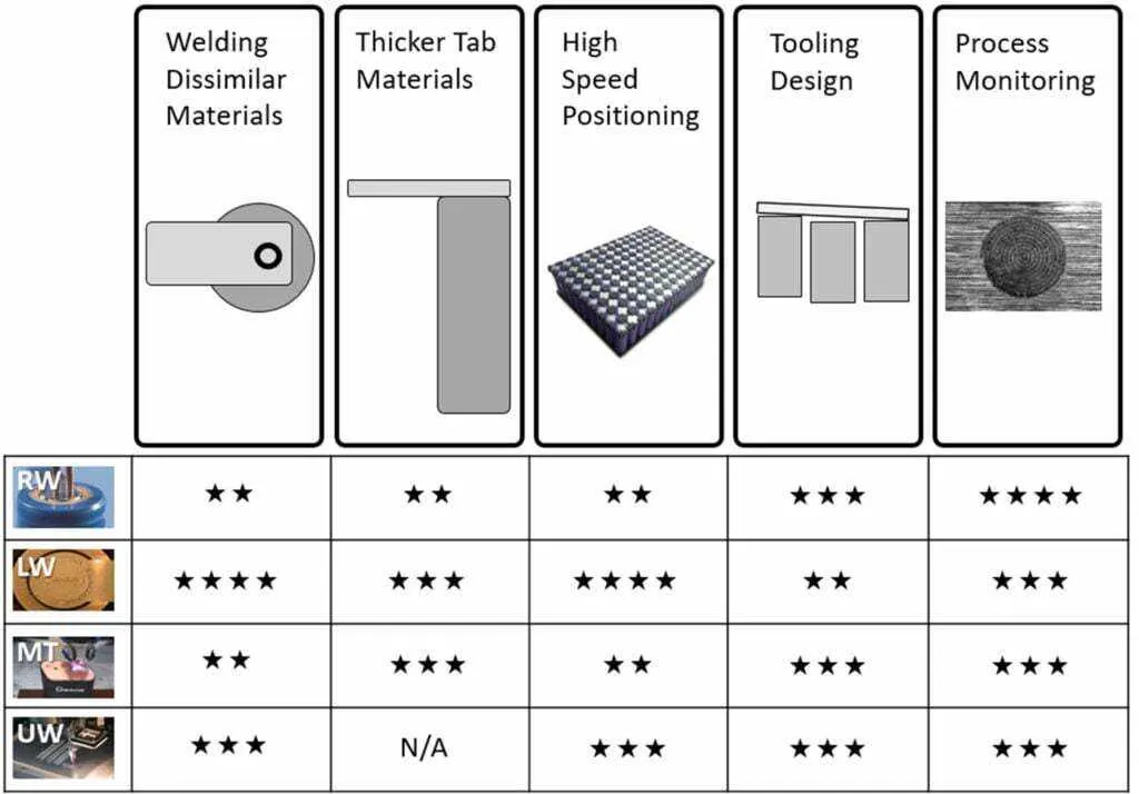
The challenges listed above can be broken down into desirable solutions. The following graphic shows five key challenges typically encountered in tab-to-cell battery connections:
- Dissimilar metal welding
- Thicker tab materials
- High-speed positioning
- Tooling design
- Process monitoring
Let’s see how the three welding technologies measure up:
DISSIMILAR METAL WELDING
In battery pack manufacturing, the cells are often already assembled and the engineer is challenged with coming up with a design to join them in series and parallel to deliver optimum energy. A typical Li-ion cell is constructed of nickel-plated cold-rolled steel. We know that we can easily join a nickel or steel tab to this material, but both materials possess high resistance.
Therefore, ideally, the engineer would choose a more conductive tab material like aluminum or copper – materials that will minimize thermal loss and provide a means to quickly discharge and charge the batteries. However, can these dissimilar materials be joined? Which welding technology is best? Let’s take a look.
Resistance Welding
Material conductivity somewhat limits the ability to join materials using resistance technology. As the name indicates, resistance is required to heat and melt the parts. When the material is conductive – like aluminum or copper – this technology is not suitable. Some novel alloys which combine both resistive and conductive material are starting to be used – like Ni SS Cu (SIGMAclad®), – which provides a resistive layer to make the weld and a conductive layer to meet the challenges above.
Micro TIG Welding
Micro TIG welding is strictly a fusion process, which limits materials to be joined to those with compatible chemistries: welding copper to steel is possible, but aluminum to steel is not.
Laser Welding
In general, laser welding is also a fusion welding process. However, new laser sources make it possible to avoid the traditional fusion process and join materials with limited intermetallic mixing. The resulting mechanical joint which is akin to Velcro® provides good electrical and thermal contact. This enables even the previously unthinkable joining of aluminum and cold rolled steel without forming the brittle intermetallic structure of a traditional fusion weld. The fitness and purpose of the weld need to be thoroughly tested, however. In the case of an aluminum battery tab to a nickel-plated cold rolled steel battery can the mechanical pull strength is quite strong along the direction of anticipated vibrations. Thermal and shock testing show that the resultant mechanical joint meets conductivity, strength, and overall durability requirements.
THICKER TAB MATERIALS
Why are battery manufacturers using thicker tab materials? Higher current carrying capability. However, thicker tabs also require more energy and more precise input to avoid burning through them and damaging the battery cell.
Resistance Welding
When using resistance spot welding, careful consideration of the current path between the electrodes must be considered. The electrons will always flow along the path of least resistance, thus as the tabs get thicker, the energy will travel directly between the electrodes with little to no energy at the desired interface. This starts to occur for nickel tabs >0.005” (125 microns). To avoid the shunting of current, the tab needs to be carefully designed with slots and tabs to concentrate the energy and guide the weld energy to specific spots.
Laser Welding
When laser welding, the joint geometry of the battery tab weld is a lap weld, which means the laser must penetrate fully through the top tab and at least slightly into the can wall. It is possible to reach very high penetrations (>0.4” or >10 mm) with single-mode fiber lasers, however, from a practical point of view the thickest tabs are on the order of 0.020” (500 microns) for can walls that are 0.012-0.014” (0.3-0.35 mm), though preferably the tab thickness of 0.010” (0.25 mm) is preferred to have best manufacturing success.
Micro TIG Welding
Micro TIG welding can also handle up to 0.020-inches (500 microns) thick material with a 200 A output power supply, but thicker tab material requires additional heat that can be a safety concern.
HIGH-SPEED POSITIONING
Battery modules are getting larger and larger and the demand for battery packs is ever-increasing. High-speed positioning, therefore, is a very desirable system feature resulting in increased product throughput. There are several critical factors affecting cycle time including the actuation/motion of the head, weld cycle time, and actuation/motion between cells that need to be considered for each welding technology.
Resistance Welding
There are a number of motion actuation and process times to be taken into account when using resistance welding. For each weld, the electrodes on the weld head must be lowered to the workpiece, squeeze time (is the amount of time to apply pressure until the weld fires) must be applied, and then there is the weld time, hold time (after weld fires and starts to cool), and finally raising the electrodes back to the home position.
One must also calculate the motion time to move from cell to cell.
A back-of-the-envelope type calculation is shown in Table 1. Per the site, it is estimated to take 2.2 seconds. For a battery pack consisting of 117 Cells (9 x 13), this means there are 234 sites to weld and a total process time of 514.8 seconds.
Laser Welding
Since laser welding is a non-contact process, the only motion is making a weld pattern and the motion moving the beam from cell to cell. The weld cycle time is a combination of shots and small motion on a cell.
For laser welding, the back-of-the-envelope calculation for the time to process 234 weld locations is estimated to be 257.4 seconds.
Micro TIG Welding
With Micro TIG welding, cycle time considerations include the motion of the torch going up and moving from cell to cell.
Because of the motion up and down of the torch, the weld time is longer than laser welding and is estimated to be 491.4 seconds.
Table 1 provides an overview of the cycle time comparison of the three technologies. Laser welding is significantly faster showing the allure of the laser for battery module welding. Cycle time can be reduced even further with the use of a galvo scanning system, where some motion is handled by quick motions in the galvo head, and then indexed after all cells within the welding field are addressed.
| RW | LW* | MT | |
| Motion from cell to cell | 1 s | 1 s | 1 s |
| Head actuation (down) | 0.5 s | N/A | 0.5 s |
| Weld cycle time | 200 ms | 100 ms | 100 ms |
| Head actuation(up) | 0.5 s | N/A | 0.5 s |
| TOTAL (per site) | 2.2 s | 1.5 s | 2.1 s |
| TOTAL (234 welds) | 514.8 s | 257.4 s | 491.4 s |
| *battery pack on XY table with fixed focus head | |||
Table 1- Estimation and comparison of cycle times for resistance welding (RW), Laser Welding (LW), and Micro TIG Welding (MT)
TOOLING DESIGN
The number one rule in welding is – you can’t weld air! In order to achieve a successful weld, the tab and cell must be in intimate contact. Some welding technologies have a built-in tooling mechanism because they are contact processes. Others are non-contact and require special production tooling to hold the parts in close contact when the energy is delivered.
As battery packs become larger, there are additional considerations to account for. For example, the welding system must account for varying cell heights and maintain flatness over larger modules. No matter which technology is used, the tooling design used to hold the parts must provide access to the weld area, cover part tolerances and meet production throughput requirements.
Resistance Welding
Resistance welding is essentially a self-tooling process; the electrodes come down on the parts forcing them into intimate contact. There are limitations to the amount of gap, but generally, this is the easiest of the technologies in this regard. Tooling is generally still required to hold multiple parts in place.
Laser Welding
Because laser welding is a non-contact welding process, it does not have the self-tooling properties of resistance welding. Tooling must be designed to hold the two parts in intimate contact. In general, it is best to hold as close as possible to the actual location of the weld to limit the chance that the tab material is deformed at the weld site. Also – special consideration for lasers – the tooling must not interfere with laser beam access. The laser is focused down onto the part forming a cone – this cone must be clear from any obstruction to deliver the right amount of energy to the part.
Micro TIG
Micro TIG welding – an arc welding process – is also a non-contact process. So like laser welding, a proper tool must be designed to hold the parts in intimate contact. Standard Micro TIG uses a fixed torch, with the ideal separation range of the electrode to the workpiece of between 1-3 mm (within 250 microns). The torch nozzle is often quite large in relation to the spot weld, which can make tooling design challenges. Some self-tooling concepts are available with the use of a copper sheath.
PROCESS MONITORING
The use of process monitoring is growing, based on the desire for higher throughput, increased safety, higher quality output, and the ability to trace products from cradle to grave. The challenge is to conduct monitoring in real-time.
Resistance Welding
Resistance weld monitors can measure current, voltage, force, displacement, and time. These weld checkers are well established in the industry. Specifically for battery packs, it is important to measure displacement (as the collapse of the projection) and voltage.
Laser Welding
Laser weld monitors are new to the scene, but have been gaining a foothold over the past 5 years. Different types of sensors can detect the signal array that is emitted during the laser-matter interaction. Types of signals include a reflection of the laser beam, thermal, visible light, and UV light. In addition, sound can also be recorded. These are all the signals above the surface of the part. It is also possible to look into the penetration of the laser energy into the part.
Micro TIG
Micro TIG weld monitors monitor current and voltage (after arc start).
While each monitor may check different parameters, all of the ones listed above can measure each and every weld and compare it with known good values to make decisions on the weld. Typically, many welds are made and statistics are used to create upper and lower limits of “good” values. If the new weld falls within these limits, it infers that a weld has been successful. If it falls outside of the limits, an anomaly is noted and an NG signal can be issued from the parts.
Cells
Cells generate electricity and also derive chemical reactions. One or more electrochemical cells are batteries. Every cell has two terminals namely:
- Anode: Anode is the terminal from where the current flows in from out i.e. it provides an incoming channel for the current to enter the circuit or the device.
- Cathode: The cathode is the terminal from where the current flows out i.e. it provides an outgoing current flow from the circuit or the device.
Learn more about Electric Charge here in detail
There are two simplest ways for cell connectivity are as follows:
- Series Connection: Series connection is the connectivity of the components in a sequential array of components.
- Parallel Connection: Parallel connection is the connectivity of the components alongside other components.
In series, cells are joined end to end so that the same current flows through each cell. In case the cells are connected in series the emf of the battery is connected to the sum of the emf of the individual cells. Suppose we have multiple cells and they are arranged in such a way that the positive terminal of one cell is connected to the negative terminal of the other and then again the negative terminal is connected to the positive terminal and so on, then we can that the cell is connected in series.
Equivalent EMF/Resistance of Cells in Series
If E is the overall emf of the battery combined with n number cells and E1, E2, E3, and En are the EMFs of individual cells.
Then E1 + E2 + E3 + …….En
Similarly, if r1, r2, r3, and rn are the internal resistances of individual cells, then the internal resistance of the battery will be equal to the sum of the internal resistance of the individual cells i.e.
r = r1 + r2+ r3 + rn
Cells in Parallel Connection:
Cells are in parallel combination if the current is divided among various cells. In a parallel combination, all the positive terminals are connected together and all the negative terminals are connected together.
Equivalent EMF/Resistance of Cells in Parallel
If the emf of each cell is identical, then the emf of the battery combined with n numbers of cells connected in parallel is equal to the emf of each cell. The resultant internal resistance of the combination is,
r = (1r1 + 1r2 + 1r3 +…….. 1rn )-1
Equivalent EMF/Resistance of Cells in Series and Parallel
Assume the emf of each cell is E and the internal resistance of each cell is r. As n numbers of cells are connected in each series, the emf of each series, as well as the battery, will be nE. The equivalent resistance of the series is nr. As, m the number of series-connected in the parallel equivalent internal resistance of that series and parallel battery is nr/m.
- https://lithiumwerks.com/products/lithium-ion-26650-cells/
- https://www.allaboutcircuits.com/technical-articles/introduction-to-electric-vehicle-battery-systems/#:~:text=Common%20nominal%20pack%20voltages%20in,higher%20for%20electric%2Donly%20vehicles.
- https://amadaweldtech.com/blog/e-mobility-battery-pack-manufacturing-and-beyond-how-3-welding-technologies-stack-up/