Project 1 Mechanical design of battery pack
AIM: PROJECT(1)- MECHANICAL DESIGN OF BATTERY PACK
OBJECTIVES:
(1) Design of battery
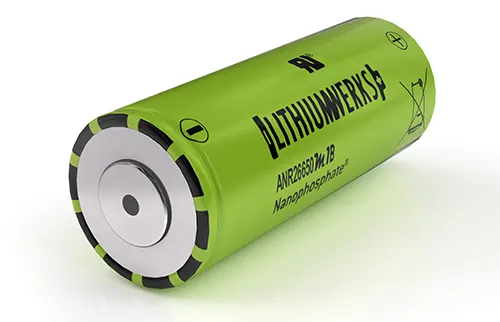
CELL: ANR26650M1-B
The LithiumWerks ANR26650M1-B is the next generation of A123 Systems’ pioneering 26650 cylindrical cells, now with greater power and energy density and lower impedance. This versatile lithium-ion cell is suitable for a wide variety of applications and system designs. Proven performance in the toughest conditions, combining durability, reliability, and safety, the ANR26650 cell offers an excellent combination of price-performance.
INTRODUCTION:
Lithium 26650 cells are capable of delivering very high power due to their use of
patented Nanophosphate battery technology. Based on lithium iron phosphate chemistry
(LiFePO4), the cells are inherently safe over a wide range of temperatures and conditions.
Whether the application requires outstanding cycle life or stable float reliability, the Lithium
Werks’ 26650 cells are suitable for a wide variety of power, pulse, or stand-by applications.
Components of the battery pack:
- Cells (Different form factors & chemistry types)
- BMS (Electronics to manage the battery)
- Connection System (Connector, pigtail, wires)
- Housing (Plastic, sheet metal, shrink, etc.)
Cells:
A pack can contain one cell or many cells configured to achieve higher capacity or output voltage. This is achieved by connecting cells in parallel or series, and we'll explore this much further in our next blog. The cell is considered the “fuel tank” of the battery pack system, holding the energy that will be released during discharge (when the engine is running) or replaced during a charge cycle (when the tank is refilled at a gas station). However, there are other components needed to utilize the energy stored in the cell.
BMS:
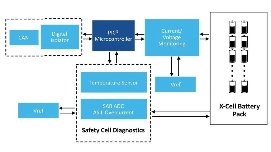
The BMS is the control system of the pack and can be simple or complex, depending on the need of the battery pack and host application. Returning to the car analogy, think of a battery pack's BMS as a car's control system. In a car, the control system shuttles fuel from the fuel tank to the engine to be utilized in a controlled and safe manner and notifies the user of any issues (i.e. low fuel). The BMS performs a similar role by safely regulating the energy carried through the cells inside a battery pack. It can also communicate information back to the end-user (i.e. low battery life).
Connection System:
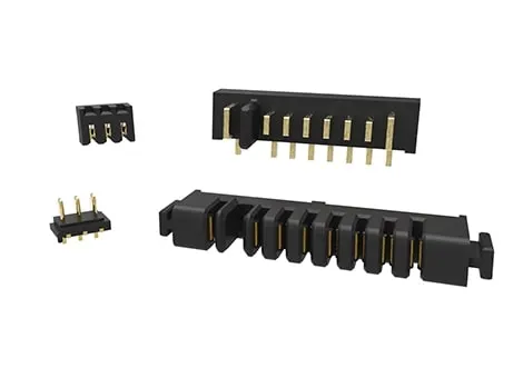
The connection system is what transforms a cell into a battery pack. There must be a connection between the cell and the BMS in order to interface with each other. Nickel strips are the preferred method of connecting a battery cell to the control system. A thin strip of nickel is capable of carrying high amounts of current, is flexible, durable, and can be attached to the cell without the use of excessive heat. These strips provide a safe means of getting the "fuel" out of the "fuel tank" to use it in a safe manner.
Housing:
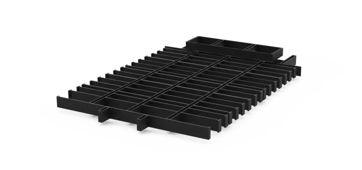
Lastly, all these components need to be packaged so that the battery pack can be installed into a device. Once all components are properly placed and connected to one another, they are sealed with either shrink wrap or a hard case. The housing ensures that the components remain safely located and provides a clean package for eventual use by an end-user. The type of housing depends on where the battery pack will be located inside the device and if it is intended to be accessed by the end-user or a technician.
Thermal management:
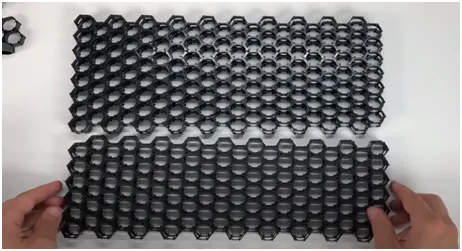
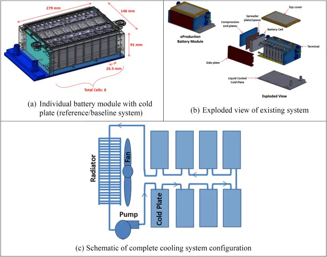
Thermal management is a major issue in high-power designs, particularly for automotive applications. As part of the battery system, it may be necessary to provide air or water cooling ducts, pumps or fans, and heat exchangers for high-temperature working or heaters for operating in low-temperature environments. The layout of the cells should be conducive to managing heat flows within the pack.
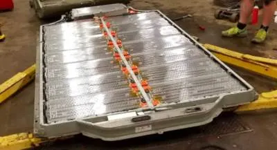
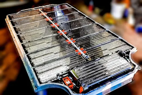
COMPLETE BATTERY PACK
PLOT CELL BEHAVIOUR
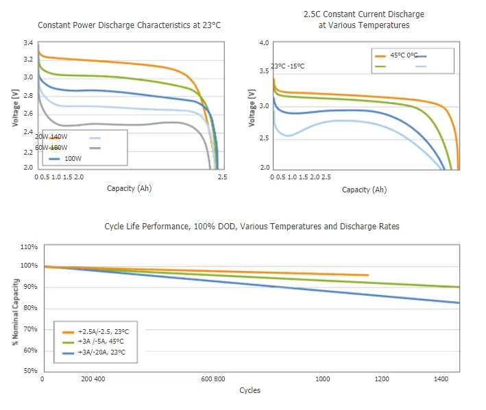
ANR26650M1-B Specifications
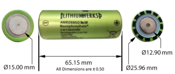
Nominal Ratings
Voltage: 3.3 Volts
Capacity: 2.5 Ah
Energy: 8.25 Wh
Specific Power: 2600 W/kg
Impedance (1KHz AC Typical) 6 mΩ
Cycle Life at 1C/1C, 100% DOD: > 4000 cycles
Cell Type: 26650 Lithium Ion Power Cylindrical Cell
Discharging
Max Continuous Discharge: 50 A
Max Pulse Discharge Current >50% SOC (10s): 120 A
Minimum Voltage: 2 Volts
Temperature: -30ºC to 55ºC
Charging
Recommended Standard Charge: 2.5 Amps
Max Charge Rate: 10 Amps
Max Pulse Charge Current <50% SOC (10s): 25 A
Float Voltage: 3.45 Volts
Recommended charge V & Cut-off Current: 3.6 Volts, taper to 125mA
Temperature
(reduce charging current to 250mA when under 0ºC): 0ºC to 55ºC
Mechanical
Diameter: Ø25.96 +/- 0.5 mm (1.0")
Length: 65.15 +/- 0.5 mm (2.6")
Mass: 76 g
Cylindrical Cell Primary Applications:
- Portable high-power devices
- Stationary battery backup systems
- Grid stabilization energy storage systems
- Commercial truck and bus hybrid electric vehicles (HEVs)
Lithium-Ion Cell Benefits:
- Power: Over 2,600 W/kg and 5,800 W/L
- Safety: Excellent abuse tolerance and environmentally friendly
- Life: Excellent calendar life, 10X cycle life vs. conventional lithium-ion
Cell calculation:
Cell volume = π⋅r2⋅hπ⋅r2⋅h
= 3.14⋅(0.013)2⋅0.0653.14⋅(0.013)2⋅0.065
= 0.000034m30.000034m3
Cell energy = Nominal voltage * Nominal cell capacity
= 3.3*2.5
= 8.25 Wh
Cell energy density = cell energy/cell volume
= 8.25/0.00034
= 24.3 kWh/m^3
Battery pack assumptions:
- There will 46 cells in series and 48 cells in parallel.
- So the pack will be 46S48P.
- All cells will be of ANR26650M1-B type.
Battery pack calculations:
Total number of cells = Cells in series * cells in parallel
= 46*48
= 2208 cells
Voltage = Nominal cell voltage * number of cells in series
= 3.3*46
= 151.8V
Capacity = Nominal cell capacity * number of cell in parallel
= 2.5*48
= 120Ah
Energy = Voltage * Capacity
= 151.8*120
= 18216 Wh
= 18.216kWh
Volume = Cell volume * Total number of cells
= 0.000034 * 2208
= 0.075m^3
Energy density = Battery pack energy/Volume
= 18.216/0.075
= 242.88 kWh/m^3
Weight = Total number of cells * Cell weight
= 2208*76
= 167.808 Kg
BATTERY PACK ASSEMBLY
In order to engineer a battery pack, it is important to understand the fundamental building blocks, including the battery cell manufacturing process. This will allow you to understand some of the limitations of the cells and the differences between batches of cells. Or at least understand where these may arise.
Step 1 – Mixing
The anode and cathode materials are mixed just prior to being delivered to the coating machine. This mixing process takes time to ensure the homogeneity of the slurry.
Cathode: active material (eg NMC622), polymer binder (e.g. PVdF), solvent (e.g. NMP), and conductive additives (e.g. carbon) are batch mixed.
Anode: active material (eg graphite), a conductive material (eg carbon black), and polymer binder (eg carboxymethyl cellulose, CMC)
N-Methyl-2-pyrrolidone (NMP): this is a toxic substance, widely used in the plastics industry as it is nonvolatile and able to dissolve a wide range of materials.
Challenges
- Homogeneity of the mix
- No breakup of the particles
- Moving from a batch mixing process to continuous mixing
Step 2 – Coating
The anode and cathodes are coated separately in a continuous coating process. The cathode (metal oxide for a lithium-ion cell) is coated onto an aluminum electrode. The polymer binder adheres to anode and cathode coatings to the copper and aluminum electrodes respectively.
Challenges
- Control thickness
Step 3 – Drying
Immediately after coating the electrodes are dried. This is done with infrared heating on a continuous process. The solvents are recovered from this process.
Challenges
- Recovering solvent
- Avoiding cracking
Step 4 – Calendering
This is a rolling of the electrodes to a controlled thickness and porosity.
Challenges
- Controlling uniform thickness
- Avoiding cracking
Step 5 – Slitting
The electrodes up to this point will be in standard widths up to 1.5m. This stage runs along the length of the electrodes and cuts them down in width to match one of the final dimensions required for the cell.
It is really important that no burrs are created on the edges of the electrodes during this process as they can cause damage to the separator and a possible short-circuit at a later date.
Challenges
- Avoiding burrs on edges
- Ensuring no loose metallic particles contaminate coatings
Step 6 – Final Drying
The electrodes are dried again to remove all solvent content prior to the final processes before assembling the cell.
Step 7 – Cutting
The final shape of the electrode including tags for the electrodes is cut. At this point, you will have electrodes that are exactly the correct shape for the final cell assembly.
Challenges
- Avoiding burrs on edges
- Ensuring no loose metallic particles contaminate coatings

Step 8 – Winding or Stacking
In a cylindrical cell the anode, cathode, and separator are wound into a spiral. For pouch cells, the electrodes stacked: anode, separator, cathode, separator, anode, separator, etc.
Some prismatic cells have stacked electrodes and some have a flat wound jelly roll.
Challenges
- Alignment of layers
Step 9 – Terminal Welding
The anodes are connected to the negative terminal and the cathodes to the positive terminal. The process and robustness of this joint are important to understand as welding the cell to busbars can damage the internal welds.
Challenges
- Ensuring no sputter contaminates cell
- Ensuring good consistent electrical connections
Step 10 – Canning or Enclosing
The electrodes either as a roll or pack of stacked layers are loaded into the can. Depending on the cell format will change how this canning or enclosing process is completed.
Challenges
- Ensuring no debris in the can
- Ensuring no damage to jelly roll or stack
Step 11 – Filling
The up-until now dry cell is now filled with electrolytes. A partial vacuum is created in the cell and a pre-determined quantity of electrolytes is delivered to the cell. The partial vacuum helps the distribution and hence wetting of all layers within the cell.
The electrolyte is dispensed based on a defined volume of liquid. A second quality check is the weight of the cell before and immediately after filling.
Challenges
- Wetting of all layers within the jelly roll or stack with electrolyte
Step 12 – Formation & Sealing
The cell is charged and at this point gases form in the cell. The gases are released before the cell is finally sealed. The formation process along with the aging process can take up to 3 weeks to complete.
During the formation process, a solid-electrolyte interface (SEI) develops. The SEI can prevent the irreversible consumption of electrolytes and protect the anode from overpotential during fast charging.
Challenges
- Checking cell is sealed
- Running formation cycle without damaging the cell
Step 13 – Ageing
The cells are stored at a controlled temperature for a period of time. This allows the SEI to stabilize.
This step in the process ties up the cells for a length of time, this inventory of cells has a considerable value and hence ties up funds.
Challenges
- Forming and aging the cell fast and delivering quality working cells
- Fire detection in the aging storage system
- Reducing time for aging and so reducing the inventory of cells
Step 14 Final Control Checks
Alongside the charge/discharge cycle data, a visual inspection is often carried out to check the integrity of the cell post cycling and prior to dispatch. All data is recorded against the cell's unique identification.
This is a first overview of the battery cell manufacturing process. Each step will be analyzed in more detail as we build the depth of knowledge.
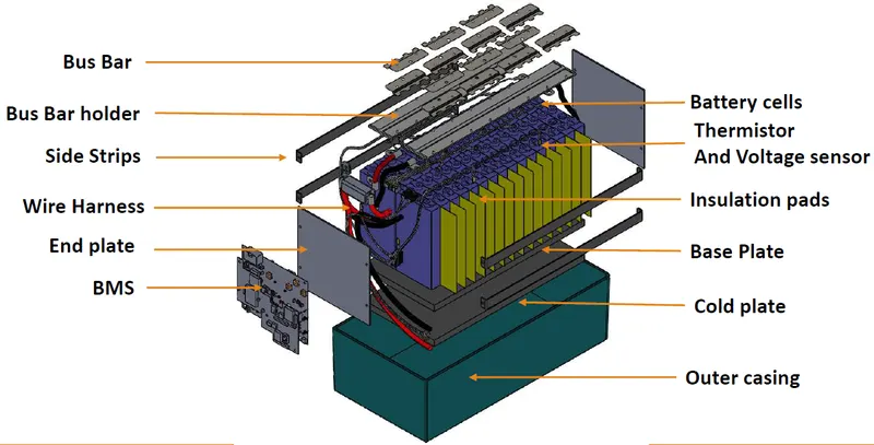
CONCLUSION: Successfully, designed and calculations of the mechanical battery pack of 18kwh capacity.