Project 1 Mechanical design of battery pack
Battery pack capacity: 18 kWh
Cell: ANR26650M1-B
Prepare a detailed battery pack drawing along with its enclosure. State your assumptions.
According to requirement of battery pack capacity with existing given cell we need to first calculate how many cells we require and how to connect them to get desire output.
Cell: ANR26650M1-B
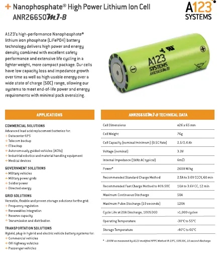
Cell Parameter :-
Dimesnion - Ø26 × 65mm
Weight - 76gm
Cell Capacity - 2.4Ah
Nominal Voltage - 3.3V
From above data first calculate power capacity of particular cell.
Power of one cell = Cell capacity × Nominal Voltage
= 2.4 × 3.3
= 7.92 Wh
Total cell reuire to get 18kWh power,
Number of cell require = 18000 / 7.92
= 2273 NOS
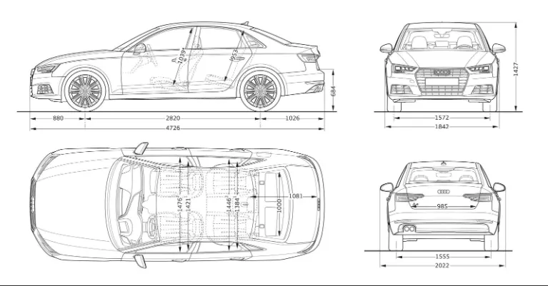
Now assume that we are designing battery pack for Audi A4 car. So car require 300V for battery pack. And car basic dimensions are 4726mm in length and 1842mm in width. As specially cabinate area space is 2820mm in length and 1476mm in width. So, we assume to install battery pack below passanger cabinate.
First of all focus to get 300V of battery pack,
Requirement of no. of cell to connect in series to get 300V = Required Voltage / One cell Nominal Voltage
= 300/3.3
= 91 NOS
So, according to that we have to make 1 module contain 91 NOS cell in parallel conncetion. Now, number of module require to get desire battery pack capacity,
Capacity of one module of parallel connected cell = 91 × 7.92
= 720.72 Wh
No. of module requirement = Total required capacity / One module capacity
= 18000/720.72
= 24.92 Approx. 25 NOS
Now cell pack is defined with 91S25P connection.
Battery Pack data :-
Total Cells - 2275 NOS
Total Pack capacity - 18018Wh = 18.018kWh
Pack ampere - 60A
Pack dimension - 2366 × 60 × 65 mm
Weight of pack because of cell - 172.9 Kg
This battery is easily fit beow passenger cabinate because it has less dimension then passanger cabinate.
Manufacturing of Battery Pack :-
First of all looking for cell manufacturing processes.
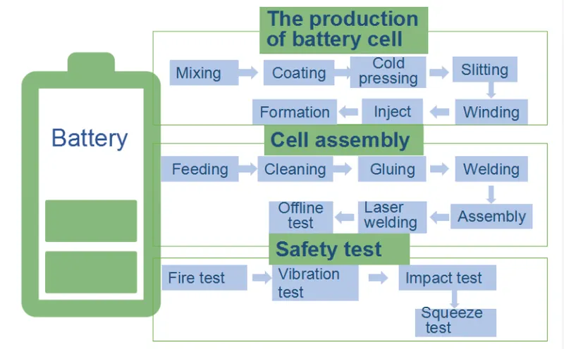
Process Dicription :-
Step 1 – Mixing
The anode and cathode materials are mixed just prior to being delivered to the coating machine. This mixing process takes time to ensure the homogeneity of the slurry.
Cathode: active material (eg NMC622), polymer binder (e.g. PVdF), solvent (e.g. NMP) and conductive additives (e.g. carbon) are batch mixed.
Anode: active material (eg graphite), conductive material (eg carbon black), and polymer binder (eg carboxymethyl cellulose, CMC)
N-Methyl-2-pyrrolidone (NMP): this is a toxic substance, widely used in the plastics industry as it is nonvolatile and able to dissolve a wide range of materials.
Challenges
- Homogeneity of the mix
- No breakup of the particles
- Moving from a batch mixing process to continuous mixing
Step 2 – Coating
The anode and cathodes are coated separately in a continuous coating process. The cathode (metal oxide for a lithium ion cell) is coated onto an aluminium electrode. The polymer binder adheres anode and cathode coatings to the copper and aluminium electrodes respectively.
Challenges
- Control thickness
Step 3 – Drying
Immediately after coating the electrodes are dried. This is done with infrared heating on a continuous process. The solvents are recovered from this process.
Challenges
- Recovering solvent
- Avoiding cracking
Step 4 – Calendering
This is a rolling of the electrodes to a controlled thickness and porosity.
Challenges
- Controlling uniform thickness
- Avoiding cracking
Step 5 – Slitting
The electrodes up to this point will be in standard widths up to 1.5m. This stage runs along the length of the electrodes and cuts them down in width to match one of the final dimensions required for the cell.
It is really important that no burrs are created on the edges of the electrodes during this process as they can cause damage to the separator and a possible short-circuit at a later date.
Challenges
- Avoiding burrs on edges
- Ensuring no loose metallic particles contaminate coatings
Step 6 – Final Drying
The electrodes are dried again to remove all solvent content prior to the final processes before assembling the cell.
Step 7 – Cutting
The final shape of the electrode including tags for the electrodes are cut. At this point you will have electrodes that are exactly the correct shape for the final cell assembly.
Challenges
- Avoiding burrs on edges
- Ensuring no loose metallic particles contaminate coatings
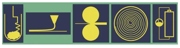
Step 8 – Winding or Stacking
In a cylindrical cell the anode, cathode and separator are wound into a spiral. For pouch cells the electrodes stacked: anode, separator, cathode, separator, anode, separator etc.
Some prismatic cells have stacked electrodes and some have a flat wound jelly roll.
Challenges
- Alignment of layers
Step 9 – Terminal Welding
The anodes are connected to the negative terminal and the cathodes to the positive terminal. The process and robustness of this joint are important to understand as welding the cell to busbars can damage the internal welds.
Challenges
- Ensuring no sputter contaminates cell
- Ensuring good consistent electrical connections
Step 10 – Canning or Enclosing
The electrodes either as a roll or pack of stacked layers are loaded into the can. Depending on the cell format will change how this canning or enclosing process is completed.
Challenges
- Ensuring no debris in can
- Ensuring no damage to jelly roll or stack
Step 11 – Filling
The up until now dry cell is now filled with electrolyte. A partial vacuum is created in the cell and a pre-determined quantity of electrolyte is delivered to the cell. The partial vacuum helps the distribution and hence wetting of all layers within the cell.
The electrolyte is dispensed based on a defined volume of liquid. A second quality check is the weight of the cell before and immediately after filling.
Challenges
- Wetting of all layers within the jelly roll or stack with electrolyte
Step 12 – Formation & Sealing
The cell is charged and at this point gases form in the cell. The gases are released before the cell is finally sealed. The formation process along with the ageing process can take up to 3 weeks to complete.
During the formation process a solid-electrolyte interface (SEI) develops. The SEI can prevent the irreversible consumption of electrolyte and protect the anode from overpotential during fast charging.
Challenges
- Checking cell is sealed
- Running formation cycle without damaging the cell
Step 13 – Ageing
The cells are stored at a controlled temperature for a period of time. This allows the SEI to stabilize.
This step in the process ties up the cells for a length of time, this inventory of cells has a considerable value and hence ties up funds.
Challenges
- Forming and ageing the cell fast and delivering quality working cells
- Fire detection in ageing storage system
- Reducing time for ageing and so reducing inventory of cells
Step 14 Final Control Checks
Alongside the charge/discharge cycle data, a visual inspection is often carried out to check the integrity of the cell post cycling and prior to dispatch. All data is recorded against the cells unique identification.
This is a first overview of the battery cell manufacturing process. Each step will be analysed in more detail as we build the depth of knowledge.
Now cell is ready to use for making battery pack.
Battery Pack :-
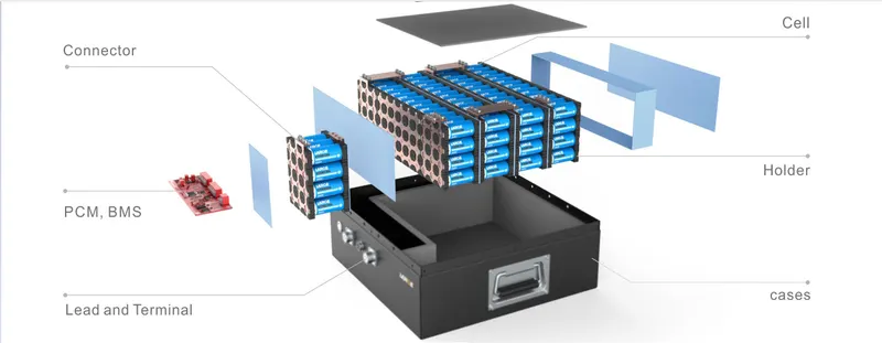
Battery pack mainly contains four major components rather than cell,
(1) Cell holder
(2) Nickel Strip used to connect cell in series and parallel
(3) BMS
(4) Cooling System
1. Cell Holder :-
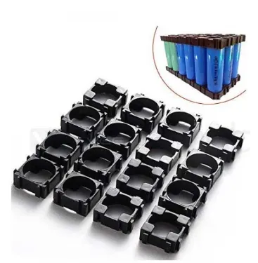
- Connecting plates of a sufficiently large thickness can be respectively connected to terminals attached to positive and negative sides, respectively, thereby providing a cylindrical cell which is suitable for supplying a large current and a cell pack using the cylindrical cell.
- A cell holder is provided in which upper and lower end portions of cylindrical cells are held by a pair of supporting members provided with a vent hole, thereby allowing heat generated from the cylindrical cells to be dissipated to the exterior via the vent hole.
- In order to attain the objects, in a cylindrical cell, terminals are attached to the cover on the positive side and the bottom face of the case on the negative side, respectively. Each of the terminals consists of a face portion in which a female threaded hole is opened or a male threaded portion is erected, and legs which are formed by bending the four sides of the face portion. The legs are spot-welded to the cover and the bottom face of the case. A connecting member of a sufficiently large thickness is screwed by a bolt to the terminals. A part or whole of the connecting member is configured by a flexible material.
2. Joining Nickel Strip :-
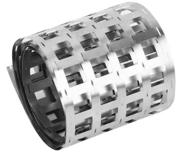
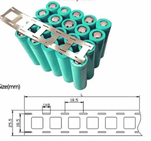
- A cell connection strap for electrically connecting a pair of adjacent battery cells within a battery pack includes, in one example, a fusible link for preventing a thermal runaway condition from occurring in a cell connected thereto. The strap may include raised features thereon for permitting relative movement between the cells in the pack due to vibration or an impact of the pack from translating stress to welds connecting the straps to the cells. In another example, the body of the cell strap may include slits formed in sides thereof to reduce rigidity of the strap for protecting the welds between strap and cell, and also provides a fusible link capability in the strap for preventing a thermal runaway condition from occurring in a cell connected thereto.
-
Battery Connection Welding metal Strip with 99.96% Pure Nickel -10Pcs. made of Pure Nickel Plate with 99.96% Pure Nickel Strap Strips Sheets.
-
It is generally useful in the welding of battery points together to connect the batteries in combinations. These Nickel strips are popular because of their good performance while soldering as it gets soldered very quickly; easily with normal soldering metal with High tensile tension and Low resistivity.
3. BMS :-
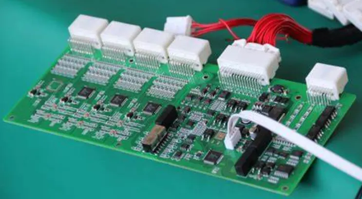
- BMS is short for Battery Management Systems, which is an electronic system for the rechargeable battery so as to prevent the battery from hazard when the battery goes beyond the minimum or maximum SOC (state-of-charge) limit as well as the charge and discharge cycles. It monitors the battery state, calculates and reports the secondary data, and controls the battery working environment by authenticating and balancing it. It is usually related with PCM which is the acronym for protection circuit module, but have more protection and features.
-
BMS is comprised of several functional blocks which can be divided into main parts of cutoff FETs, a fuel gauge monitor, a state machine, cell voltage monitor, cell voltage balance, temperature monitors, and other blocks including real-time clock (RTC), battery authentication block, voltage reference and daisy chain circuitry.
- The monitoring of each cells’ voltage is vital for the overall battery health, and BMS for lithium ion battery usually has an operating voltage window for every cells when charging and discharging to avoid fast degradation.
4. Cooling System or Thermal Management System :-
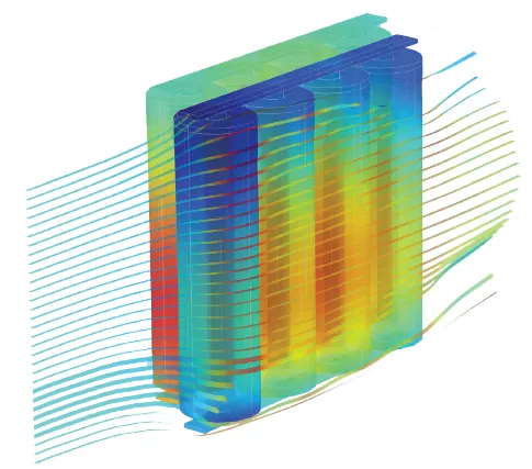
- While advancements have been made in electric vehicle batteries that allow them to deliver more power and require less frequent charges, one of the biggest challenges that remain for battery safety is the ability to design an effective cooling system.
- In Electric cars, discharging the battery generate heat, the more rapidly discharge battery the more heat generated.
- Batteries work based on the principle of a voltage differential, and at high temperatures, the electrons inside become excited which decreases the difference in voltage between the two sides of the battery. Because batteries are only manufactured to work between certain temperature extremes, they will stop working if there is no cooling system to keep it in a working range. Cooling systems need to be able to keep the battery pack in the temperature range of about 20-40 degrees Celsius, as well as keep the temperature difference within the battery pack to a minimum (no more than 5 degrees Celsius).
- If there is a large internal temprature difference, it can lead to different charge and discharge rate for each cell and deteriorate the battery pack performance.
- Potential thermal stability issues, such as capacity degradation, thermal runaway, and fire explosion, could occur if the battery overheats or if there is non-uniform temperature distribution in the battery pack. In the face of life-threatening safety issues, innovation is continually happening in the electric vehicle industry to improve the battery cooling system.
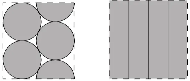
- Generally this kind of arrangement has void inbetween so we are generally using air cooling system for Cylindrical cell battery pack.
Battery Pack Example :-
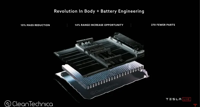
So, this is how we claculate battery pack according to our requirement and also these manufacturing processes used to make battery pack.