Project 1 Mechanical design of battery pack
In order to design a battery pack of 18kwh lets understand first the fundamentals of lithium ion battery.
The smallest unit of a battery is called a cell. A cell is composed of an anode (-), a cathode (+) and is able to receive, store and provide electric energy. Cells are arranged in series or paralel to formbattery pack
Cells have different characteristic voltages depending of its chemistry. This voltage is the nominal voltage and the cell can produce higher or lower voltage depending of the state of charge. Most lithium ion batteries have its nominal voltage above 3.0 V.
One of the most important fucntions of a battery is to store energy and charge. Charge capacity is the charge a cell is able to store. Its units are Ah (or in IS, Coulomb – 1Ah = 3600 C). Similarly to the voltage characteristics, different chemistries have different capacities.
The energy a cell is able to store is know as energy capacity, or nominal energy capacity. Its units are Wh (Watt * hour) or J (Joules).
The discharge or charge rates of the cell are know as C-rate.
This is the theoretical charge that the cell can supply for 1h. For example, a 3Ah battery is able to supply 3A for 1 hour. This would be called 1C discharge rate. At 2C, it will supply 6A for 30 min.
A lithium ion battery with cells of 36V and 2Ah, has roughly 72 Wh energy storage capacity. The power at which the battery can be discharged is a relationship of its internal resistance and is difficult to quantify
this means if we have 10 lithium ion cells of 2Ah and 3.6 V connected in series, the battery will have a charge capacity of 2Ah and an energy storage capacity of 72 Wh, and a voltage of 36V. If the same cells are connected in paralel, the voltage of the battery will be 3.6V, a charge capacity of 20Ah and an energy storage capacity of 72 Wh.
The energy density is the energy capacity of the battery per unit mass or volume. This gives an indication for comparison of how small a battery can be packaged to achieve the same energy capacity.
Introduction to lithium ion battery
- Lithium ion cells operate at higher voltages (3.7V nominal voltage) than other common chemistries (e.g. 1,2V for NiMH). This makes them suitable for more applications since less cells are required to achieve a given voltage.
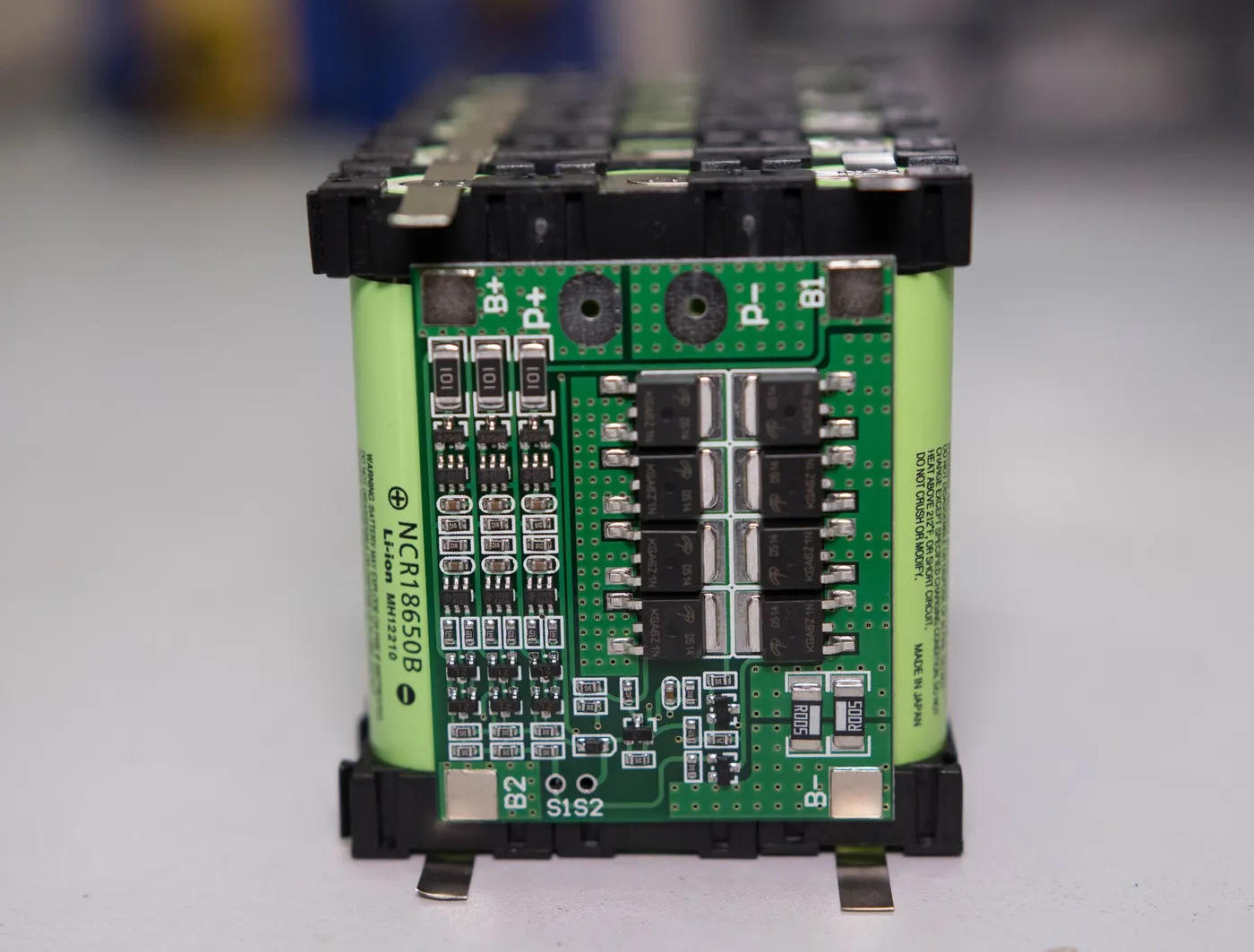
- Although other cell chemistries do not require a BMS, lithium ion cells need it to operate within safety conditions. In practical terms, a BMS is a piece of electronic circuitry that measures voltage and other parameters of all or a number of cells in the battery. An algorithm in the electronic device determines whether the voltage of a particular cell needs to be adjusted which is actioned by the same device. The fact that lithium ion cells need a BMS, is a small drawback compared to other chemistries, However, for high performance or large capacity applicaions, all chemistries need a BMS, hence this is no longer a negative
- Lithium ion cells have lower self-discharge rate than other chemistries. Even after months of built date, Li-ion cells will retain most of its capacity. Compared to other chemistries such as NiMH or NiCd where the self discharge rate is in the region of 1%5% this is a big advantadge.
- There are standard cell sizes (AA, C, D) for other chemistries that do not apply to lithium ion cells. Instead, common li-ion cell types are “18650” or “26650” that define its form factor. For instance, a 18650 means the cell is 18 mm in diameter and 65 mm in length.
CELL CHEMISTRY:
Lithium ion batteries have a number of main chemistries used in the industry at the moment. Each chemistry offers different characteristics that make it more suitable to each application. Cell phones, laptops, power tools all use this type of chemistry. The main reason is that theyposses highest energy to weight ratio.
They have relatively long cycle life, from 300 cycles to more than 1000 cycles depending on operating conditions.
Lithium Ion cells are in the middle when it comes to cost. They are available in many different form factors and thus can be easily suited for many applications. One of the most common formats is 18650. The nominal voltage is 3.7V and voltage range is 2.5V to 4.2V.
The main types of Lithium Ion (Li-Ion) cells chemistries are:
Lithium Manganese Oxide (Li-Manganse),
Lithium Cobalt Oxide (Li-cobalt),
Lithium Polymer (Li-Po),
Lithium Nickel Manganese Cobalt Oxide (NMC),
Lithium Nickel Cobalt Aluminium Oxide (NCA or NCR)
Lithium Iron Phospate (Li-Phosphate).
Lithium Iron Phospate (Li-Phosphate).
Lithium Iron Phosphate are heavier and have lower energy density than most li-ion cells. They are also more expensive than other types, around 20% when compared with Li-ion cells of the same capacity. Their discharge rate depends vastly on the supplier, however premium makers offer high power levels which are used by OEM in automotive.
The advantadges of Lithium Iron Phosphate cells are that they are one of the most safe chemistries to operate. Fires are extremely rare due to the low oxidation reactivity of this electrolyte. Furthermore, they have large cycle life and low self discharge rate.
Lithium Iron phosphate cells have a nominal voltage of 3,2V and a range of 2,5V to 3,65V.
Cell construction
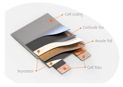
The basic manufacturing method for all lithium ion chemistries is similar. They have a cathode material as positive active material, anode material as negative active material, a membrane separating positive and negative material layers, and an electrolyte. The way those elements are packaged gives different construction formats. The main three form factor are pouch cells, prismatic cells and cylindrical cells.
Pouch cell:
Pouch cells are the simplest form of construction. The name comes from the way the active material is stored in a pouch made out of thin aluminium foil and covered by a layer of insulating material. The active materials inside are stacked in layers which determine the capacity and thermal performance. To form a battery, the pouches are stacked and clamped externally to work under pressure. This prevents the cell from expanding during operation.
Due to the thin construction they are the best volumetric efficient cells and can be the lightest depending on how the structure is completed around the stack of cells. The tabs can be both on the same side or on opposite sides
Prismatic cells:
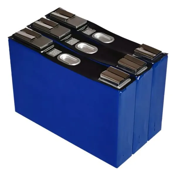
Prismatic cells are similar to pouch cells in shape. The main difference is that they have a rigid container around them. This means they are more durable than pouch cells and do not require an external clamping structure to apply pressure to the cells. The terminals usually have a boss with a threaded hole which allows a cable to be easily connected to it. These modules can be used directly for electric vehicles or house storage batteries.
Cylindrical cells
Cylindrical cells are the most common type of cells used by many consumer products. Their equivalent with lithium ion cells are for example 18650, 26650, 38120 and others depending on them manufacturer. This construction has the active material rolled inside a metallic cylindrical can that is applying pressure and provides protection. The terminals are either side of the cylinder and are usually welded to reduce electrical resistance and improve reliability.
Features of ANR26650M1B LI-ION CELL:
The ANR26650M1-B is the next generation of A123 Systems’ pioneering 26650 cylindrical cell, now with greater power and energy density and lower impedance. This versatile lithium ion cell is suitable for a wide variety of applications and system designs. Proven performance in the toughest conditions, combining durability, reliability, and safety, the ANR26650 cell offers an excellent combination of price-performance.
LithiumWerks ANR26650M1-B Specifications
Voltage: 3.3 Volts
Capacity: 2.5Ah
Dimensions
Diameter: 25.96 +/- 0.5 mm
Length: 65.15 +/- 0.5 mm
Mass: 76 g +/- 1.0 g
design of battery pack for lithium ion battery
In order to use the stored energy for vehicular application, there is the need for an inverter which converts electricity in both directions from a DC signal to AC signal. This device also receives energy from the harvesting system, usually an electric motor, back into the battery to charge it. This allows a vehicle to convert the kinetic energy into electric energy under breaking and in turn charge the battery.
DESIGNING CALCULATION OF 18KWh BATTERY PACK:
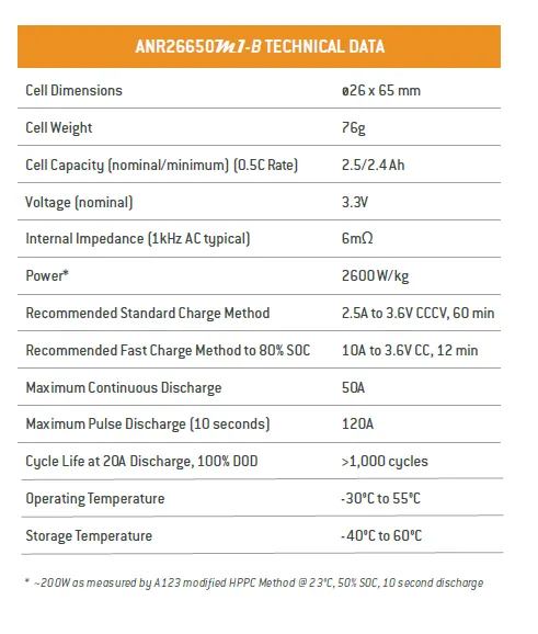
we have extracted data from ANR26650M1-B data sheet with the help of this data sheet we are going to design 18kwh battery pack.
given
battery energy=18000wh/18kwh
from data sheet
nominal voltage =3.3v
cell capacity=2.5Ah
internal impedence =5mili ohm
cell weight=76g
cell dimension=26*65mm
operating temp=-30 to 55 degree
storage temp=-40 to 60 degree
since the energy =18000wh
therefore no of cells(Ns) having energy of 18kwh=18000/(energy storage capacity)
=18000/(nominal voltage*nominal capacity)
=18000/(3.3*2.5)
Ns =2181 no of cells
to design a 18kwh battery pack we need 2181 no of cells and these cells must be connected in series and parallel connection to get the desired capacity and voltage .
what are series and parallel configuration and why we need these types of connections
A single cell is not sufficient for some devices. To achieve desired voltage, the cells are connected in series to add the voltage of cells. To achieve the desired capacity, the cells are connected in parallel to get high capacity by adding ampere-hour (Ah). This combination of cells is called a battery.
Sometimes battery packs are used in both configurations together to get desired voltage and high capacity. This configuration is found in the laptop battery, which has four Li-ion cells of 3.6 V connected in series to get 14.4 V. Each cell has one another cell connected in parallel to get the double capacity of 6800mAh
In this configuration, the cells are connected in both series and parallel. The series-parallel configuration can give a desired voltage and capacity in the smallest possible size. You can see two 3.6 V 3400mAh cells connected in parallel in the image below, which doubles the current capacity from 3400mAh to 6800mAh. Because these parallel packs are connected in series, the voltage also doubles from 3.6V to 7.2 V. The total power of this pack is now 48.96Wh. This configuration is called 2SP2. If the configuration consists of eight cells with the configuration of 4SP2, two cells are in parallel and four packs of this parallel combination are connected in series. The total power produced by this pack is 97.92Wh
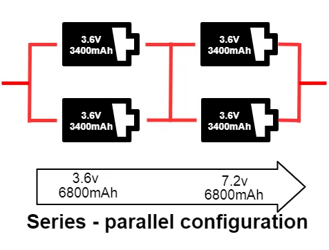
lets assume 300v are required to run the vehicle
the amp hr capacity of the battery =18kwh
nominal capacity of battery pack in amp=18000/300
=60Ah
nominal voltage of single cell=3.3v
therefore no of cells that should be connected in series to get 300 volt =assumed voltage /single cell voltage /nominal voltage
Ns =300/3.3
Ns=90.9 or 91no of cells should be connected in series
and how many no of cells should be connected in parallel(Np)=nominal capacity/single cell capacity
=60/2.5
Np =24
therefore we can say that 92 no of cells should be connected in series and 24 no of cellls connected in parallel so that we can get the 18kwh energy battery pack
hence from the above two parameters we get 91S24P configuration
in order to connect the cells in the above mentioned configuration the structure of the battery model goes very complex anddue to the complex structure fault will happens in the future and the full battery pack we get affected .to avoide this complex structure we are going to divide the battery stack into small modules
here we divide 91S24P into 7S4P
NO of cells in one module=7*4
=28
how many 7s4p modules will be required=2184/28=78 moduls
as we have already calculated battery capacity=60Ah
C rate
the battery is going to supply continuously 60Amp of current for an hour this means we are discharging the battery at 1 C rate.
Range
let the power consumption of powertrain=100w/km
from the battery pack capacity we are expecting the rane of electric vehicle =total pack capacity/power consumption /km=18000/100=180km
dimension of battery pack
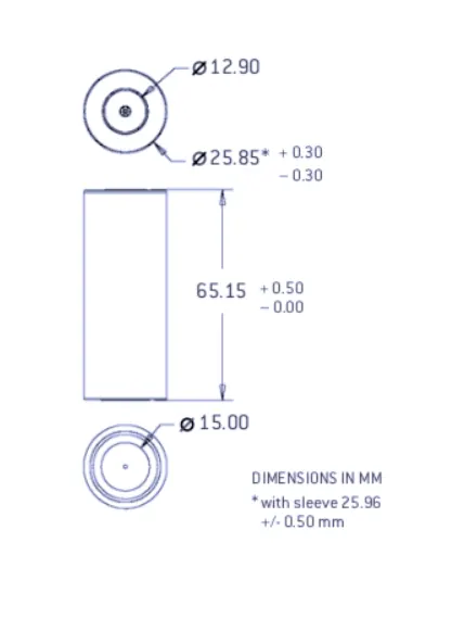
from the data sheet of ANR26650m1b
diameter of single cell=26mm
height of the cell=65mm
lets calculate dimension of battery pack
length of casing(L)=no of cells in series*[cell diameter+margin at both sides of cell]+clearance at sides
L =91*[26+4]+60
L=2790mm
L=2.79m
Width of casing(w)
w=no of cells in parallel*[cell diameter+margin at both sides of cell]+clearance at sides
w=24*[26+4]+60
w=780mm=7.8m
volume of the battery pack
single cell cylinderical volume=piR^2h
=3.14*0.013^2*0.065
=0.3452m^3
therefore we have 2181 no of cells
volume of battery pack=0.03452*2181
=75.28m^3
mass of the battery pack=no of cells in battery pack *single cell mass
=2181*0.076kg
=165.75kg
Assembely of battery pack
components that are used for assembely of battery pack
no of cells =2181
nickel strip/connecting strip
pvc heat sink film
sport welder
connectors
cell holders
soldering
cell holder
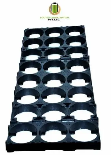
These battery holders are designed to maximize the packing density of an 18650 battery pack. That means you can fit more cells into less space, while still maintaining air gaps between cells.
The battery holders come as a group of 3. Those can then be snapped together to create larger packs. This means you can have a pack as small as 3 cells or as large as thousands of cells. Simply continue snapping together the holders to reach larger pack sizes.
insulated gaskets

Electric vehicle battery gaskets provide environmental sealing and thermal insulation. They may also provide fire protection and shielding against electromagnetic interference (EMI). EV battery gaskets are made of rubbers, or elastomers, that impart specific properties, such as chemical resistance. Because rubber is compressible, these elastomeric gaskets fill the gaps between machined metal surfaces.
nickel strip/connecting strip
once the the cells are fitted with the help of cell holders and insulated with gasket the next step is to provide cell connection for the cell connection we are going to use nickel strips
Nickel strip is generally used in battery building. Its due to its efficiency of usage in spot welding and soldering as well its high corrosion resistance over time. It has good properties and excellent resistance to many corrosive environments. The pure nickel will never get rust after it applied to battery packs. It won’t affect the current transfer between batteries.
To make the battery pack, we have to connect the 26650 cells together by means of Nickel strips or thick wire. Generally, Nickel strips are widely used for this. In general two types of nickel, strips are available in the market: nickel-plated steel strips and pure nickel strips. it has much lower resistance. Low resistance means, less heat generation during the charging and discharging, which leads to longer useful battery life.
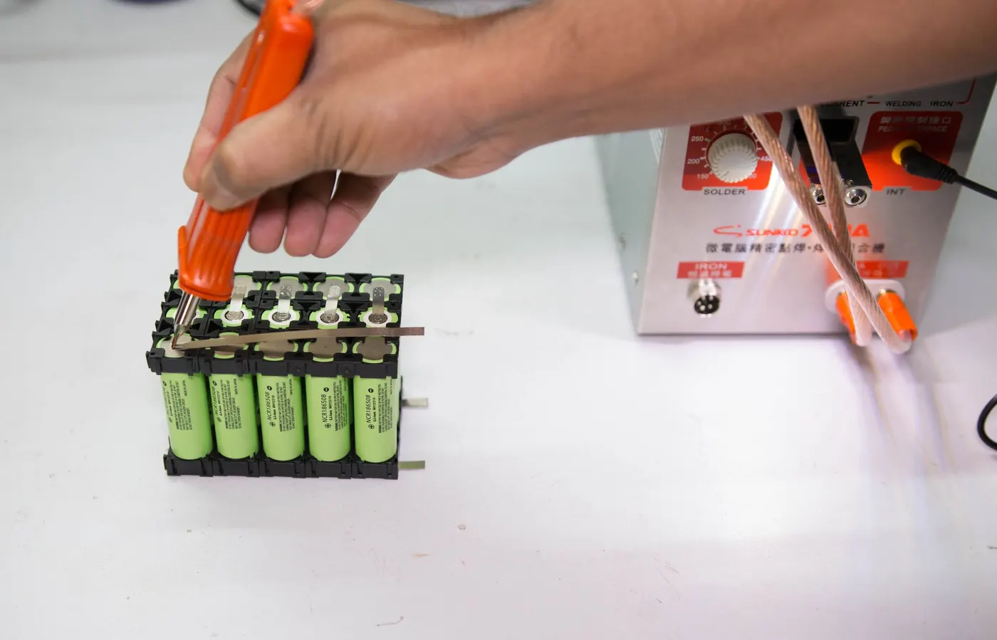
from the above image we have made connection by using pure nickel strips and join them with spot weld
from here series and parallel connections are made by connecting +ve with negative for series and +ve of once cell with +ve of next cell for parallel connections

A form of resistance welding, spot welding is one of the oldest welding processes whereby two or more sheets of metal are welded together without the use of any filler material.
The process involves applying pressure and heat to the weld area using shaped alloy copper electrodes which convey an electrical current through the weld pieces. The material melts, fusing the parts together at which point the current is turned off, pressure from the electrodes is maintained and the molten “nugget” solidifies to form the joint.
Heat sink
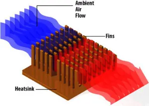
To deal with heat, batteries often include a heat sink: a conductive material (most often copper or aluminum) that carries heat away from the cell. In some cases, heat sinks employ a phase-change material that “soaks up” the heat as it melts or vaporizes,
heat is transfered from battery to sink and from sink to environment below are the process of heat flow from battery to environment
The source generates heat. This source may be any system that creates heat and requires the removal of said heat to function correctly,in our case we have to remove heat from battery
Heat transfers away from the source battery. Heat pipes can also used in this process, . In direct heat sink-contact applications, heat moves into the heat sink and away from the source via natural conduction.
Heat distributes throughout the heat sink. Heat will naturally travel through the heat sink via natural conduction moving across the thermal gradient from a high temperature to a low-temperature environment. This ultimately means that the heat sink's thermal profile will not be consistent. As such, heat sinks will often be hotter towards the source and cooler towards the sink's extremities.
Heat moves away from the heat sink. This process relies on the heat sink's temperature gradient and its working fluid―most commonly air or a non-electrically-conductive liquid. The working fluid passes across the surface of the warm heat sink and utilizes thermal diffusion and convection to remove heat away from the surface and into the ambient environment
soldering the battery wire

in last step we have to connect the battery management system in order to analyse the performance ,health charge and discharge current the battery pack and also analyse the fault in the battery pack