Project 1 Mechanical design of battery pack
Aim:
Battery pack capacity: 18 kWh
Cell: ANR26650M1-B
Objective:
Prepare a detailed battery pack drawing along with its enclosure. State your assumptions.
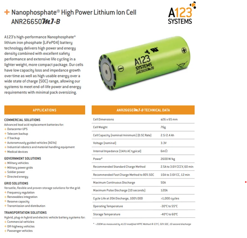
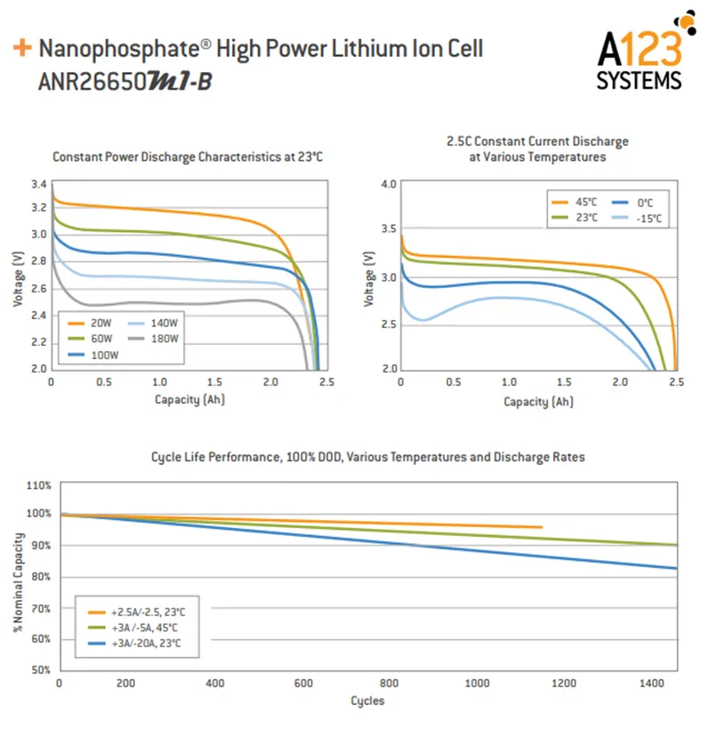
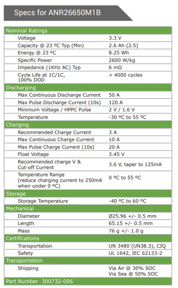
ANR26650M1-B Specifications
Nominal Ratings
Voltage: 3.3 Volts
Capacity: 2.5 Ah
Energy: 8.25 Wh
Specific Power: 2600 W/kg
Impedance (1KHz AC Typical) 6 mΩ
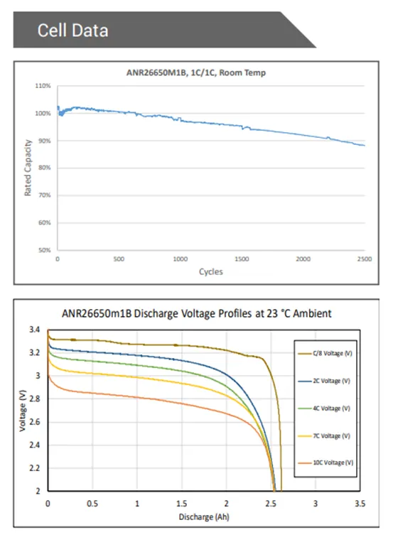
Cycle Life at 1C/1C, 100% DOD: > 4000 cycles
Cell Type: 26650 Lithium Ion Power Cylindrical Cell
Discharging
Max Continuous Discharage: 50 A
Max Pulse Discharge Current >50% SOC (10s): 120 A
Minimum Voltage: 2 Volts
Temperature: -30ºC to 55ºC
Charging
Recommended Standard Charge: 2.5 Amps
Max Charge Rate: 10 Amps
Max Pulse Charge Current <50% SOC (10s): 25 A
Float Voltage: 3.45 Volts
Recommended charge V & Cut-off Current: 3.6 Volts, taper to 125mA
Temperature
(reduce charging current to 250mA when under 0ºC): 0ºC to 55ºC
Mechanical
Diameter: Ø25.96 +/- 0.5 mm (1.0")
Length: 65.15 +/- 0.5 mm (2.6")
Mass: 76 g
Certifications
Transportation: UN 3480 (UN38.3), CIQ
Safety: UL 1642, IEC 62133
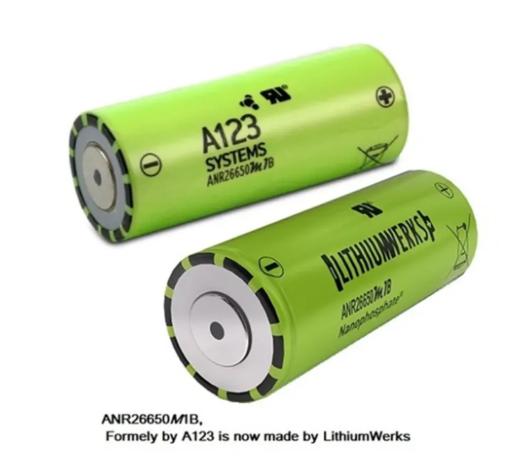
The LithiumWerks ANR26650M1-B is the next generation of A123 Systems’ pioneering 26650 cylindrical cell, now with greater power and energy density and lower impedance. This versatile lithium ion cell is suitable for a wide variety of applications and system designs. Proven performance in the toughest conditions, combining durability, reliability, and safety, the ANR26650 cell offers an excellent combination of price-performance.
Cylindrical Cell Primary Applications:
- Portable high power devices
- Stationary battery backup systems
- Grid stabilization energy storage systems
- Commercial truck and bus hybrid electric vehicles (HEVs)
Lithium Ion Cell Benefits:
- Power: Over 2,600 W/kg and 5,800 W/L
- Safety: Excellent abuse tolerance and environmentally friendly
- Life: Excellent calendar life, 10X cycle life vs. conventional lithium ion
Lithium Werks’ 26650 cells are capable of delivering very high power due to its use of patented Nanophosphate ® battery technology. Based on lithium iron phosphate chemistry (LiFePO4 ), the cells are inherently safe over a wide range of temperatures and conditions. Whether the application requires outstanding cycle life or stable float reliability, the Lithium Werks’ 26650 cells are suitable for a wide variety of power, pulse, or stand-by applications.
Nanophosphate® battery technology offers stable chemistry, faster charging, consistent output, excellent cycle life and superior cost performance. It provides the foundation for safe systems while meeting the most demanding customer requirements. Multiple layers of protection are employed at the chemistry, cell and system level to achieve an energy storage solution with superior safety and abuse tolerance compared to metal oxide lithium-ion chemistries.
Why battery Pack is Used:
Battery cells are like eggs. Cells come in fixed voltages and capacities. If you need more voltage, you can deal with multiples of the cell voltage. You can't get half an egg, and you can't get half a cell, at least in voltage. Cell capacities do vary, particularly with a supplier like PowerStream that has a great variety of cell sizes available, but voltages don't. All NiCad or NiMH cells are 1.2 volts nominal, lead acid is 2.0 volts nominal and the various lithium technologies are about 3.6 volts per cell. If you need more voltage you have to add them in series, if you need less voltage you need some kind of voltage regulator or DC/DC converter.
If you need more current than a single cell can supply you may need to put cells in parallel. If you need more capacity to give longer run time you may also put cells in parallel.
Many times the physical configuration makes it more attractive to use many small cells rather than a few large cells, since a large block is harder to fit than several small subunits.

Pack assembly:
Solder versus Weld
Most battery packs are spot welded together using nickel strip for contacts. Soldering directly to the cells is dangerous for the cells. It is easy to melt or disturb the safety vent, thwack the seals, or cause internal shorting if the heat is too high. This damage might not be noticeable until later.
However, not everyone has a capacitive discharge spot welder, so PowerStream has instituted a program where we can spot weld nickel solder tabs at the factory. This is cheap, and allows the end user to solder together custom packs easily without fear of damaging the battery.
Heat Shrink Tubing
The most common way to hold the pack together is to use heat-shrink tubing. This has sufficient strength for small packs, but as the weight increases more structural strength is necessary. This is done by adding a sheet of structural material, usually plastic or fish paper, to the top and the bottom of the pack. If the battery is to be put into another structure, either a plastic case, or the system box, it is still important to tie it together with heat shrink or tape for ease of handling.
When building and using battery packs be careful not to inadvertently short the cells. A pack of cells wired in series will become shorted if the cases of adjacent batteries touch, since the outer case is a terminal. This can happen if the cells are shrink wrapped, film wrapped or painted and the batteries rub against each other. Brittle shrink wrap is known to shred under stress, leaving the bare cell walls to touch. If there is danger of this happening cardboard sleeves are used instead of just the heat-shrink tubing.
Another source of strength is the use of glue where the cells touch. Cyanoacrylates are sometimes used to tack things together, but can weaken the vinyl heat-shrink if not reinforced. A hot-melt glue is more forgiving.
Battery Holders
When using or designing battery holders make sure there is adequate provision for short cells, long cells, or wide cells. Keep sharp clip edges from touching the cell where they could cut the film or paint, causing a short between cells held by the same clip.
Electrical and System Considerations:
How many amp-hours do I need?
Cell capacity is rated in amp-hours or milliamp hours. The symbol for capacity is C. This is amps times hours. Divide by hours and you get amps, divide by amps and you get hours. For example a 5 amp hour battery is the same as a 5000 milliamp-hour battery. If you want to discharge in 10 hours, you can get a current of 5/10 = 0.5 amps. If you need 100 milliamps current, then you can run for 5000/100 = 50 hours.
Often a discharge or charge rate is given proportional to C. So a discharge rate of C/5 means C/(5 hours), or the constant current to fully discharge the battery in 5 hours.
The calculation of run time versus current is a rough estimate, but is accurate under the right conditions. The faster you discharge, the lower the capacity of a battery. This trade-off depends on the battery chemistry and construction. Usually the capacity of a battery is quoted at a C/20 discharge rate. So an 12 amp hour battery sealed lead acid battery will actually put out a steady 0.6 amps for 20 hours. However, if you discharge the same battery at 12 amps, you would expect to run an hour, but you will only last for 22 minutes. Also, if you wan to run at 10 milliampere you will get less than the expected 1200 days, since self-discharge of the battery will limit your run time.
Different battery chemistries differ in this respect. Lead acid batteries are probably the worst at the rapid discharge end of the scale. NiCads and NiMH are much better.
How do you determine the current that your system draws?
The best way is to measure with a current meter and an adjustable power supply (usually the current meter is built into the power supply). Set the power supply to the highest voltage that the system is rated at and measure the current, then set the power supply to the lowest voltage that the system is rated at and record that current. Adding a measurement half way between the two will give you an idea of where the lowest power consumption point is (power is voltage times current). The idea is that you want to design your pack so that the voltage swing of the batteries (see below) is adequate, and where the power consumption is the least. Some systems will show approximately constant power consumption no matter what the battery voltage is, and some will have a sweet spot where the power is lowest.
If a variable power supply is not available, chart the current versus the voltage of the battery during a discharge cycle.
If making actual measurements is not possible, use the system data sheet, or the "boilerplate" sticker on the back to find the rated wattage or input current. This will usually give you a high estimate, or a peak value.
Batteries in Series and Parallel.
With NiCad and NiMH cells are best used in series, not in parallel. This is because keeping the battery pack equally yoked during repeated charge and discharge conditions can be a problem. So a good approach is to choose the cells that will give you the capacity and current that you need and put them in series to get the voltage you need.
With lead acid and lithium batteries parallel and even series + parallel packs are common.
Series
When used in series, the voltage is multiplied but the amp-hours stays the same. So three 5AH 3.6V in series would give a 5AH 10.8V pack.
Parallel
When used in parallel the voltage stays the same and the amp-hours multiply. So three 5AH 3.6V cells in parallel would give a pack that is 15AH and 3.6V.
The first question to answer is "how much voltage do I need?" The second is "how many cells in series do I need?"
The voltage of any cell is a moving target. When fully charged the voltage will be higher than nominal, and at the end of capacity the voltage will be lower than nominal. The following table shows the range of the various chemistries:
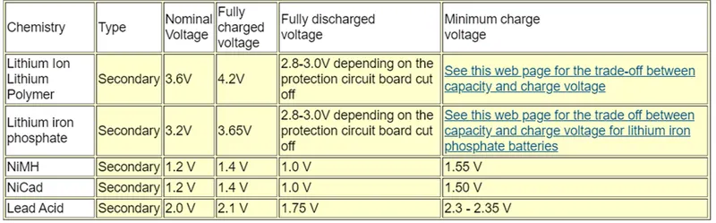
So a 10 cell pack of NiMH cells would have 14 Volts when fully charged, and run down to 10 volts when fully discharged. Your system must be able to tolerate this voltage range.
Furthermore, if you want to be able to charge while your system is running, the system must be able to accept the charging voltage, which is always higher than the nominal or the fully charged voltage. Work with the charger manufacturer to make sure that you have this problem solved.
Resistance of the Nickel Strip in Battery Assembly
Nickel foil is used to spot weld packs together. Nickel is fairly low resistance, yet has enough resistivity to be spot welded. It is strong, has very good corrosion resistance, and will not oxidize easily.
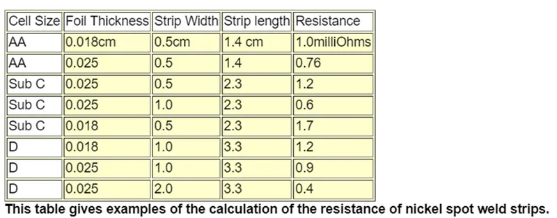
The resistivity of nickel is 6.9 x 10⁻⁶Ohm-cm. The formula to be used to calculate the resistance for a nickel strip is R = { L / ( w*t } rho, where L is the length of the strip, w is the width, and t is the thickness, all in cm. The length L can be estimated as the diameter of the cells. The following table gives typical values. This is a conservative estimate, since in many cases the spot welds are closer to the edge of the than we have assumed.
References:
https://www.powerstream.com/BPD.htm
https://www.instructables.com/DIY-Professional-18650-Battery-Pack/