Project 1 Mechanical design of battery pack
AIM:
To prepare a detailed battery pack drawing along with its enclosure, and its assumptions.
EXPLANATION:
lithium iron phosphate (LiFePO4) battery technology delivers high power and energy density combined with excellent safety performance and extensive life cycling in a lighter weight, more compact package. Our cells have a low capacity loss and impedance growth over time as well as high usable energy over a wide state of charge (SOC) range, allowing our systems to meet end-of-life power and energy requirements with minimal pack oversizing.
BATTERY PACK CAPACITY: 18 kWh
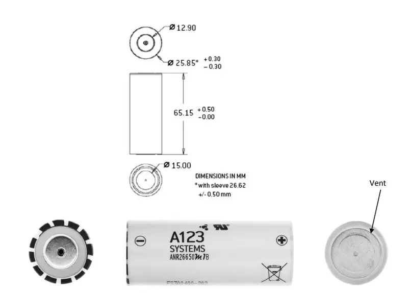
CELL: ANR26650M1-B
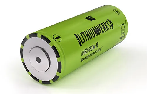
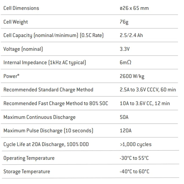
CELL SPECIFICATIONS: (ANR26650M1-B)
| Nominal Voltage | 3.3V |
| Nominal Capacity | 2.5Ah |
| Maximum discharge current - continuous (A) |
70A, with the caveat, that the cells do NOT exceed their maximum operating temperature (+60°C) |
| Pulse discharge at 10 sec | 120A |
| Peak power @ 10 s (watts) | 210W |
| Recommended standard charge | 1.5C to 3.6 V |
| Recommended fast charge | 4C to 3.5V |
| Recommended float charge voltage | 3.5V |
| Recommended end of discharge cutoff |
2.0V |
| Operating Temp Range | -30°C to +60°C |
| Storage temperature range | -40°C to +60°C |
| Weight | 75 grams |
APPLICATIONS:
COMMERCIAL;
Advanced lead-acid replacement batteries for:
1) Datacenter UPS
2) Telecom backup
3) IT backup
4) Autonomously guided vehicles (AGVs)
5) Industrial robotics and material handling equipment
GOVERNMENT;
1)Military vehicles
2) Military power grids
3)Soldier power
4)Directed energy
GRID SOLUTIONS;
1) Frequency regulation
2) Renewables integration
3) Reserve capacity
4) Transmission and distribution
TRANSPORTATION SOLUTIONS:
Hybrid, plug-in hybrid, and electric vehicle battery systems for:
1) Commercial vehicles
2) Off-highway vehicles
3) Passenger vehicles
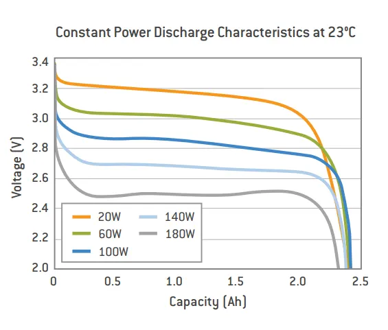
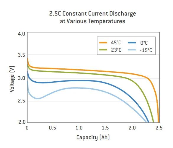
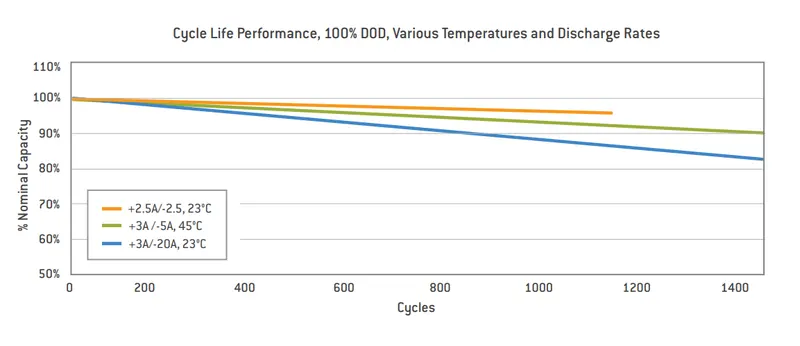
DISCHARGE CHARACTERISTICS:
SYSTEMS:
MECHANICAL DESIGN:
Basic Pack Design
This chapter includes the following sections:
• Overview
• Mechanical Connection and Protection
• Thermal Management
OVERVIEW:
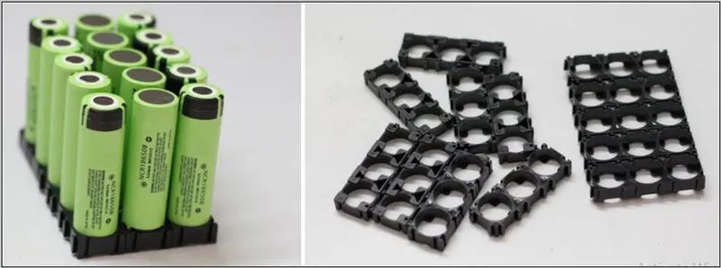
Battery Packs (also known as Energy Storage Systems (ESS) and battery modules)should be designed to protect and replicate the individual cell performance of multiple cells in the pack. This means providing mechanical protection and integrity, thermal stability, and electrical protection and performance.
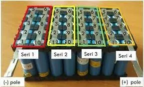
MODULE ARRANGEMENT:
MECHANICAL AND PROTECTION:
Design mechanical interconnects to prevent accidental short circuits. Size these mechanical interconnects to carry the expected maximum rated current for both the maximum time and ambient temperature in which the pack is expected to operate.
CELL INTERCONNECTS:
Size cell interconnects for the expected maximum current carrying capability. Improperly sized tabs could heat up excessively, resulting in even higher resistivity. For reliable welded connections at the terminals, In addition, other alloys afford both weldability, strength, and low resistance, which are all desirable features of a good interconnection. Cellinterconnects (tabs) should be neither soldered on the end caps nor attached using extreme heat. recommends tabs be resistant or laser-welded to both ends of the cells. Resistance welding provides a constant current for a specified period of time through a salient feature in the weld tab. These parameters can be specified and regulated for a consistent high-quality weld every time.
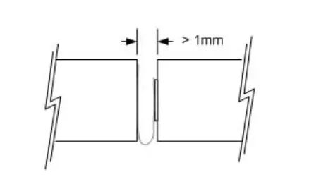
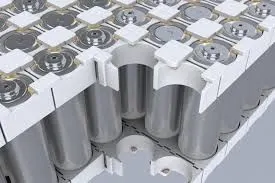
The cell vents, located on the end cap(s) of the cells (on the POSITIVE side of the cell), should not be blocked by any mechanical means. Blocking the cell vent and then sufficiently abusing the cell so as to build up pressure in the cell prevents the cell from properly venting. An ESS designed to install cells end-to-end needs at least 1 mm of space between the cells to allow the vent to open under fault conditions.
CELL INSULATION:
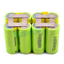
The outside case of the 26650 and 32113 is electrically connected to the positive end(cathode) of the cell. Take care to keep this surface electrically isolated from an electrical bus bar or mechanical support that may be of different voltage potential. Insulation, such as tapes, shrink wraps, or sleeves, must have at least a 150 °C melting point. This helps ensure that the cells do not short circuit to each other at a high.
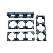
CELL SUPPORT:
Secure the cells in place by supporting their outside cases, not their terminal ends. The vibration-induced between the terminal ends and the rest of the case has been shown to be detrimental to the life of the cell, causing internal and external cell damage. The Theintercell terminations must be light enough not to cause vibration-induced damage to the cell.
CELL PROTECTION:
In addition to being supported, protect cells from exposure to corrosive substances and oxidizing catalysts, such as dust and moisture. The necessary level of protection for cells in a battery pack varies depending on the intended application. For example, a battery pack designed for use in an HEV must have an enclosure that isolates cells from shock and vibration, protects them from dirt and debris, as well as shields them from other environmental dangers, such as salt spray. Unless it is hermetically sealed, even a sealed enclosure is subject to pressure differentials between its insides and the ambient, causing minute amounts of air exchange. Therefore, over time, some moisture may accumulate and condense on inside surfaces. An ESS designed to be sealed from the environment(from dust, moisture, and VOCs) must have a way to benignly drain off whatever condensate does manage to leak into it. In addition, enclosures protecting cells must
work with the thermal management system to achieve optimum durability and safety of the battery pack. For example, a poor choice of materials for the enclosure, combined with insufficient cooling and controls, may cause the battery pack to overheat.
THERMAL MANAGEMENT:
cells operate throughout a wide temperature range; however, they are most effective between 10°C and 50°C. The temperature differential between the coolest cells and the hottest cells should be no more than 10°C. Careful attention to thermal management is necessary to keep the cells operating at peak efficiency and avoid fault conditions. In most cases, this implies a cooling system. There are certain applications - such as HEV vehicles operating in cold climates - where a heater is beneficial to keeping the cells operating in their optimal range.
TECHNICAL DATA:
CELL MONITORING:
To ensure optimal performance, safety, and durability of the pack, the BatteryManagement System must monitor the voltage of each individual series cell in a battery string. Take care to place the voltage monitoring connections in such a place that they are not affected by high currents going through the interconnection elements.
The diagram below depicts an optimal positioning of the voltage monitoring contact points in an idealized setting.
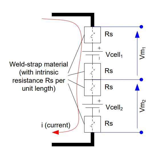
In this case, Vm1 = Vcell1 – 2 x i x Rs and Vm2 = Vcell2 – 2 x i x Rs. The result of Vm1– Vm2 would be exactly what is desired, and that being Vcell1 – Vcell2
If the contact points are placed asymmetrically, such as shown below
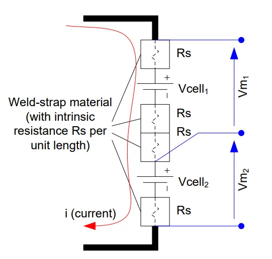
Vm1 = Vcell1 – 3 x i x Rs and Vm2 = Vcell2 – i x Rs. The result of Vm1 – Vm2 would contain an undesirable offset in it: Vcell1 – Vcell2 + I x Rs where Voffset = I x Rs. This offset in the voltage readings would cause the BMS to read that there is more charge in one cell while the current is flowing in one direction, and have less charge in it while the current is flowing in the opposite direction. So while the battery is discharging, the BMS would balance some of the cells, and while it is recharging, the BMS would balance the others. This results in a great deal of wasted heat and energy that contributes to reduced performance and service lifetime of the battery. Ensure that balancing currents do not share the voltage sensing leads. Otherwise, the balancing currents will affect the voltage reading proportionally, increasing the time needed to achieve proper cell balancing, if not making it impossible.
The following circuit depicts a condition in which the measured voltages would be affected by balancing currents going through the sense leads:
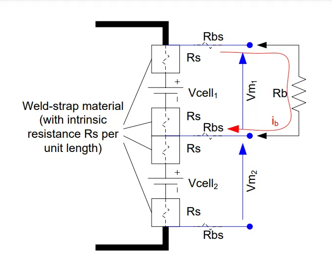
In such a case, if Rb were connected to cell 1, Vm1 would read Vcell1 – ib x 2 x (Rbs +Rs). Having a separate wire for balancing current from the sensing wires eliminates a good portion of the error, as shown in the following diagram:
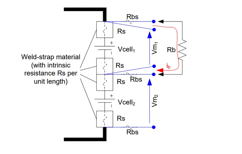
CELL BALANCING:
REASON FOR CELL BALANCING: Each cell in every battery string will have different rates of self-discharge with respect to each other. Cell voltage divergence due to variations in cell construction, environment, and aging requires some means of balancing. Three factors can cause series elements to diverge from each other over time.
CONSTRUCTION VARIATIONS: In the cell manufacturing process and operational conditions. Tolerances in the electrode material loading, active material make-up,and other factors can lead to how fast each cell will lose charge over time.
ENVIRONMENT VARIATIONS: In-cell temperature across the series string can lead to different rates of self-discharge in each of the series elements.
AGING VARIATIONS: cell performance can grow over time as each of the cells ages differently in response to its environment and physical construction.
SHORT CIRCUIT PROTECTION:
Because of the very low impedance of the A123 cells, a short circuit can cause excessive internal and external damage if not limited in either duration or current magnitude.
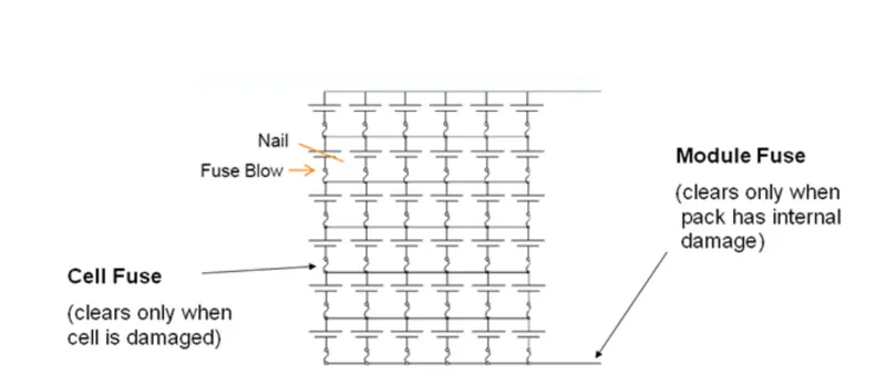
Layered fusing in the pack interrupts excessive current at the cell or module level, helping to prevent the main fuse from blowing. Likewise, a fault at the module level will not cause the cell fuses to blow. This is considered best practice in the circuit protection field.
INDIVIDUAL CELL FUSING:
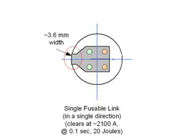
You can achieve the circuit protection strategy described above by having the individual cell fuses operate at a higher fault current than that of the module. Likewise, design the
module fuse to blow at a higher level than the main pack fuse. Refer to Figure 9 for an illustration of an individual cell fusing strategy.
EXAMPLE:
MODULE FUSE RATING:
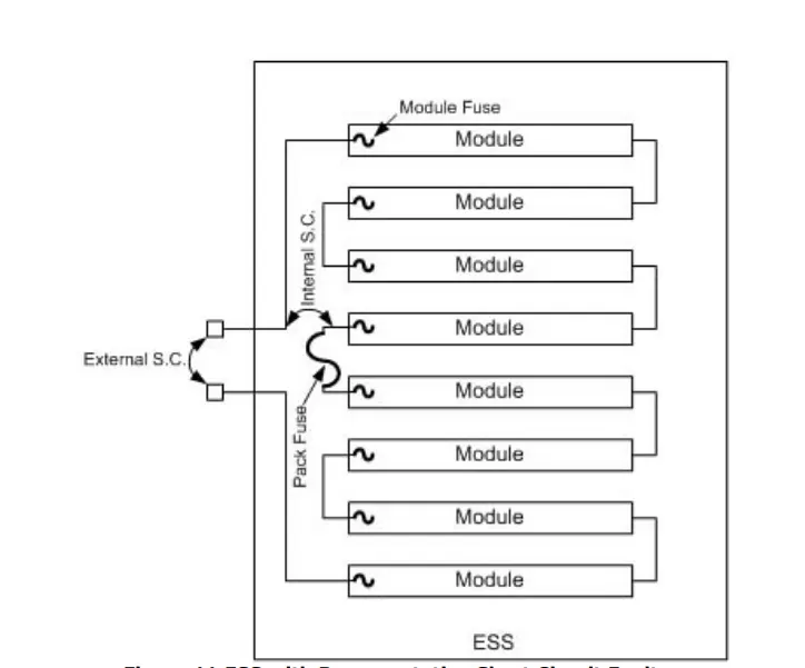
Design the module fuse to blow at a lower current than that of the individual cell fuses. This ensures that the module blows before any of the cell fuses do in response to a fault
on the module terminals. In addition, the module fuse must interrupt any short circuit path that may exist around multiple series modules situated between the main pack fuse and possible short circuit locations.
OVERCHARGE PROTECTION:
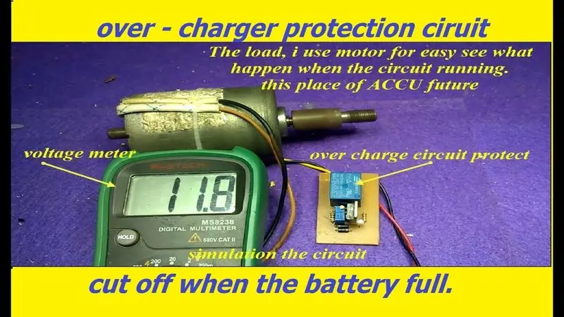
Using individual series cell voltage monitoring, the BMS can employ a means to protect any cell from being overcharged. Some of these means include opening an input
contactor, FET, or another switch in series with the battery terminals, or by communicating a smart external charger to adjust its output appropriately. Because overvoltage is a sure way to ruin the cells, a best practice technique is to make sure there are redundant methods for monitoring and controlling the cell voltage. For example, if a microprocessor is involved in the decision-making process, employ an analog circuit to watchdog the processor or cell voltages. If an analog circuit is the only method to watch the circuit, use two for redundancy.
PERFORMANCE TESTING:
ESS performance testing validates that the ESS performs basic application functionality in the application’s intended environment. These tests include discharge, recharge, cycling, open circuit, thermal, and environmental testing. Applications for each ESS can vary significantly, so the key to these tests is to frame the test conditions around the conditions of the expected application.
PERFORMANCE TEST:
| NAME |
DESCRIPTION |
| CC | Constant Current Discharge – Test Capacity of ESS using various constant current loads |
| PP | Peak Power Discharge – Test Power Capability of ESS using 2/3 OCV. I.e. determine at what power levels, the battery voltage falls to 2/3 of the starting OCV |
| Application-Specific Cycle Tests |
Cycle the ESS using the application’s expected cycle profiles. There are two application cycle testing goals. One is to measure short-term ESS performance and the other is to measure long-term performance over time. The latter takes into account the degradation of the battery over time with respect to the amount of usage the battery experiences. |
| Stand Test | Test Self-Discharge of ESS while off. |
| Thermal | The test temperature rise of cells over ambient temperature during worse-case load conditions. The test Temperature gradient from coolest to hottest cell during worse-case load conditions. |
Abuse testing verifies reactions to harsh and out-of-specification conditions under which the product may be exposed. The results of these tests do not necessarily have to show
that the product survives and functions after such tests. However, it is expected that a result of the abuse test show that the product will cause little or no damage to personnel and objects near them. Abuse testing is not intended to acknowledge or validate the design outside of proper operating conditions, even if the test units perform with a safe or acceptable reaction.
ABUSE TEST:
| NAME | DESCRIPTION |
| Short Circuit | Test the ability of the ESS to limit the output energy in the case of an accidental short circuit on its terminals. This testing also includes short-circuiting individual elements within the ESS, such as modules, groups of modules, cells and cell groups. |
| Overcharge | Test the ability of the ESS to prevent any one of its cells from being overcharged as a result of excessive voltage being applied to the terminals of the ESS |
| Crush | Understand what happens when the ESS is crushed in a calibrated manner. |
| Drop | Observe the effects of the ESS being dropped from a specified height. |
| Shock | Observe the effects of the ESS being subjected to a large shock in three axes |
| Immersion | Test the ability of the ESS to seal out liquid water when completely immersed. |
Minimize handling of cells to avoid damaging them. Reject any cell dropped from a height of more than 1200 mm. If a cell is dropped from a height of less than 1200 mm, carefully inspect the components for damage and then retest the OCV and alternating current. resistance (ACR). Reject any cells where damage exceeds acceptable limits or either OCV
or ACR is not within specified limits. Discard any cells that have been subjected to even a brief external short circuit. Do not damage the cells in any way that would make them unfit for your intended use.
AMBIENT CONDITIONS:
Store and process cells in an environment of 15°C to 35°C and less than 75% relative humidity. Keep the cells undercover and protected from the elements at all times.
RESULTS:
HERE WE CAN PREPARE A DETAILED BATTERY PACK DRAWING ALONG WITH ITS ENCLOSURE.