Project 1 Mechanical design of battery pack
Aim :
- Mechanical Design of the Battery pack
Objective :
- Battery pack capacity: 18 kWh
- Cell: ANR26650M1-B
- Prepare a detailed battery pack drawing along with its enclosure. State your assumptions.
About Cell ANR26650M1-B
ANR26650M1 is A123's high-performance lithium iron phosphate(LiFePO4) battery technology that delivers high power and energy density combined with excellent safety performance and extensive life cycling in a lighter-weight more compact package. These cells have a low capacity loss and impedance growth over time as well as high usable energy over a wide state of charge range. allowing our system to meet end-of-life power and energy requirements with minimal pack oversizing.
Dimension of ANR26650M1-B
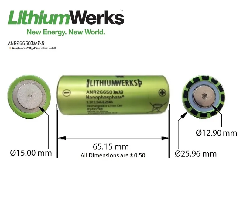
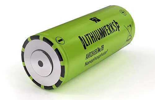
Specifications Of ANR26650M1-B :
| Cell dimensions | 26*65 mm |
| Cell weight | 76g |
| Cell Capacity(nominal/minimum)(0.5C rate) | 2.5/2.4 Ah |
| Voltage(nominal) | 3.3V |
| internal impedance | 6 mOhm |
| power | 2600W/kg |
| Recommended Standard charging method | 2.5A to 3.6V CCCV,60 min |
| Recommended Standard charging method to 80% SOC | 10A to 3.6v CC,12 min |
| maximum continuous discharge | 50A |
| maximum pulse discharge | 120A |
| cycle life at 20A discharge (10 seconds) |
>1000 cycles |
| operating temperature |
-30c to 55c |
| storage temperature |
-40c to 60c |
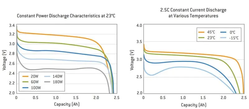
Discharge characteristics of cell
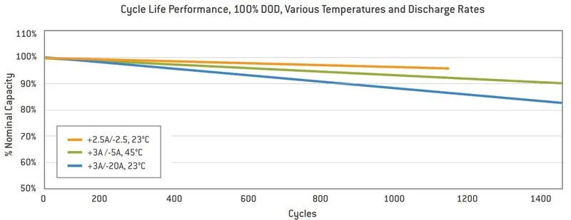
cycle life performance
Application :
- Datacenter UPS
- Telecom backup
- IT backup
- Autonomously guided vehicles (AGVs)
- Industrial robotics and material handling equipment
- medical devices
Government solutions
- military vehicles
- military power grid
- soldier power
- directed energy
Grid solutions
- frequency regulation
- renewable integration
- reserve capacity
- transmission and distribution
Transportation solutions
- commercial vehicles
- off-highway vehicles
- passenger vehicles
Battery Pack :
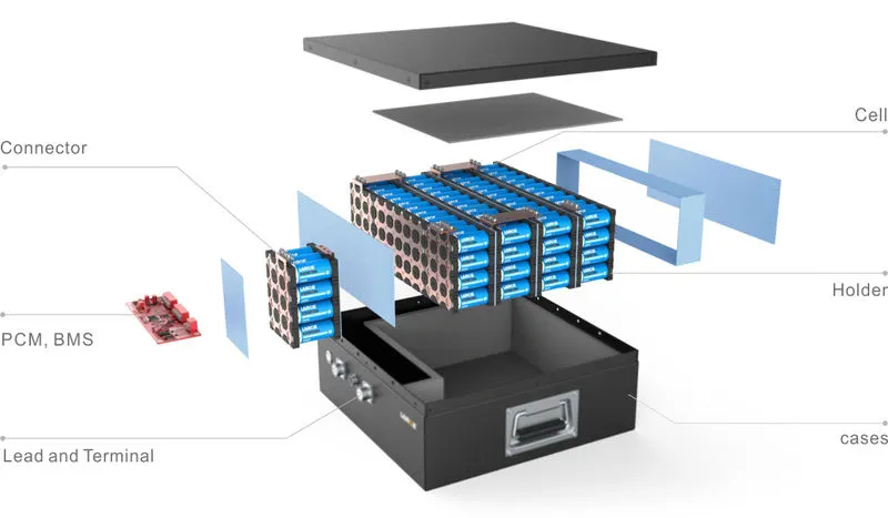
From the objective, we need 18 kWh energy capacity. And such high energy capacity is not delivered by the single-cell So to get high energy capacity we need to connect the number of cells in series or parallel connections to get such high energy capacity and to form a battery pack
Calculating the number of cells:
Pack energy = 18,000 Whr
Assume the battery pack voltage we require (Nexon EV) =320V
Pack Capacity = Pack energy /Pack voltage = `18000/300`= 56.25 A.hr
Number of cells in Series = Pack Voltage /Cell voltage = `300/3.3`=91
Number of cells in Parallel = Pack Capacity /Cell Capacity =`(56.25 Ahr)/(2.5 Ahr)` = 23
Configuration = 91S23P
So,Total number of cells = 91*23 = 2093 cells
Cell Electrical connectors and joining Technologies
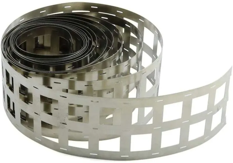
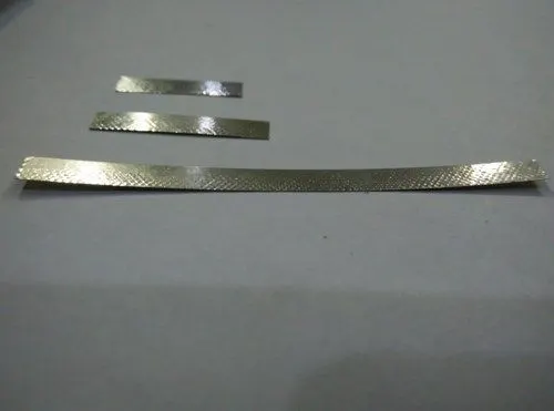
for the internal connection, nickel strips are used. Nickel is an essential component for the cathodes of many secondary battery designs. Nickel strip is generally used in battery building. Its due to its efficiency of usage in spot welding and soldering as well as its high corrosion resistance over time. It has good properties and excellent resistance to many corrosive environments. The pure nickel will never get rust after it is applied to battery packs. Nickel strips are used as battery connectors because they have 20-30% more conductivity than other materials
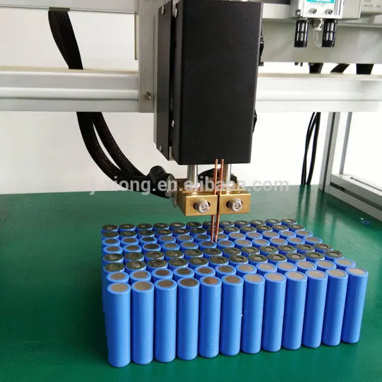
Resistance welding(Spot welding)
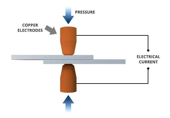
Resistance welding relies on the electrical resistance at the metal interface to cause localized heating and fusion of materials. The pressure exerted by the electrodes, through which the electrical current flows, holds the workpieces to be welded in close contact before, during, and after the welding cycle Resistance welding process is very fast and can be easily automated. It has a wide application in the automotive, electronics, and heavy industries
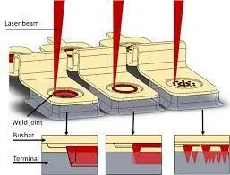
Laser welding
Laser welding is a non-contact process that joins multiple pieces of metal through the laser. The weld is formed as the intense laser beam rapidly heats the material, typically in milliseconds. Laser welding is used to weld battery electrolyte containers, interconnectors, and bus components. As a noncontact welding process, laser welding has several advantages for battery pack manufacturing. Since welding with a low-power pulsed Nd: YAG laser produces the smallest heat-affected zone and a possibility of multiple sheets joining, laser welding is sometimes considered the optimum welding tool for applications involving lithium-ion batteries.
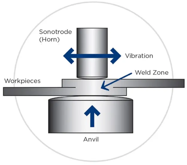
Ultrasonic welding
Ultrasonic metal welding is a process in which a high frequency, usually 20 kHz or above, of ultrasonic energy is used to produce oscillating shears to create solid-state bonds between two sheets clamped under pressure. Ultrasonic welding can be used to join a wide range of types of metal sheets or thin foils. The lateral forces, generated at high frequency, break down contamination and produce an atomic bond between metal interfaces at elevated temperatures. In contrast to traditional fusion welding processes, ultrasonic welding has several inherent advantages derived from its solid-state process characteristics. The main advantage of ultrasonic welding is that it works well for dissimilar materials and multiple sheets, which is crucial for cell joining as well as for battery tab joining [24]. Ultrasonic welding is attractive for battery manufacturing because of its low temperature and relatively good performance for Al, Cu, and other highly conductive materials.
Summary of cell joining method
|
Joining methods |
Advantages |
Disadvantage |
|
Resistance welding |
|
|
|
Laser welding |
|
|
|
Ultrasonic welding |
|
|
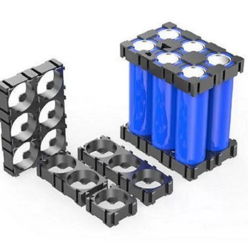
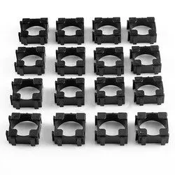
cell holder:
The primary function of a battery holder is to keep cells fixed in place safely and securely while conveying power from the batteries to the device in question. External connections on battery holders are most often made by contacts either with pins, surface mount feet, soldered lugs, or via a set of wire leads.
Housing or Outer Package :
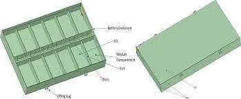
the design of the outer package or housing of the battery depends to great extent on the components it has to accommodate the physical protection. These components are not just cell but also protection devices, electronic circuits, interconnections, and connectors which must all be specified before the final battery case be designed for high energy batteries robust packaging is required for safety reasons
Design Options :
- Aluminum 6061,10 mm base plate
- Stainless steel,5mm base plate
- Stainless steel,4mm base plate
|
Length of Pack = (no cell in series*cell diameter)+(no of cell in series -1)*4mm+10mm = (91*26)+(91-1)*4+10 = 2736 mm Breadth of pack = (no cells in parallel *cell diameter)+(no of cell in parallel-1)*4+10 = (23*26)+(23-1)*4+10 =696 mm height of pack = height of cell +2*1mm bus plate+space for ventilation = 65+2*1+2.85 = 70 mm |
|
Outer dimension of pack(10 mm Al plate) Length = 2736+20 = 2756 mm Breadth = 696+20 = 716 mm height = 70+20 = 90 mm Volume = `V_o - V_i` = (2756*716*90)-(2736*696*70) = 44298720 `mm^3` Density = 0.0027 `g/(mm^3` mass = volume*density = 44298720*0.0027 =1,19,606.544 grams = 119.6065 Kg |
|
Outer dimension of pack(5 mm SS plate) Length = 2736+10 = 2746 mm Breadth = 696+10 = 706 mm height = 70+10 = 80 mm Volume = `V_o - V_i` = (2746*706*80)-(2736*696*70) = 21796160 `mm^3` Density = 0.008 `g/(mm^3` mass = volume*density = 21796160*0.008 =1,74,369.28 grams = 174.369 Kg |
|
Outer dimension of pack(4 mm SS plate) Length = 2736+8 = 2744 mm Breadth = 696+8 = 704 mm height = 70+8 = 78 mm Volume = `V_o - V_i` = (2744*704*78)-(2736*696*70) = 17380608 `mm^3` Density = 0.008 `g/(mm^3` mass = volume*density = 17380608*0.008 =1,39,044.864 grams = 139.044864 Kg |
from the above calculation result for battery pack casing ss plate with 4 mm thickness is most suitable because its weight just slightly more than the aluminium plate but it save a lot of space being 4mm thick as compare to the aluminium plate which is 10 mm thick.
Result :
Battery pack dimensions :
internal = 2736 mm *696 mm*70 mm
external or housing = 2744 mm*704 mm*78 mm
pack material is = stainless steel with 4mm thickness and the insulated sheet between the pack and the copper bus plate
Assembly of the battery pack :
step 1:
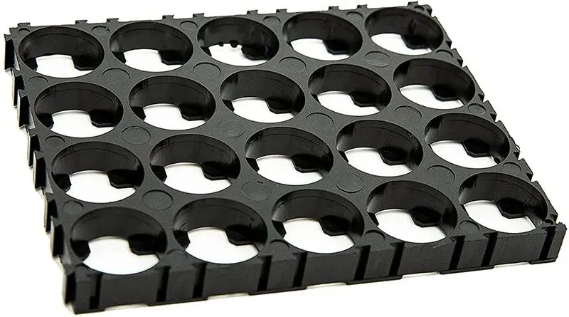
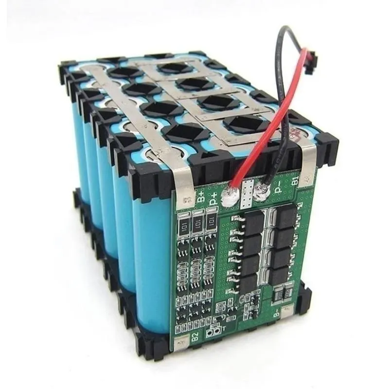
start with snapping the square holder together as per our number of cells. and put the insulating gasket on the positive side of the cell.
Step 2:
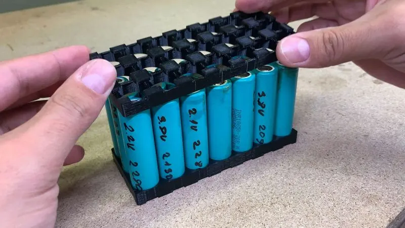
Now place the cells in the cell holder matrix. After loading all cells put the second cells connector block on another side.
Step 3 :
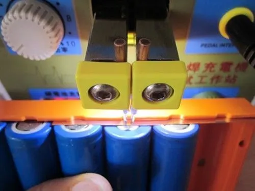
connecting the cells using the nickel strip. We can use the H type of nickel strip or single nickel strip. using the nickel strip series and parallel connections are made.
As above mentioned we have different types of joining methods we can prefer resistance (spot) welding as it takes less cost as per the other welding method and it is a fast process
step 4 :
After connection, stick PVC sink film to cell. Connect the Balancing wire pin to BMS and glue it to the side of the battery pack with BMS.
Step 5:
now put the battery pack in the housing which is made as per the above calculation.
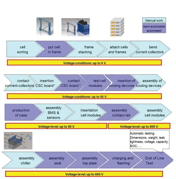
Overall view from start to end Mechanical battery pack:
Conclusion :
- These are the process or things to take in consideration while mechanical design of battery pack