Project 1 Mechanical design of battery pack
Battery pack capacity: 18 kWh
Cell: ANR26650M1-B
Prepare a detailed battery pack drawing along with its enclosure. State your assumptions.
Ans-
Batteries and cells are key inventions that have simplified many of our daily duties and lives. They are practically employed in the majority of today's portable electronic products. Furthermore, we might claim that a world without batteries and cells is unthinkable.A chemical reaction occurs between the anode and the electrolyte when the anode and cathode of a battery are linked to a circuit. This reaction sends electrons across the circuit and back to the cathode, where they undergo another chemical reaction. The battery is unable to produce power when the material in the cathode or anode is consumed or no longer usable in the reaction.
One or more cells make constitute a battery. A single cell battery is commonly referred to as a'single cell battery.' When there are multiple cells, they are connected in series inside, but they normally seem as a single object from the outside (one positive and one negative terminal).When it comes to batteries, a cell consists of one metallic cathode (positive), one metallic anode (negative), and electrolyte in its most basic form. The metals used in the cathode and anode, as well as the liquid or material that makes up the electrolyte, varies because numerous combinations have been discovered throughout the last two centuries, each with its own set of strengths and limitations.
ANR266650M1-B have a lot of power because they use unique battery technology. The cells are fundamentally safe over a wide variety of temperatures and environments thanks to their lithium iron phosphate chemistry (LiFePO4). The Lithium Werks 26650 cells are appropriate for a wide range of power, pulse, and stand-by applications, whether the application requires great cycle life or reliable float reliability.
Thermally stable chemistry, faster charging, constant output, reduced capacity loss over time, and lower total cost of ownership are all advantages of nanophosphate battery technology (TCO).
It lays the groundwork for secure systems while also meeting the most demanding client requirements. In comparison to metal oxide lithium-ion chemistries, multiple layers of protection are used at the chemical, cell, and system level to produce an energy storage solution with greater safety and abuse tolerance.
Applications-
Commercial solutions-
- UPS datacentre
- Telecom backup
- IT backup
- Autonomously guided vehicle
- Industrial robotics
- Medical appliances
Government solutions-
- Military automotive
- Military power grids
- Directed energy
Transportation solutions
- Plug in hybrid,hybrid electric vehicle battery systems
From the data sheet of the ANR26650M1-B we have the specification table-
| Nominal Voltage | 3.3V |
| Cell Capacity | 2.5Ah |
|
Internal Impedance
|
6mΩ |
| Maximum Continuous Discharge | 50A |
| Recommended Standard Charge Method | 2.5A to 3.6V CCCV, 60 min |
| Cycle Life at 20A Discharge, 100% DOD | >1,000 cycles |
| Operating Temperature | -30°C to 55°C |
| Storage Temperature | -40°C to 60°C |
| Cell Dimensions | 26 x 65 mm |
| Cell Weight | 76g |
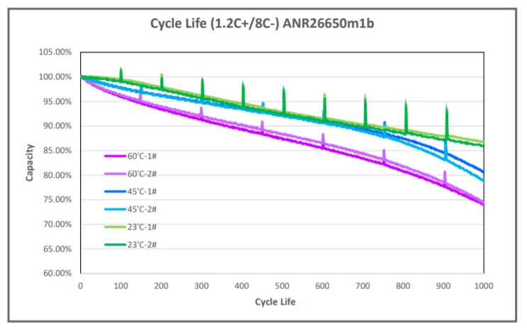
Cylce life characteristics
Discharge voltage profiles
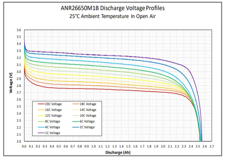
Mechanical design of a battery pack-
Large-scale electrification of the road transport sector faces two major challenges: safety and reliability. Due to factors such as continuous transmission of mechanical vibrations, exposure to strong impact forces, and thermal runaway, current Li-ion battery packs are prone to failure. All of these can be mitigated by using a more robust mechanical design and battery packaging.
We are employing a LiFePO4 chemical cell in this project (Lithium iron phosphate). As a result, the features of LiFePO4 differ significantly from those of other cell chemistries.
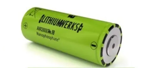
The cathode of lithium iron phosphate is iron phosphate, whereas the anode is graphite. It has a nominal voltage of 3.20V or 3.30V and a specific energy of 90/120 watt-hours per kilogramme. Lithium iron phosphate has a charge rate of 1C and a discharge rate of 1-25C.
Calculations-
we have battery pack capacity =18kWh
Normally the voltage for an electric vehicle ranges from 200 to 800V
Here we are taking the voltage as 450V.
So,
Total energy of the battery pack=18kWh
Number of cells=Total energy of the battery pack/Nominal voltage * Capacity of a cell)
N=18000/(3.3*2.5)
=2182
So we should have 2182 cells for getting a pack capacity of 18kWh ,so the series and parallel combination of the cell should be configured with respect to the capacity.
In parallel combination the capacity will be increasing and the voltage will have the same value,
But in the case of series the voltage will increase according to the no. of cells and capacity will have constant value,
From the cell we have taken the nominal voltage of the cell is 3.3V,and we are taking the battery pack voltage as 450V,
Number of cells in series needed to make 450V =Voltage needed/Nominal voltage of a cell
Ns=450/3.3
Ns=136.36=137
The series configuration should have 137 cells which can generate 400V and the capacity of the pack is 2.5Ah,
So the parellel configuration cell number should be also finded,
No of cells in parellel(Np)=Total no. of cells /No. of cells in series
Np=2182/137
=16
So the parallel configuration have 16 no. of cells,the total configuration of the pack will be 136 series and 16 parallel,
Cell configuration will be 136S16P
Battery capacity should be also calculated,
Capacity=No. of Parallel cells*capacity of a cell
=16*2.5
Capacity=40 Ah
Current supplied is is 40Ah that is in one hour 40A current will be supplied.
Now lets calculate the efficiency of the battery pack,
Assuming Energy consumption=150Wh/km at 60% efficiency
Range of the an ev=Capacity of the battery/Energy consumed per kilometre
Range=18000/150
Range=180 km
So the range of the vehicle will be 120km,and it can be varied according to the driving conditions,
Battery dimensions-
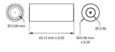
ANR26650M1-B cell has a dimension of 26mm diameter and height of 65mm,According to these dimensions the battery sixe is determined.
Length of casing(L)=number of cells at series*(diameter of cell + cell margin length)+clearance length(edge cell diameter+margin)
L=136*30+60
L=4140mm
Breadth of the casing=Number of cells in parallel*(diameter of cell + cell margin length)+clearance length(edge cell diameter+margin)
B=16*30+60
breadth=540mm
Battery case height(H)=65+35(Cell height+wiring margin,cell holder and metal strip space)
H=100mm
Now the weight of the battery pack should be calculated,
Weight of individual cell=76g
Total no. of cells=2182
Weight of the battery pack=Weight of individual cell*cell number+Weight of accessories
W=2182*76+5=165.8+4.5=170.3kg
We can look into the design aspects of the battery pack
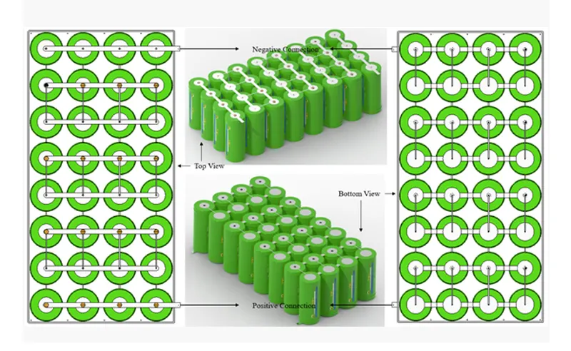
Mechanical interconnects should be designed to prevent unintentional short circuits. For both the maximum time and ambient temperature in which the pack is projected to run, size these mechanical interconnects to carry the predicted maximum rated current.
Cell interconnects-Cell interconnects should be sized for the greatest current carrying capacity expected. Improperly sized tabs may overheat, resulting in even greater resistance. A123 Systems recommends pure nickel tabs or nickel-clad copper tabs for reliable welded connections at the terminals. Other alloys, on the other hand, provide weldability, strength, and low resistance, all of which are desired qualities in a successful interconnection. End caps should not be soldered, and cell interconnects (tabs) should not be joined with excessive heat. Tabs should be resisted or laser-welded to both ends of the cells, according to A123 Systems.
Through a prominent feature in the weld tab, resistance welding produces a continuous current for a defined period of time. For a consistent high-quality weld every time, these parameters can be established and regulated.
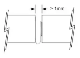
Space between each cell-Any mechanical means should not be used to block the cell vents, which are placed on the end cap(s) of the cells (on the POSITIVE side of the cell). The cell vent is blocked, and then the cell is sufficiently abused to build up pressure in the cell, preventing the cell from venting correctly. To allow the vent to open during fault conditions, an ESS intended to install cells end-to-end requires at least 1 mm of gap between the cells.
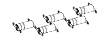
Series string connection
By connecting the positive terminal of one cell to the negative terminal of the next cell, cells in series can obtain higher operating voltages. Using their current collection tabs, connect strings of series cells in the same way as shown in Figure.
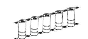
Parallel string connection-
By connecting the like-polarity terminals of nearby cells, cells in parallel strings can reach larger operational capabilities. Connect strings of parallel cells using their current collection tabs in the same way that Figure shows.
The most popular cell type in use today is cylindrical cells. This architecture enables more automated procedures and approaches, which improve consistency while lowering costs.
Cylindrical cells can be made significantly faster than prismatic cells, allowing for more KWh per cell to be produced each day, resulting in lower $ per KWh. In a cylindrical cell, the electrodes are tightly coiled and contained in a metal casing to prevent electrode material from breaking up due to mechanical vibrations, thermal cycling from charging and discharging, and mechanical expansion of the current conductors inside due to thermal cycling. To boost voltage and capacity, several cells are connected in series and parallel.
Using of Nickel strips-
Nickel strip is commonly used in the manufacture of batteries. It's because of its efficiency in spot welding and soldering, as well as its long-term corrosion resistance. It has good characteristics and is resistant to corrosive environments in a variety of ways. After being sprayed to battery packs, pure nickel will never corrode. The current transfer between the batteries will not be affected.
The material you seek is pure nickel strips, but many vendors substitute nickel-plated steel strips, which are inferior and have higher resistance, making them unsuitable for most battery projects.
Reference-
- https://lithiumwerksbatteries.com/
- https://www.batteryspace.com/prod-specs/6610.pdf