Project 1 - Loss calculation for a DC/DC converter-MATLAB
EV Refresher Batch5:
Aim: To design a boost converter and calculate its loss of different components including the power switching device and derive the efficiency of the boost converter.
Let us say
`V_("in")=100V` and we need the output voltage of 200V and the output power needed is
`P_(out)=2kW`
then the output current would be `I_(out)=20A`
then the load resistor is designed to be
`R_(Load)=V_(out)/I_(out)=cancel200/cancel20=10Omega`
let us see the block diagram of the boost converter that we want to design
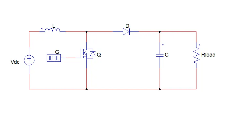
let us design the inductor for the above boost converter
for calculating the inductor we need to know what is the ripple current
a good estimation for the inductor ripple current is 20% to 40% of the output current
let us assume 20%
then
`DeltaI_L=0.2xxI_(out)xxV_(out)/V_("in")`
`=>DeltaI_L=0.2xx20xx200/100`
`:.DeltaI_L=8A`
Now let us calculate the inductance of the boost converter
`L=(V_("in")xx(V_(out)-V_("in")))/(DeltaI_Lxxf_sxxV_(out)`
Now again we need to know the minimum switching frequency, higher switching frequency lowers the ripple current but a higher frequency also gives the noise so let us assume the switching frequency `f_s=10000`
now the inductance would be
`L=(cancel100xxcancel((200-100)))/(8xxcancel10000xx200)=1/1600=0.000625=0.625mH`
now we have to calculate the value of capacitance
for calculating the value of capacitance we need to know the duty cycle of the boost converter
Duty cycle `D=1-(V_("in")xxeta)/V_(out)`
the efficiency of the converter is assumed to be 80%
`D=1-(cancel100xx0.8)/cancel200=1-0.4=0.6`
now the capacitance value is given by
`C = (I_(out)xxD)/(f_sxxDeltaV_(out))`
we have to know the value of `DeltaV_(out)=(I_(out))/(1-D)+(DeltaI_L)/2`
`:.DeltaV_(out)=(20/(1-0.6)+8/2)=20/0.4+4=54`
Now the output capacitance is given by
`C_(out)=(20xx0.6)/(10000xx54)=2.23e-5=2.23muF`
by the calculated values let us model the boost converter in MATLAB/Simulink
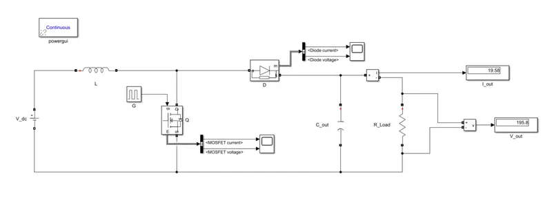
we can observe the output voltage is 195.8which is approximately equal to 200V that what we have desired and the output current is 19.58 which is approximately equal to 20A so we achieved the desired output let us see the voltage and currents of MOSFET and Diode
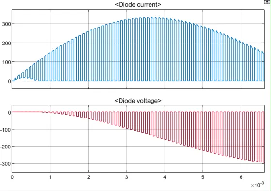
we can observe that the during switch off the diode exhibits the reverse voltage characteristics the peak current in the diode is 300A
let us see the MOSFET results
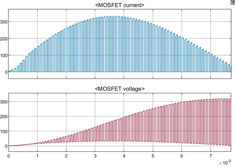
we can observe that the peak voltage and current values are above 300
so we have to select the MOSFET that can withstand a voltage of 300
the spike at the starting is eliminating snubber and a DC link Capacitance
let us go to INFINEON to select the MOSFET for this application
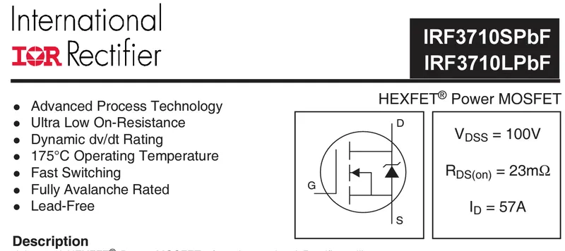
the above MOSFET is connected in series to reach the operating region
now let us calculate the losses
Conduction Losses:
when the integrated high-side MOSFET turns on, the load current flows through it. The drain to source channel resistance (`R_(DS(on))`)causes power dissipation
The Rdson for the selected MOSFET is 0.00023ohms we have to connect the MOSFETs in series in order to reach the peak voltage sp the Rdson is equal to 0.00023
then the conduction loss is given by
`P_c=I_m^2xxR_(Ds(on))xxD`
`P_c=300xx0.00069xx0.6=0.1242`
Diode Losses:
The forward voltage of the diode is given by 0.8
then the diode loss is given by
`P_D=V_fxxI_(out)xx(1-D)`
`=>P_D=0.8xx300xx(1-0.6)=96`
Induction losses
`P_L=I_(out)^2xxR_L+R_L/12((DxxV_("in"))/(FxxL))`
`=>P_L=19.58^2xx0.0000010+0.00000010/12xx((0.6xx100)/(50xx0.625xx10^-3))`
`:.P_L=0.7362`
Capacitance Losses:
`P_C=r_cxxD(1-D)I_(out)^2+r_c/12(1-D)xx((DxxV_("in"))/(CxxF))`
`=>P_C=0.000002xx0.6(1-0.6)xx20^2+0.000002/12(1-0.6)xx((0.6xx100)/(2.23xx10^-3xx50))`
`:.P_C=0.0002278`
now let us calculate the Total power losses in the above converter
`P_T=P_c+P_D+P_L+P_C`
`=>P_T=0.1242+96+0.7362+0.0002278`
`Power Losses =96.8606278W`
Now the efficiency of the boost converter is given by
`eta=1-P_(out)/P_("in")`
the input power is 100 x 20 which is 2000W
the output power is given by 195.8 x 19.58 which is 3833.764
now considering the power losses the efficiency is given by
`eta=1-3833.764/2000`
`:.eta=0.916882`
the efficiency of the above boost converter is 0.91682 which is equal to 91.6882
Conclusion:
The Boost Converter is designed and modeled in Simulink and the switching device is selected from the retailer as well as the power losses of different components and also the switching device is determined as well as the efficiency of the designed converter is calculated.