AIM:Interfacing a 16*2 LCD with Arduino using I2C protocol
SOFTWARE: TINKERCAD
THEORY: Several functions of Arduino's Wire Library are used to accomplish this. Arduino 1, the Master, is programmed to request, and then read, 6 bytes of data sent from the uniquely addressed Slave Arduino. Once that message is received, it can then be viewed in the Arduino Software (IDE) serial monitor window.
- A serial clock pin (SCL) that the Arduino Master board pulses at a regular interval
- A serial data pin (SDA) over which data is sent between the two devices.
a single bit of information - that will form in sequence the address of a specific device and a a command or data - is transferred from the board to the I2C device over the SDA line.
When this information is sent - bit after bit -, the called upon device executes the request and transmits it's data back - if required - to the board over the same line using the clock signal still generated by the Master on SCL as timing.
it is possible for your Arduino board to communicate (in turn) with many devices, or other boards, while using just two pins of your microcontroller.
program for master
|
// include the library code:
#include <LiquidCrystal.h>
#include <IRremote.h>
int swtch = 10;
IRrecv irrecv(swtch);
decode_results results;
// initialize the library with the numbers of the interface pins
LiquidCrystal lcd(12, 11, 5, 4, 3, 2);
int state;
void setup() {
Serial.begin(9600);
pinMode(swtch,INPUT);
lcd.begin(16, 2);
irrecv.enableIRIn(); // Start the receiver
}
void loop() {
lcd.setCursor(0, 0);
if (irrecv.decode(&results)) {
//Serial.println(results.value, HEX);
// Presing back on the remote sets manual mode
if (results.value == 16589023){
lcd.clear();
lcd.print("Mode: Manual");
Serial.println('1');
}
// Pressing next sets auto mode
if (results.value == 16605343){
lcd.clear();
lcd.print("Mode: Auto");
Serial.println('0');
}
irrecv.resume(); // Receive thxt value
}
delay(100);
}
|
program for the slave:
|
#include <IRremote.h>
int EN = 5;
int ONE = 6;
int TWO = 8;
int on = 255;
int RECV_PIN = 11;
char data;
int light = 0;
float sens = A0;
int button =2;
IRrecv irrecv(RECV_PIN);
decode_results results;
void setup()
{
pinMode(ONE,OUTPUT);
pinMode(TWO,OUTPUT);
pinMode(button, INPUT_PULLUP);
attachInterrupt(digitalPinToInterrupt(button),click,FALLING);
//Enable serial usage and IR signal in
Serial.begin(9600);
//Serial.println("Enabling IRin");
irrecv.enableIRIn();
//Serial.println("Enabled IRin");
}
void loop() {
if(Serial.available() >0){
data = Serial.read();
Serial.println(data);
}
while (data=='0'){
if (irrecv.decode(&results)) {
/*
irrecv.decode(&results) returns true if anything is recieved,
and stores info in varible results
*/
unsigned int value = results.value;
//Get the value of results as an unsigned int, so we can use switch case
Serial.println(value);
switch (value) {
case 8415:
data = 1;
break;
}
irrecv.resume(); // Receive the next value
}
light = analogRead(sens);
//Serial.println(light);
delay(100);
if (light>14){
//actual run times commented out for simulation purposes
analogWrite(EN,on);
digitalWrite(ONE, LOW);
digitalWrite(TWO, HIGH);
delay(1000);
//delay(60000);
analogWrite(EN,on);
digitalWrite(ONE, LOW);
digitalWrite(TWO, LOW);
delay(2000);
//delay(7200000)
analogWrite(EN,on);
digitalWrite(ONE, HIGH);
digitalWrite(TWO, LOW);
delay(1000);
//delay(60000);
analogWrite(EN,on);
digitalWrite(ONE, LOW);
digitalWrite(TWO, LOW);
}
}
while (data=='1'){
if (irrecv.decode(&results)) {
unsigned int value = results.value;
//Serial.println(value);
switch (value) {
// Button 1
case 2295:
Serial.println("Test for Remote: Functional");
break;
// Button Down
case 4335:
analogWrite(EN,on);
digitalWrite(ONE, LOW);
digitalWrite(TWO, HIGH);
break;
// Button Up
case 20655:
analogWrite(EN,on);
digitalWrite(ONE, HIGH);
digitalWrite(TWO, LOW);
break;
// Play/Pause Button
case 41055:
analogWrite(EN,on);
digitalWrite(ONE, LOW);
digitalWrite(TWO, LOW);
break;
case 24735:
data = 0;
break;
} irrecv.resume(); // Receive the next value
}
}
delay(100);
}
// Emergency Stop Button
void click(){
analogWrite(EN,on);
digitalWrite(ONE, LOW);
digitalWrite(TWO, LOW);
}
|
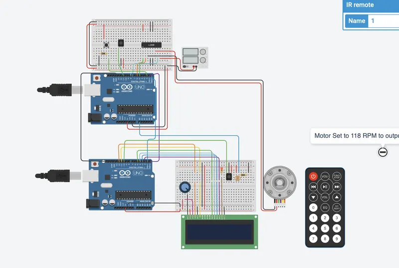
Working:So the motor set to 118v to output 100v for 12v
play/pass acutually stop
the first analog pin
when star simulation: lets go to manual mode we should be able sun turn on the motor kicks on for 1sec after 0.6 turn off two sec reson beacuase go down in time we are going neither 100rpm
https://www.tinkercad.com/things/anLuTVt1QCv-copy-of-awning-lowering-design/editel?tenant=circuits
Output: Using master and slave with UNO is connected to motor and slave is connected to lcd
for Output we can control with remote or emerengy stop button on master uno card controlling the motor the controlling result will display on slave lcd