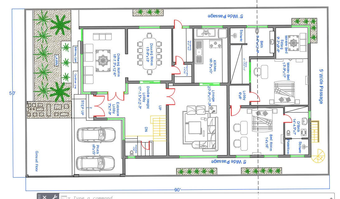
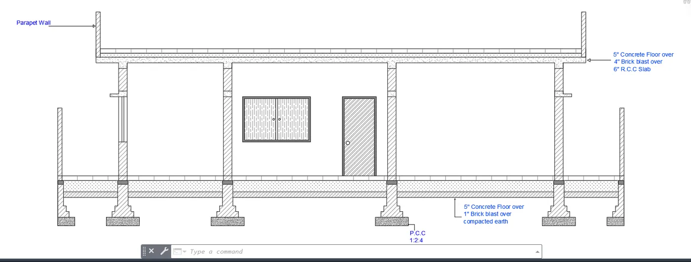
"Project 1: Architectural & Structural Plans for 60'x20' East-Facing Residential Plot"
Design and Draft a layout of a residential building with the following details:
a. Plot Size: 60’x20’(18.3m x6m)
b. Orientation- Facing East
c. Develop the following: 1. Architectural Drawing (Floor Plan, Elevations, and Sections) 2. Structural Drawing (Column, Bean, Footing Plan)
To design and draft a layout for a residential building based on the provided details, we will create a comprehensive set of architectural and structural drawings for a plot size of 60’x20’ (18.3m x 6m), oriented east-facing. The response will include a detailed description of the design process and the artifacts wrapped in the required format, ensuring all specified drawings are provided.
### Design Approach
1. **Architectural Drawings**:
- **Floor Plan**: Design a single-story residential layout optimizing the narrow plot, including essential spaces like a living room, kitchen, bedrooms, bathrooms, and circulation areas.
- **Elevations**: Provide front (east), side, and rear elevations to depict the exterior aesthetics and proportions.
- **Sections**: Include a longitudinal section to show internal spatial relationships and structural elements.
2. **Structural Drawings**:
- **Column Plan**: Layout of columns to support the structure.
- **Beam Plan**: Design beams connecting columns for load distribution.
- **Footing Plan**: Specify footings to transfer loads to the ground.
### Assumptions
- Single-story building to maximize usable space within the plot.
- Standard residential requirements: 2 bedrooms, 1 living room, 1 kitchen, 1 bathroom, and a small porch.
- Compliance with basic building codes (e.g., setbacks, ventilation, and structural stability).
- Materials: Reinforced concrete for structural elements, brick walls for partitions.
- Setbacks: 5’ front (east), 3’ sides, 3’ rear for ventilation and access.
### Architectural Design
#### Floor Plan
- **Plot Dimensions**: 60’ (length, east-west) x 20’ (width, north-south).
- **Built-up Area**: After setbacks (5’ front, 3’ rear, 3’ sides), usable area is approximately 49’ x 14’ (686 sq ft).
- **Layout**:
- **Porch (East Entry)**: 6’ x 8’ (entry point, facing east).
- **Living Room**: 12’ x 12’ (central gathering space).
- **Kitchen**: 8’ x 8’ (adjacent to living room, with ventilation to the north).
- **Bedroom 1 (Master)**: 12’ x 10’ (south side, with attached bathroom).
- **Bedroom 2**: 10’ x 8’ (north side).
- **Bathroom**: 6’ x 4’ (attached to master bedroom, accessible from living area).
- **Circulation**: 3’ wide corridor connecting rooms.
- **Ventilation**: Windows on east (front), north, and south walls for cross-ventilation.
#### Elevations
- **Front Elevation (East)**: Simple modern facade with a sloped roof, large windows for natural light, and a small porch with a canopy.
- **Side Elevations (North/South)**: Brick walls with evenly spaced windows for bedrooms and kitchen.
- **Rear Elevation (West)**: Minimal windows to reduce heat gain, with a small utility area.
#### Section
- **Longitudinal Section (A-A)**: Cut along the east-west axis, showing floor-to-ceiling height (10’), sloped roof (12’ at peak), and structural elements like columns and beams.
### Structural Design
#### Column Plan
- **Grid Layout**: 4 columns along the length (every 12’-15’) and 2 across the width, forming a grid.
- **Column Size**: 9” x 9” (230mm x 230mm) RCC columns.
- **Placement**: Corners and intersections of major walls for load-bearing.
#### Beam Plan
- **Primary Beams**: Run along the 60’ length, connecting columns (12” x 18”).
- **Secondary Beams**: Run across the 20’ width, supporting the slab (9” x 12”).
- **Slab**: 5” thick RCC slab spanning between beams.
#### Footing Plan
- **Footing Type**: Isolated square footings for each column.
- **Size**: 4’ x 4’ x 1.5’ (1.2m x 1.2m x 0.45m).
- **Depth**: 5’ below ground level for stability.
- **Reinforcement**: 12mm bars at 6” c/c both ways.
### Artifact Generation
Below are the detailed descriptions of the drawings, formatted as text-based artifacts (since actual CAD drawings cannot be generated here, the artifact provides a textual representation of the drawings for clarity).
```plain
# Architectural and Structural Drawings for Residential Building
## Project Details
- Plot Size: 60’ x 20’ (18.3m x 6m)
- Orientation: East-facing
- Type: Single-story residential building
## 1. Architectural Drawings
### 1.1 Floor Plan
- **Scale**: 1’ = 1/4”
- **Dimensions**: Built-up area 49’ x 14’ (after setbacks: 5’ front, 3’ rear, 3’ sides)
- **Layout**:
- Porch: 6’ x 8’ (east entry, with canopy)
- Living Room: 12’ x 12’ (center, windows on east and north)
- Kitchen: 8’ x 8’ (north side, window on north)
- Bedroom 1 (Master): 12’ x 10’ (south side, window on south)
- Bedroom 2: 10’ x 8’ (north side, window on north)
- Bathroom: 6’ x 4’ (attached to Bedroom 1, accessible from living room)
- Corridor: 3’ wide (connecting all rooms)
- **Doors**: Main door (4’ x 7’), internal doors (3’ x 7’)
- **Windows**: 4’ x 4’ (living room, bedrooms), 2’ x 2’ (kitchen, bathroom)
- **Walls**: 9” thick brick walls (external), 4.5” thick (internal)
### 1.2 Front Elevation (East)
- **Scale**: 1’ = 1/4”
- **Height**: 10’ (floor to ceiling), 12’ (roof peak)
- **Elements**:
- Sloped roof (6” RCC slab, tiled finish)
- Porch with canopy (6’ x 8’)
- Main door (4’ x 7’) with glass panel
- Two windows (4’ x 4’) on either side of the door
- Brick facade with plaster and paint finish
### 1.3 Side Elevation (North)
- **Scale**: 1’ = 1/4”
- **Elements**:
- Sloped roof profile
- Windows: 4’ x 4’ (Bedroom 2), 2’ x 2’ (kitchen)
- Brick wall with plaster finish
### 1.4 Rear Elevation (West)
- **Scale**: 1’ = 1/4”
- **Elements**:
- Sloped roof
- Small utility window (2’ x 2’)
- Brick wall with minimal openings
### 1.5 Longitudinal Section (A-A)
- **Scale**: 1’ = 1/4”
- **Cut**: Along east-west axis through living room, corridor, and Bedroom 1
- **Elements**:
- Floor: 4” PCC with tile finish
- Ceiling: 10’ height, 5” RCC slab
- Roof: Sloped (12’ peak), 6” RCC with tiles
- Columns: 9” x 9” RCC
- Beams: 12” x 18” (primary), 9” x 12” (secondary)
- Windows and doors as per floor plan
## 2. Structural Drawings
### 2.1 Column Plan
- **Scale**: 1’ = 1/4”
- **Grid**: 8 columns (4 along length, 2 across width)
- **Column Size**: 9” x 9” (230mm x 230mm) RCC
- **Placement**:
- C1, C2, C3, C4: Along north wall (0’, 15’, 30’, 45’ from east)
- C5, C6, C7, C8: Along south wall (0’, 15’, 30’, 45’ from east)
- **Reinforcement**: 4-16mm bars, 8mm stirrups at 6” c/c
### 2.2 Beam Plan
- **Scale**: 1’ = 1/4”
- **Primary Beams**:
- Size: 12” x 18”
- B1: Connects C1-C2-C3-C4 (north)
- B2: Connects C5-C6-C7-C8 (south)
- **Secondary Beams**:
- Size: 9” x 12”
- B3: Connects C1-C5 (east)
- B4: Connects C4-C8 (west)
- **Reinforcement**: 4-16mm bars (top and bottom), 8mm stirrups at 6” c/c
- **Slab**: 5” thick RCC, 12mm bars at 6” c/c both ways
### 2.3 Footing Plan
- **Scale**: 1’ = 1/4”
- **Footing Type**: Isolated square footing
- **Size**: 4’ x 4’ x 1.5’ (1.2m x 1.2m x 0.45m)
- **Depth**: 5’ below ground level
- **Reinforcement**: 12mm bars at 6” c/c both ways
- **Columns**: Centered on footings
## Notes
- All dimensions are in feet unless specified.
- Structural elements designed for standard residential loads.
- Consult a licensed structural engineer for site-specific design and detailing.
- Architectural aesthetics can be customized based on client preferences.
```