Project 1 _Creating an Architectural plan for the provided plot size and develop relevant basic structural drawings
AIM:-
To create an own Architectural drawing consisting of Floor plan, Elevations and Sections for the plot size 42'x32' and also create the structural drawings for Column, Footing and Beam.
INTRODUCTION:-
The Architectural and Structural drawings are sketched up in AutoCAD using various tools / commands. The given details to draw the same in AutoCAD they are shown below:
Plot Size - 49' x 40'
Orientation - East Facing.
COMMANDS USED:-
- Layers
- Line
- Polyline
- XLine
- Dtext
- MultiLeader
- Dimlinear
- Dimcontinue
- Hatch
- Copy
- Fillet
- Trim
- Erase
- Offset
PROCEDURE:-
- Open AutoCAD software
- Start from scratch
- Set the units to engineering and select ok
- Set limits as lower left corner (0,0) and upper right corner (500',500')
- Go to layer properties < create>
- Architectural drawings:-
- Plan
- Elevation
- Section
- Structural drawings:
- Column Layout
- Footing Layout
- Beam Layout
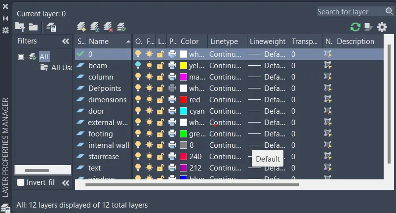
I. ARCHITECTURAL DRAWINGS:-
1. PLAN:-
- Using the line Command, i drew the plot boundary of 49'x40'.
- The building's main entrance is facing the East direction.
- Using the commands line, offset, fillet and trim.
- Starting from the East, the car parking is planned at 15'9''x11 and stairs for about 12'X7'
- The building area is drawn leaving 3' offset distance in the North, West and South directions.
- After providing the offset distance, the floor dimensions comes about 42'x32' including walls,
- Outer walls at 9" thickness and inner walls at 6" thickness is provided.
- I have changed the linetype into CONTINUE for the plot boundary and adjusted the scale for better visibility.
- Now, using the commands Line, polyline, offset, fillet and trim, I have created my own plan for the project.
- The room dimensions are also assumed as per requirement.
- Here, using the line and trim command, i have provided the door spaces as required.
- The Door dimensions are shown below in tabular form.
| DOORS | SIZES |
| D1 | 3'9''x6'8'' |
| D2 |
3'3''x6'8'' |
| D3 | 3'X6'8'' |
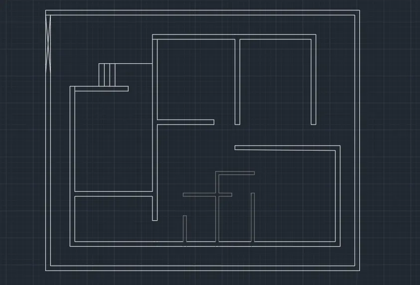
Using the mentioned dimension doors are trimmed and placed and here is the figure attached below.
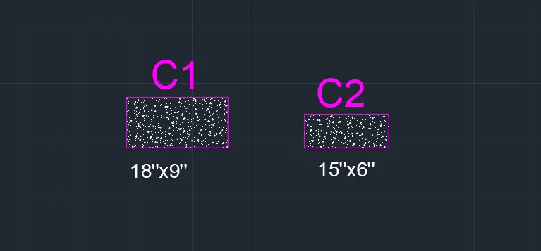
- Using line command, I have Created columns of sizes 18"x9" and 15"x6". Using the Hatch command, I have filled columns with AR-CONC and adjusted the scale for better visibility and copy pasted it wherever required in the floor plan.
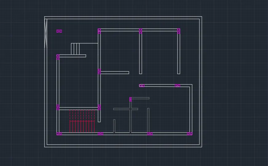
- Stairs are provided using line and offset command, with Tread - 10'' and Rise - 6".
- The Window dimensions are shown below in tabular form.
| WINDOWS/VENTILATOR | SIZES |
| W | 3'4''x2'6'' |
| W1 | 5'6''x9'7'' |
| V | 1'6''X1'6'' |
- Windows are draw as per the dimensioned mentioned above and those are plotted and placed in the plan as per requirement.
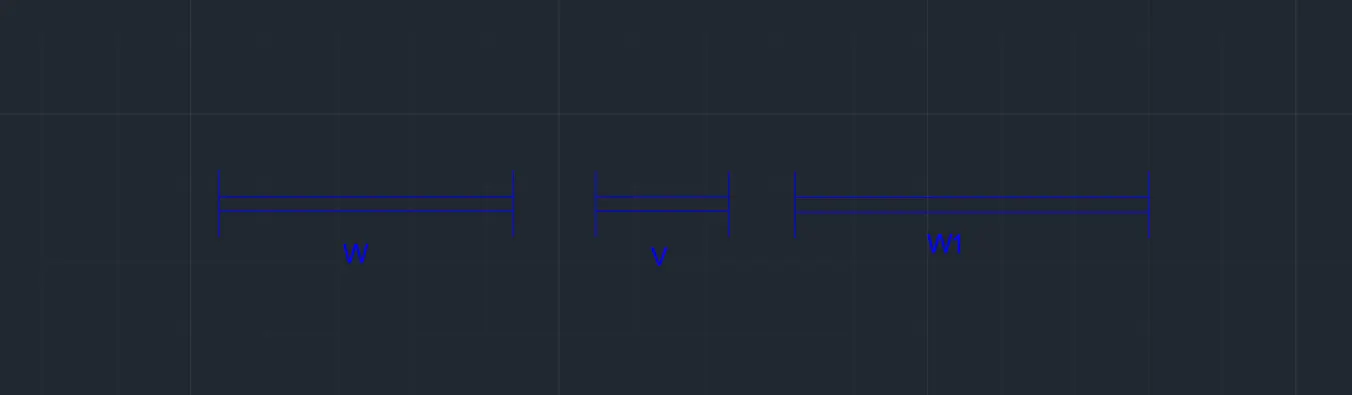
- After placing the windows draw the sunshades.
- Using the DText command, I have mentioned the names for each rooms, spaces, doors, windows and the dimensions for all the rooms.
- Using the commands line, offset, fillet, trim and DText, the compound entrance is created with 9" thickness wall also the car parking and lawn area is surrounded by 9" thickness compound wall.
- Using the DIM-LIN command, I have mentioned the dimensions in the additional spaces and change the layer to dimensions its colors for better view.
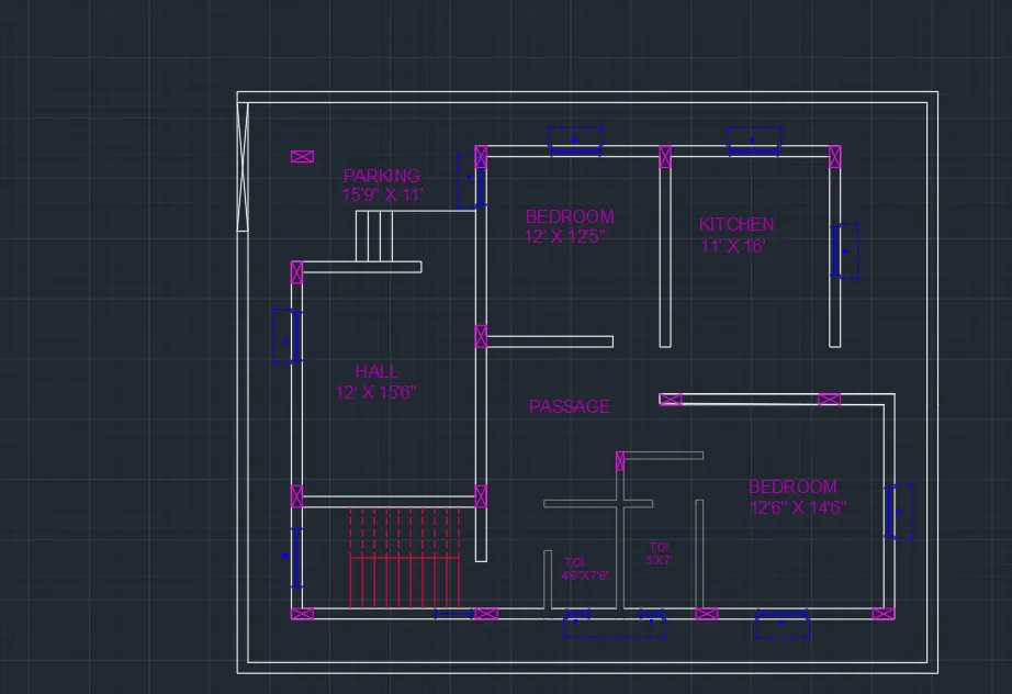
- Using the linetype LONG-DASH SHORT-DASH, I have cut the plan into 1 section, SECTION - AA.
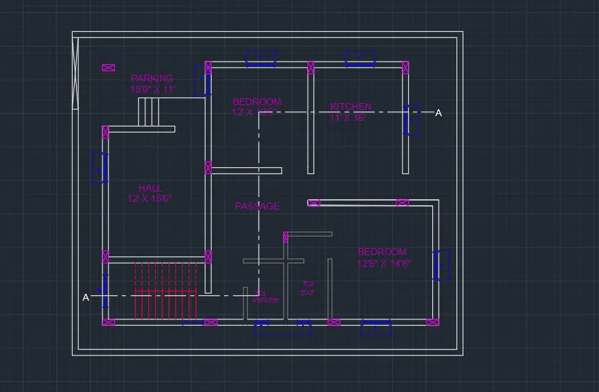
2. SECTION-AA:
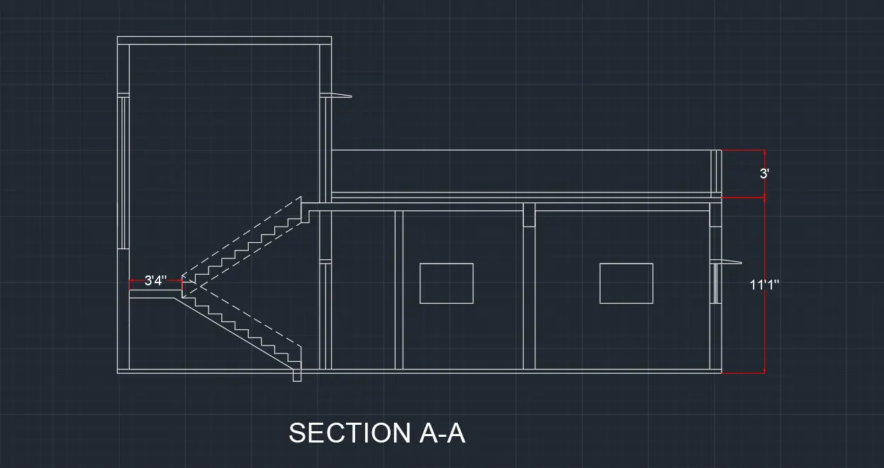
- Using the commands Line, polyline, offset, fillet and trim, I have created the sectional view for the Section -AA.
- Provided windows as per the plan, kitchen space as per plan and stairs as per plan.
- Provided lintel beam over the windows, doors.
- Provided Parapet wall and over head as well
- Using the commands DIM-LIN, I have provided dimensions wherever required.
- And Using DText command, the name is given in the bottom and staircase dimensions are mentioned
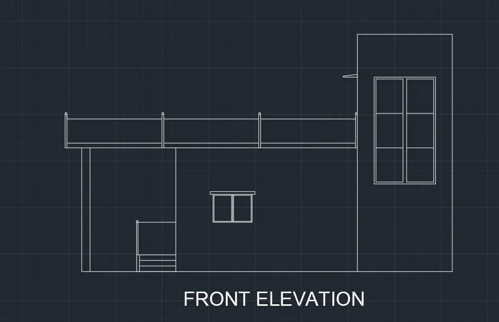
3. ELEVATION:-
- Using the commands Line, polyline, offset, fillet, trim and hatch, I have created the sectional view for the Elevation.
- Provided windows as per the plan, chajja as per plan and door as per plan.
- Provided lintel beam over the windows, doors.
- Provided Parapet wall
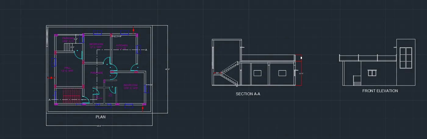
- The following image shows the Ground Floor , Front Elevation and section A together.
 II. STRUCTURAL DRAWINGS:-
1. Column Layout:-
- Turn off all the layers except the column layer and boundary layer in the layer properties.
- Select the Copy tool by typing CO or COPY in the command box.
- Select all the columns from the building plan and copy them to a different location as shown in the figure below.
- Select the Construction line tool by typing XL or XLine in the command box.
- Select the line type as ISO 02W100 and give scale as per requirement.
- Draw lines through the midpoint of the columns in the horizontal and vertical directions as shown in the figure below.
- Select the Trim tool by typing TR or Trim in the command box.
- Trim the unnecessary lines and press Esc to cancel the trim command.
- Select the Dimension tool by typing DIM in the command box.
- Select the first point and the second point of the object to measure. Repeat for all the objects to be measured.
- Enter DS in the command box to open the dimension style manager dialog.
- Modify the dimensions as per the requirement.
- Change the color of the dimension and extension line as per the requirement.
- Give dimensions and text as per the drawing and requirement using the Mtext command and Dimension Command
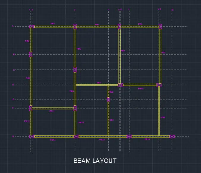
2. Beam Layout:-
- Turn off all the layers except the column layer and boundary layer in the layer properties.
- Select the Copy tool by typing CO or COPY in the command box.
- Select all the columns from the building plan and copy them to a different location as shown in the figure below.
- Select the Construction line tool by typing XL or XLine in the command box.
- Select the line type as ISO 02W100 and give scale as per requirement.
- Draw lines through the midpoint of the columns in horizontal and vertical directions as shown in the figure below.
- Select the Trim tool by typing TR or Trim in the command box.
- Trim the unnecessary lines and press Esc to cancel the trim command.
- Select the Offset tool by typing O or Offset in the command box.
- Select the Trim tool by typing TR or Trim in the command box.
- Trim the unnecessary lines and press Esc to cancel the command
- Assign the beamlines to the beam Layer.
- The naming of PB stand for Primary Beam.
- The naming of SB stands for Secondary Beam.
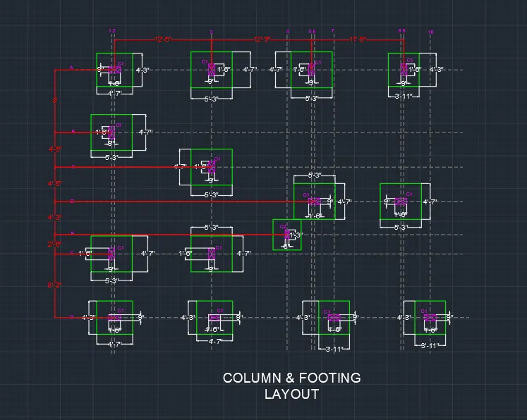
2. Footing Layout:-
- Turn off all the layers except the column layer and boundary layer in the layer properties.
- Select the Copy tool by typing CO or COPY in the command box.
- Select all the columns from the building plan and copy them to a different location as shown in the figure below.
- Also using the DIM-LIN command, the column positions in the footing is mentioned.
- Using ATTRIBUTE command , the Grid names and title is given.
- For better visibility, I have provided colors for grid lines and dimensions between grid lines.
- Select the Trim tool by typing TR or Trim in the command box.
- Trim the unnecessary lines and press Esc to cancel the command
- Select the Dimension tool by typing DIM in the command box.
- Select the first point and the second point of the object to be measured. Repeat for all the objects to be measured.
- Enter DS in the command box to open the dimension style manager dialog.
- Modify the dimensions as per the requirement.
- Change the color of the dimension and extension line as per the requirement.
- Click ok, then click set current and close the dimension style manager dialog box.
- Give dimensions and text as per the drawing and requirement using the Mtext command and Dimension Command.
RESULT:-
- Both Architectural and Structural drawings are shown below again