Project 1 _Creating an Architectural plan for the provided plot size and develop relevant basic structural drawings
PRIJECT : CREATING AN ARCHITECTURAL PLAN FOR THE PROVIDING PLOT SIZE AD DEVELOPED RELEVANT
BASIC STRUCTURAL DRAWING
AIM : DRAW THE BUILDING ARCHITECTURAL PLAN HAVING PLOT SIZE 60'X20' AND DEVELOP THE STRUCTURE
ARCHITECTURAL DRAWING :-
1:- GROUND FLOOR PLAN
2:- FIRST FLOOR PLAN
3:- ELEVATION
4:SECTION PLAN
STRUCTURAL DRAWING :-
1:- COLUMN LAYOUT PLAN
2:- BEAM LAYOUT PLAN
3:- FOOTING LAYOUT PLAN
DIMENSIONS :
. take internal wall 150 mm
. take external wall 230mm
. take door 1 size : 1000x2000
. take door 2 size 900x2000
. take window size : 1000x2000
. PROCEDURE :
. click on auto cad application
. command : Q new
. select the metric system
. take angle and unit decimal precision 0
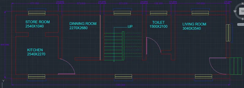
. GROUND FLOOR PLAN :
. procedure :-
. take command : XL
. draw horizontal line and vertical line
. take distance 230 mm through offsert command
. distance 2540x1040
. for kitchen
. offset 2540x2270
. gives 230mm offset
. command TR and trim the extra part of lines
. for dinning room
. take offset 2500x2880
. again offset 230 mm wall thickness
. for staircase
. distance : 2270 and 230
. take distnace of rise 200 and treds
. for toilet
. take distance 1500x2100
. take distance 230 mm as wall thickness
. for doors and window
. commance rec
. command circle
. maake 2 point circle
. trim extra point
. for window put object snap on
. take offset of the line distance 1000
. take centre point of that line and marks 2 horizontal line by using offset command
. command line type
. take iso dash
. command DIMLIN for dimenssion
. give the dimenssion
. command DIMCINTINUE
. give the all the dimension for units
. command MTEXT
. give the text
. go to the layer proprty
. create layer
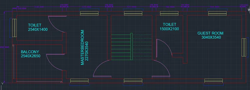
. FIRST FLOOR PLAN :
. PROCEDURE :-
. Command : xl
. make the horizontal and vertical line
. command offset and give 230mm offset for wall thickness
. for toilet
. use offset command
. dimension : 2040x1400
. command offset and makke 230mmm thickness of wall
. for balcony
. command offset
. take distance 2024x2650
. marks 230 mm offset for wall
. trim extra lines
. put object snap mode on
. an d marks the balcony portion
. command : circle
. draw the circle
. for masterbedroom
. command offset
. take distance 2600x3640
. take 230mm wal thickness throgh offset
. trim the extra part of the lines
. for staircase
. command offset
. take disstance 2270x230
. object snap on
. take midpoint of lines 2270
. marks the vertical lines
. give the offset having distance 100mm for the vertical lines
. distance of rises and treds 200mm
. click on multiple
. take 9 no of offset lines
. command : line type
. select line type ISO dash
. put it curent
. command offset
. distance 200 select multiple
. trim extra lines
. for toilet
. command offset
. distance 1500x2100
. gives 230 mm offset of wall thickness
. trim the extra part of lines
. for master bedroom
. take distance 3110x3540
. give the 230 mm offset
. for window put object snap on
. take offset of the line distance 1000
. take centre point of that line and marks 2 horizontal line by using offset command
. command line type
. take iso dash
. command DIMLIN for dimenssion
. give the dimenssion
. command DIMCINTINUE
. give the all the dimension for units
. command MTEXT
. give the text
. go to the layer proprty
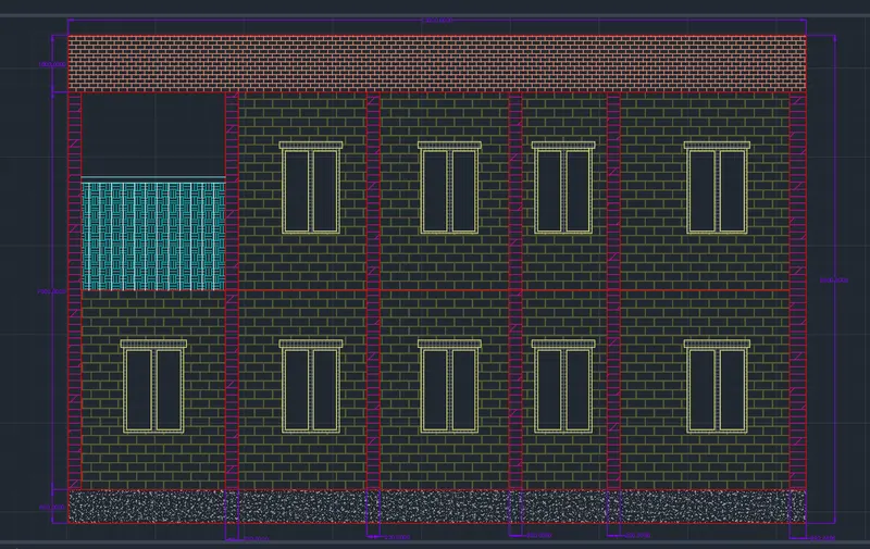
. ELEVATION
. PROCEDURE :-
. comand xl
. marks horizontal line and vertical line
. command offset
. distance 13300 and vertical distance
. command offset
. take the distance horizontally
. then give thre offset at distance 3500
. again gives offset distance 3500
. then give 1000 for parapet wall
. command tr
. trim the extra lines
. take the refence line for window and balcones from ground floor plan
. command rec
. click on dimenssion
. length 1400
. width 120
. this rectangle paced over window
. command rec
. click on dimenssion
. lengh 1000
. width 1975
. command rec
. length 400
. width 1870
. this rectangle use command mirror
. put object snap on
. select midpoint and mirroe the object
. command hatch
. hatch setting
. apply hatch to all window
. for doors
. marks the referance line from ground floor plan
. command rec
. select start point
. click on dimenssion
. length 1200
. width 2300
. take offset at distance 50
. select the rectangle
. mark the internal offset of rectangle
. for parapet wall
. coomand rec
. select starting point
. click on dimenssin
. length 250
. width 500
. mark the horizontal 2 lines eith referance to this rectangle
. cooamne AR
. click on path
. select object
. click the horizontal lines
. no of object is array is 9
. command tr
. trim extra lines
. give the hatch
. for the balcony
. mark the lines referance to ground floor plan
. command tr
. trim the extra lines
. gives the hatch portion
. command DIMLIN
. give the dimenssion
. command MTEXT
. give the text to the plan
. section plan
. procedure
. take the referance lins of first floor plan vertically
. command L
. marks horizonntal lines and vertival lines
. command O
. offset ditance at 1000
. then mark 150mm offset lines horizontally
. then marks 3000 mm offset lines
. then 3000 mm offset lines
. marks the 150mm offset lines horizontally by using offset command
. then mark the 600mm offset by using offset horizontally
. command tr
. trim the extra lines
. then marks the window by projecting the window from the the first floor plan
. for window
. command rec
. click on dimenssion
. legth 1000
. wiidth 1745
. again command rec
. click on dimenssion
. length 420
. width 1645
. placed this rectangle in larger rectangle
. command MR
. put object snap on
. click on midpoint
. gives mirror this object
. command hatch
. give the hatch
. command breakline
. put object snap on
. marks the line over wall section
. click on midpoint
. and the break the line
. for column
. command rec
. select the starting point
. click on dimenssion
. length 230
. width 400
. command hatch
. given the hatch portion
. command DIMLIN
. give the dimenssion
. command DIMCONTINUE
. give the command MTEXT
. give the al text
. go to the layer properties
. create new layer
. give the proper layer properties
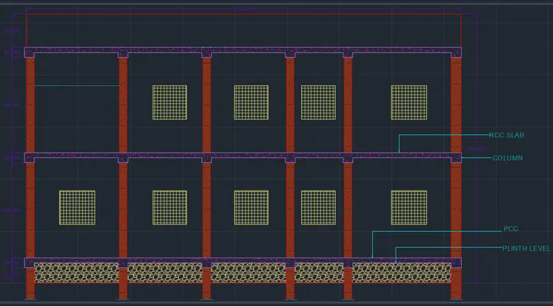
. COLUMN LAYOUT PLAN
. PROCEDURE
. Take the refrance line of ground floor plan
. the go the line type
. select the ISO dash short dash line
. make it current
. go to the annotation tab
. click on line portion
. click on centre line
. and marking the centre line
. trim thr outer line of the wall
. command tr
. trim the outer parts of the portion
. command rec
. click on the point where column is placed
. click on dimenssion
. length 230
. width 400
. in this way palced all column where required
. command hatch
. and give the hatch to the all columns
. command DIMLIN
. give the dimenssion
. command DIMCONTINUE
. command MTEXT
. write all the text in plan as shown in figure
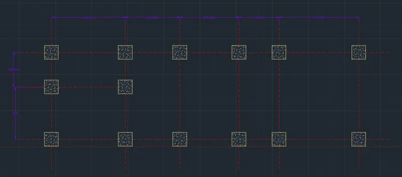
. BEAM LAYOUT PLAN
. PROCEDURE
. Take the referance lines of ground floor plan
. command tr
. trim the extra lines
. go to the annotation tab
. click on centre line over plan
. for beam
. command rec
. take dimenssion
. length 230
. width 250
. and placed all beam over plan
. go to annotation tab
. click on leaders
. select modify option
. click on content
. select block option
. source block is circle
. gives the nos of all beams in plan as shown in fig
. command MTEXT
. write the text and gives the numbers to beam
. give the dimension
. go to the properties
. create new layer and use it
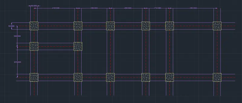
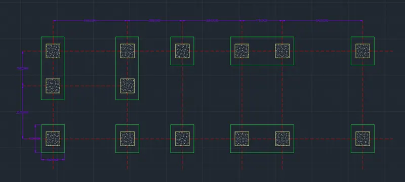
. FOOTING LAYOUT PLAN
. PROCEDURE
. Go to the line type
. click on load
. click on centre 2 line
. make it current
. take the referance line of ground floor plan
. command trim
. trim the extra line
. go to annotation tab
. click on the centre line
. give the centre line
. trim the outer line
. command rec
. select point where the rectangle is required
. click on DIM
. length 30
. width 400
. for ffoting
. command offset
. offset at a distance 500
. command dimlin
. give the dimenssion
. command dimcontinue
. give the all the dimenssion to the plan
. command MTEXT
. write the text