Creating a Floor plan, Footing detail and Isometric view using AutoCad
Challenge 2 :
AIM & INTRODUCTION :- TO create geometric of the folliwing using Auto CAD .
. Cross section of load bearing wall over spreding footing
. Cross section of isolated footing
. Line diagram of a two bedroom building
. Cross section of load bearing wall showing details
. Isometric view of steps
. Isometric view of grable wall
PROCEDURE :-
Initial settings :
- Open auto cad > advanced setup > units : decimal & precision 0.00 > Angle : decimal degree & precision
> Angle measure : East > angle direction : counter clock wise > Area : 420 x 297
- ( Template - Imperial )
Note :- Press ENTER after each command
1:- To draft C1 ( Cross section of load bearing wall over spread footing )
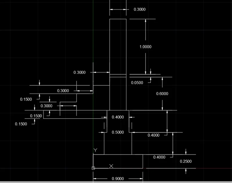
. choose rectangle tool
. rectange specify first corner point : 0,0
. specify other corner point : D
. specify length for rectnagle : 0.90
. specify width for rectangle : 0.25
. Press ENTER
. choose line tool
. specify first point : put cursor at top left corner of rectangle size 0.90,0.25
. speficy next point : @0.20,0
. specify next point : @ 0,0.40
. specify next point : @0.05,0
. specify next point : @0,0.40
. specify next point : @0.05,0
. specify next point : @0,0.60
. specify next point : @0.30,0
. specify next point : @0,-0.60
. specify next point : @0.05,0
. specify next point : @0,-0.40
. specify next point : @0.05,0
. specify next point : @0,0.40
. Press ENTER
. choose line tool
. specify first point : PUT down cursor left top corner of rectngle of size 0.30,0.05
. specify next point : @0,0.05
. specify next point : @0.30,0
. specify next point : @0,0.05
. Press ENTER
. choose line tool
. specify first point : put cursor at left top corner of rectangle 0.30 x0.60
. specify next point : @0,-0.15
. specify next point : @-0.30,0
. specify next point : @0,-0.15
. specify next point : @-0.30,0
. specify next point : @ 0,-0.15
. specify next point : @-0.30,0
. specify next point : @0,-0.15
. specify next point : @-0.30,0
. speficy next point : @1.15,0
. specify next point : @0,0.15
. specify next point : @0.35,0
. specify next point : @-1.20,0
. Press ENTER
2:- To draft C2 ( cross section of isolated footing )
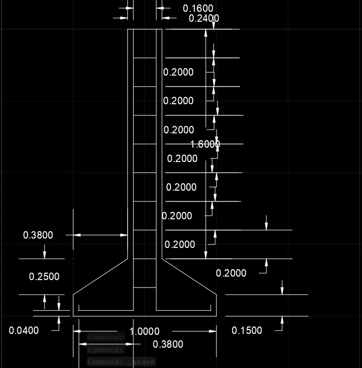
. Choose rectangle tool
. rectang specify first corner point : 0.5,0.5
. specify other corner point : D
. specify lenght of rectangle : 1
. specify width of rectangle : 0.40
. Press ENTER
. choose tool chamfer
. select first line or ( undo / polyline / distance / angle / trim / method / multiple ) : D
. specify first chamfer distance : 0.25
. specify second chamfer distance : 0.38
. select first line
. select second line
. Press ENTER
. command : TRIM
. select an object to trim : select object to trim is chamfer between second chamfer point
. Press Enter
. Command : line
. specify first point : put cursor at top of chamfer second corner point
. specify next point : @0,1.60
. specify next point : @0.24,0
. specify next point : @0,-1.60
. Press Enter
. command : OFFSET
. current setting : Erase source = no layer = source OFFSETGAPTYPE = 0
. speficy offset disatance : 0.04
. select object to offset or [ exit / undo ] :
. select point on side to offset or [ exit / multiple / undo ] :
. give the offset from left and right at distance 0.04 of the vertical line 1.60
. command : line
. specify first point : put cursor below line of left side of 1.60 OFFSET line
. specify next point : @0.16,0
. press ENTER
. command : OFFSET
. specify OFFSET distance : 0.20
. giving the total 8 offset of 0.20 distance at above and bottom
. Press ENTER
. command : line
. specify first point : put cursor at bottom of the left side 1.60 offset line
. specify next point : @0,-0.36
. specify next point : @-0.38,0
. specify next point : @0,-0.04
. Press ENTER
. command : line
. specify first point : put cursor at top of the right side of 1.60 offset line
. specify next point : @0,-.036
. specify next point : @0.38,0
. specify next point : @0,-0.04
3:- To draft C3 ( line diagram of a two bedroom building )
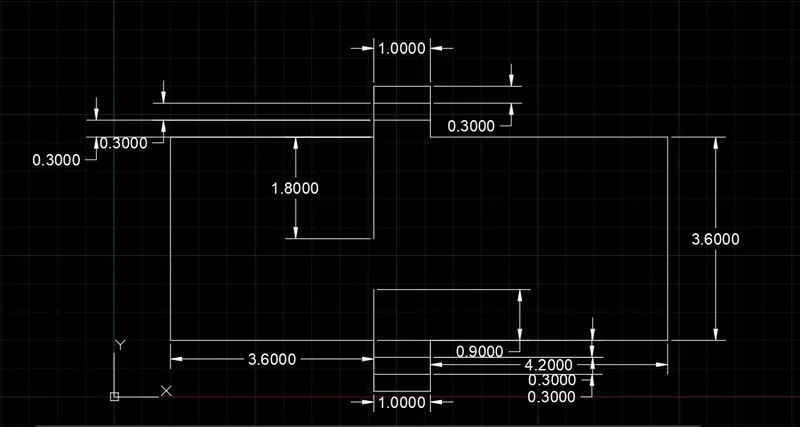
. command : line
. specify first point : 1,1
. specify next point : @0,3.60
. specify next line : @3.60,0
. specify next point : @0,0.30
. specify next point : @0,0.30
. specify next point : @0,0.30
. specify next point : @1,0
. specify next point : @0,-0.30
. specify next point : @0,-0.30
. specify next point : @0,-0.30
. specify next point : @4.20,0
. specify next point : @0,-3.60
. specify next point : @-4.20,0
. specify next point : @-0.90,0
. specify next point : @-1,0
. specify next point : @0,0.90
. specify next point : @-3.60,0
. Press ENTER
. command : line
. specify first point : put cursor on top of the 3.60 line at right side corner end
. specify next point : 0,-1.80
. Press ENTER
. specify first point : put cursor on bootom of the 3.60 line at the right side corner
. specify next point : 0,0.90
. Press ENTER
. command : OFFSET
. specify offset distance : 0.30
. offset enter layer option for offset object : current
. giving the offset of line length 1 at distance 0.30 of both top and botoom surface
3:- To Draft C3 ( C.S of load bearing wall )
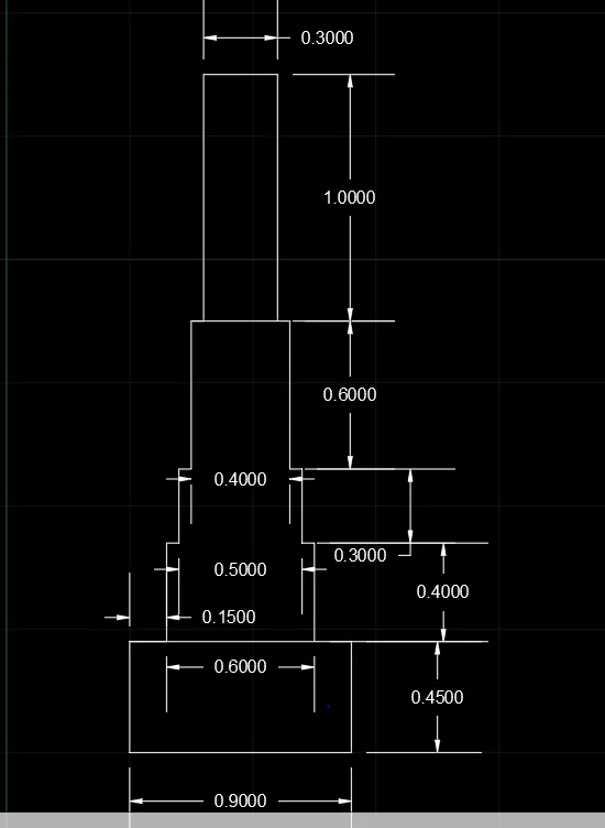
. Command : rectangle
. rectang specify first corner point : 0.5,0.5
. specify other corner point : D
. specify length for rectangle : 0.9
. specify width for rectangle : 0.45
. Press ENTER
. command : line
. specify first point : put cursor on the above of left side of rectangle 0.90 x 0.45
. specify next point : @0.15,0
. specify next point : @0,0.40
. specify next point : @0.05,0
. specify next point : @0,0.30
. specify next point : @0.05,0
. specify next point : @0,0.60
. specify next point : @0.40,0
. specify next point : @0,-0.60
. specify next point : @0.05,0
. specify next point : @0,-0.30
. specify next point : @0.05,0
. specify next point : @0,-0.40
. Press ENTER
. command : line
. specify first point : put cursor top of the drawing at left side
. specify next point : @0.05,0
. specify next point : @0,1
. specify next point : @0.30,0
. specify next point : @0,-1
. Press ENTER
3:- To draft C3 ( Isometric view of steps )
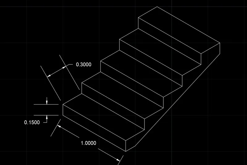
. command : DS
. settings > snap and Grid > snap type > isometric snap
. keep ortho mode on
. command : line
. specify first point : 0.5,0.5
. specify next point : < isoplane right > 0.15
. press Fn + F5
. specify next point : < isoplane left > 1
. specify next point : < isoplane left > 0.15
. specify next point : < isoplane left > 1
.press enter
. command : line
. specify first point : put cursor left of the drawing of above side
. specify next point : < isoplane to > 0.30
. specify next point : < isoplane left > 1
. specify next point : < isoplane left > 0.30
. specify next point : < isoplane left > 1
. press enter
. speficy first point : put cursor above of the left side of the drawing
. specify next point : < isoplane right > 0.15
. specify next point : < isoplane left > 1
. specify next point : < isoplane left > 0.15
. speficy next point : < isoplane left > 1
. press enter
. command : line
. speficy first point : put cursor above of left side of drawing
. specify next point : < isoplane right > 0.15
. specify next point : < isoplane left > 1
. specify next point : < isoplane left > 0.15
. specify next point : < isoplane left > 1
. press enter
. command : line
. specify first point : put cursor above of left side of the drawing
. specify next point : < isoplane top > 0.30
. specify next point : < isoplane left > 1
. specify next point : < isoplane left > 0.30
. specify next point : < isoplane left > 1
. press enter
note :- above alternate command completing the drawing upto 5 steps
. command : line
. specify first point : put cursor below of the drawing at the right side of drawing
. specify next point : < isoplane top > 0.15
. press enter
. command : line
. specify first line : put cursor above of right side of the drawing
. specify next point : < isoplane right > 0.15
. press enter
. specify first point : put below of right side of the drawing of line draw 0.15
. specify next point : put cursor above of right side of the drawing of draw line 0.15
6:- To draft C6 ( Isometric view of gable wall )
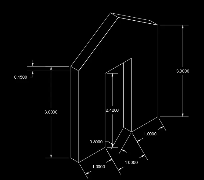
. command : DS
. settings > snap and Grid > snap type > isometric snap
. keep ortho mode on
. command : line
. specify first point : 1,1
. specify next point : < isoplane left > 0.15
. specify next poit : < isoplane left > 3.0
. specify next point : < isoplane left > 0.15
. specify next point : < isoplane right > 0.30
. press enter
. command : line
. specify first point : put cursor below right corner of the drawing
. specify next point : < isoplane right > 1
. specify next point : < isoplane right > 2.42
. specify next point : < isoplane right > 1
. specify next point : < isoplane right > 2.42
. specify next point : < isoplane right > 1
. specify next point : < isoplane right > 3
. specify next point : < isoplane left > 0.30
. press enter
. command : line
. specify first point : put cursor mid point of the drawing of line
. specify next point : 1
. specify next point : joining upper portion of the dreawing of top corner of left and right
. press enter
. select upper line of the drawing
. command : copy
. specify the base point : put line parallel to the copy line below 0.30 distance
RESULT :- above all the draft are creat using diffrent command to draft the easily . command use for above draft is line
isoplane , copy , offset , fillet , trim , etc