Project 1 _Creating an Architectural plan for the provided plot size and develop relevant basic structural drawings
AIM:-
- To draw an Architectural plan for the provided plot size and develop relevant basic structural drawings
A] Architectural Drawing
- Plan of a residential building
- Elevation of a residential building
- Section of a residential building
B] Structural Drawing
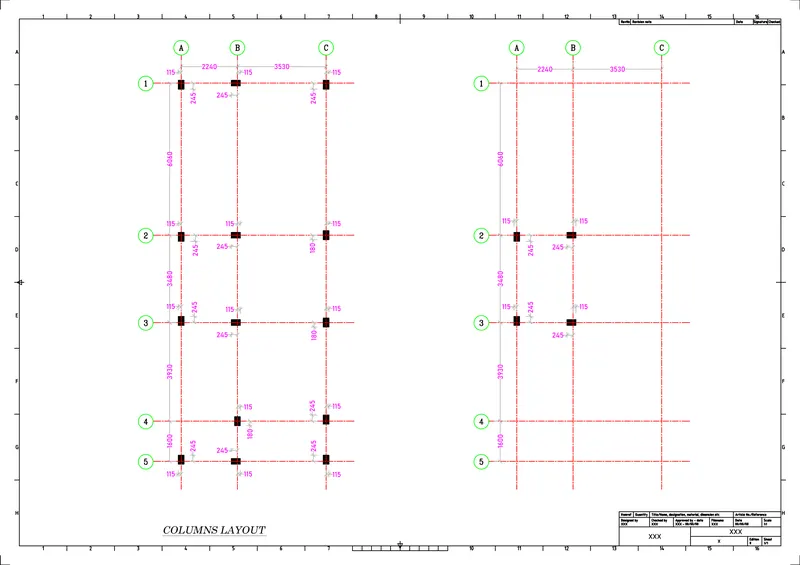
- Column plan layout of the building
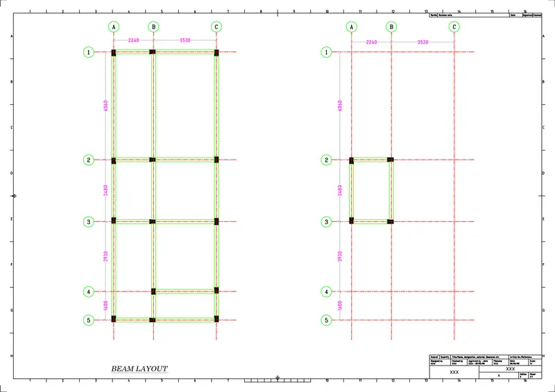
- Beam plan layout of the building
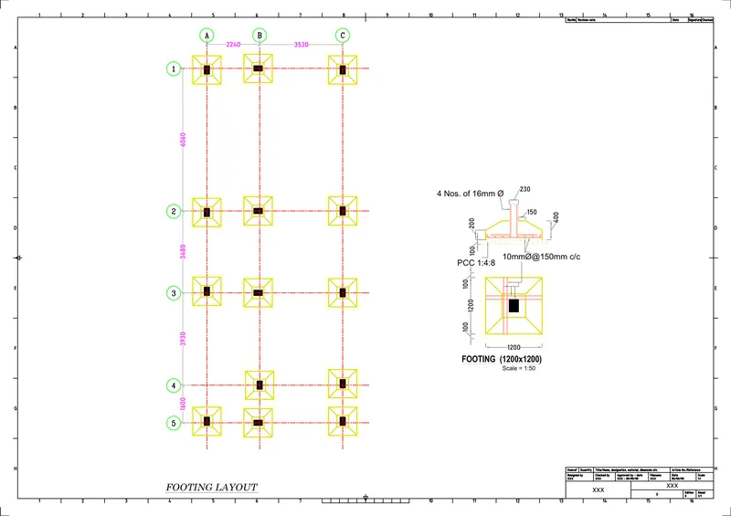
- Footing plan layout of the building
INTRODUCTION:-
- The buildings are planned based on the site availability and site condition, and it always obeys building rules in that region.
- An architect’s efficiency is utilizing maximum space in the given area.
- The first stage of designing the building is drafting a floor plan.
- For the finished look of the building, we have to draft the elevation of the residential building.
- Section of a building is also important for a better understanding of each component.
- The structural drawing is a set of plans that shows how a building structure will be built.
- It includes foundation details, framing details, columns, and beam details.
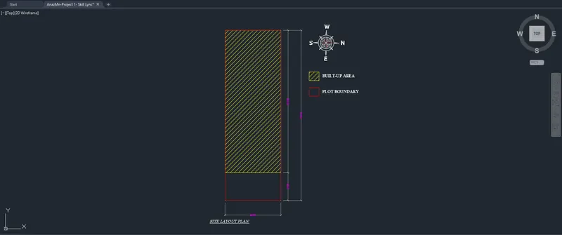
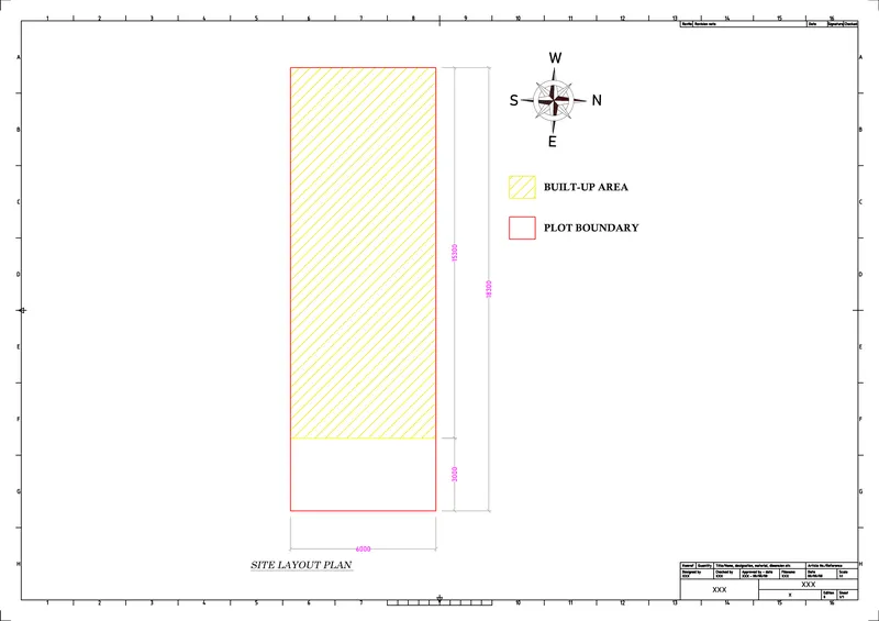
- The proposed residential plan has east facing orientation and the plot size is 18300mmx6000mm.
- The drawings provided are floor plan, elevation, section, column layout, beam layout, and footing layout.
COMMANDS USED:-
- Unit
- Limit
- Layer
- X-line
- Line
- Offset
- Trim
- Fillet
- Hatch
- Block edit
- Dimension
- Rectangle
- Circle
- Erase
- Copy
- Mirror
- Extend
- Move
- Rotate
- D-text & M-text, etc
PROCEDURE:-
A] Architectural Drawing:-
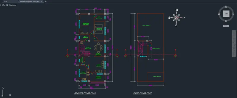
1. FLOOR PLAN
- Open AutoCAD new file
- Set the units as decimal-millimeters
- Set the required limits for the work
- Create new layers by command layer> like external walls, internal walls, columns, beams, windows, doors, dimensions, text, etc.
- Start the drawing by command rectangle and create the compound wall of plot size 18300 and 6000mm
- The building is east facing building
- Provide north direction
- Give setback as mentioned in the rule
- From the given outline we have to develop a plan.
- Offset the outer wall thickness of 230mm and the inner wall thickness to 150mm
- Trim the unwanted portions
- For the staircase, the tread is 250mm, the riser 180mm, width is 1000mm
- Create an opening for doors
- Create the door and block editor
- Place the door in appropriate spaces
- Dimension the room sizes using the dim command
- Create text
2. FRONT ELEVATION
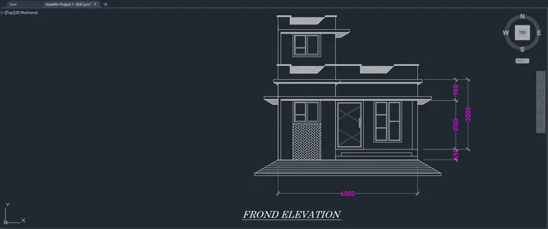
- Project the lines from the floor plan using Xline
- Draw a horizontal line to represent it as ground
- Take the offset of 450mm from ground level to get the plinth level
- Now offset the 3000mm from the plinth line to get the height of the residential building
- Take an offset of 900mm to get the parapet wall
- Finish the project door height of 2100mm
- Window size is 1600x1600 mm
- Trim the extended line
- Give the dimension
3. SECTION
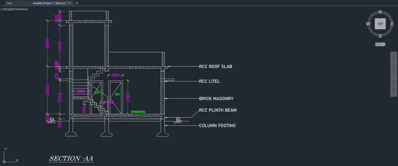
- Project the lines from the plan and elevation to get the dimensions of each component in the section
- Trim the unwanted lines
- Draw the staircase by cutting the section line, riser 180mm offset, and to the second flight take the riser and tread 250mm upto slab
- Finish the doors and windows from the projected lines
- Hatch the wall that is subjected to section
- Dimension the appropriates
B] Structural Drawing:-
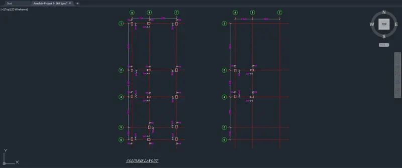
1. COLUMN LAYOUT
- Draw the center line throughout the wall and place the columns of dimensions 230mmx360mm in the corner of walls and intersections
- Delete the walls also and mark the gridlines in X and Y directions
- Provide dimensions
2. BEAM LAYOUT
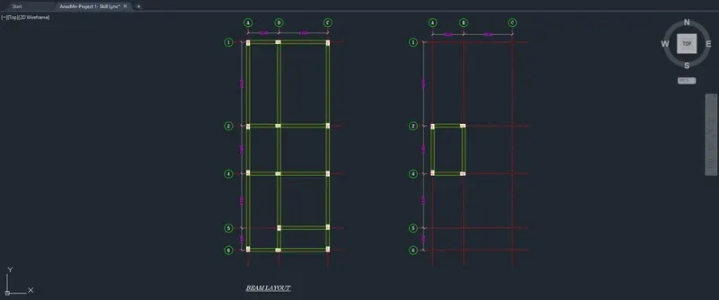
- Provide the beams by connecting the walls in the column layout
- The Plinth beam size is 230x450mm, First-floor beam size is 230x300mm
3. FOOTING LAYOUT
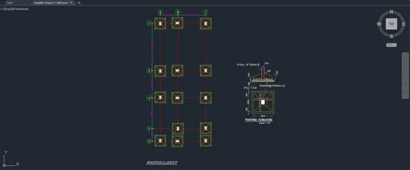
- Isolated and footings are provided
- Draw the rectangle of dimensions 1200 x1200mm and place it in the reference to the column layout
- Mark the dimension
RESULT:- Architectural and structural drawings are completed for the proposed residential building (All dimensions are in "mm" )
----------------------------X-----------------------------