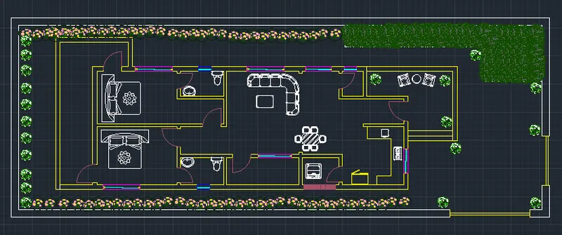
Project 1 _Creating an Architectural plan for the provided plot size and develop relevant basic structural drawings
Creating an Architectural plan for the provided plot size and develop relevant basic structural drawings
AIM:To create a residential building's architectural drawing, A residential building plan, A residential building's elevation, and A residential building section. A Structural drawing Building column plan layout. The layout of the building's footings. The building's beam layout. Line,... were used as commands.
APPARTUS: By using AUTOCAD software developing an architectural plan for the given plot size, as well as relevant basic structural drawings.
Commands used in this drawing: Line, offset, rectangale, trim, join, extend, block, mirror, angle, circle, arc, scale, LTS, Dimensions, Hatch, and Desing center
PROCEDURE:
Architectural drawing of a residential building:
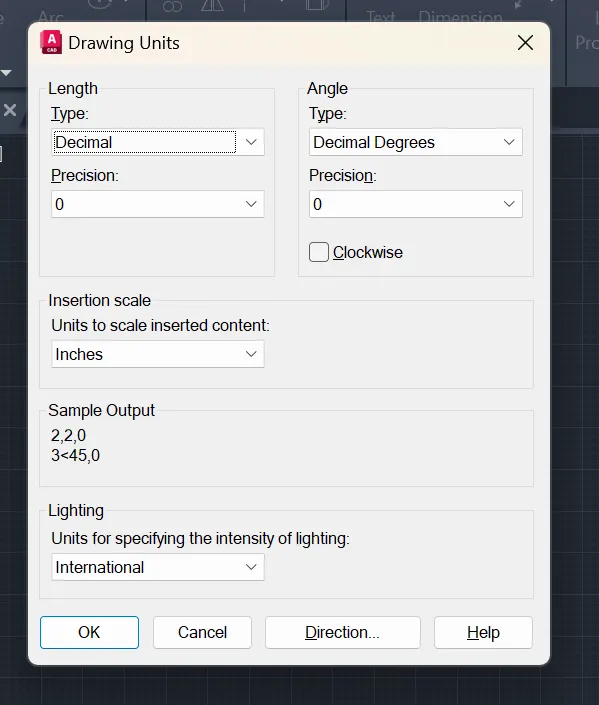
- Set the units to decimal meters and then Set the parameters and zoom in on everything. (Command -Z-a).Set the precision to one and the dimension to decimal units. Residential structure architectural drawing
-
Drawing the plot and giving setback. Given plot size as 18.3m x6m.Mark the direction N, S, E, W. By rectangle, draw the plot giving dimensions as 6 and 18.3 m.
-
Next give setback from the plot, 4.3m and 3m for the sides. The proposed building should come inside the setback drawn.
-
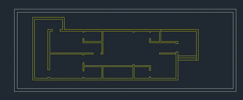
Drawing wall Offset 0.25 m from the boundary after the setback is taken for the wall thickness.
-
As the orientation is given as East, main door should face East.
-
As per Vaastu Shastra, North-East is favourable for living room and the entrance should face North or East.
- Living room = 19' X 18'
- Kitchen room = 10' x 10'
- Master bed room = 13' x 9'6"
- Bath room = 6' X 7'
- Bed room = 13' x 9'
- Bath room = 6' x 7'
- Puja room = 5' x 4'
- Balcony = 6' x 10'
- Utility = 6' x 8'
-
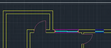
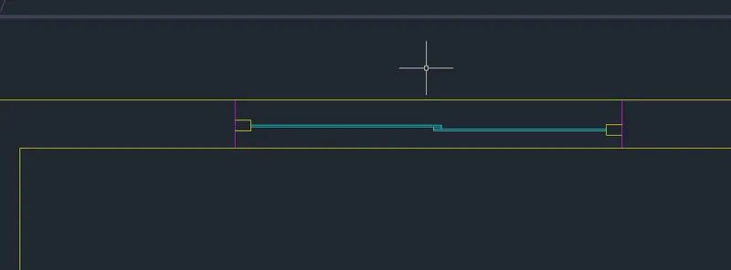
Place the doors and windows in their proper locations.
-
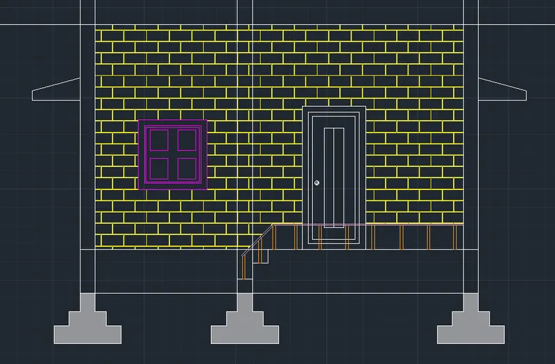
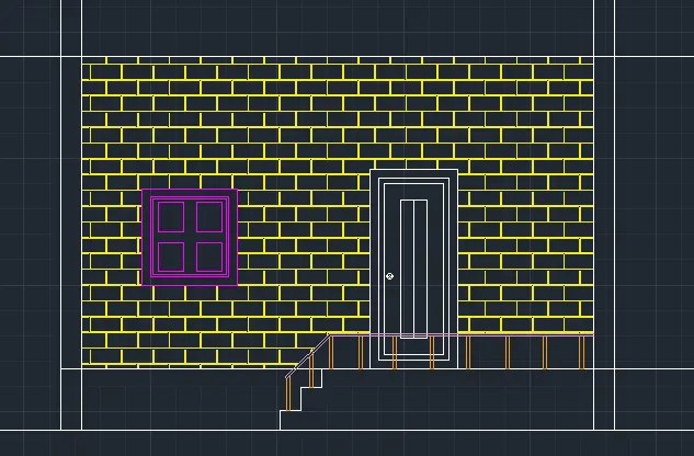
Elevation Drawing the elevation by projecting lines.Extend the wall lines to the ceiling.
-
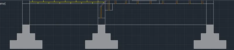
Make a horizontal line.Set the plinth level back 1 m.Lintel level offset is 2.1m.Offset the floor level by 3.5m.Offset the parapet wall by 0.6m.
-
Using the bricks hatch and the concrete hatch, hatch the walls and foundation.
-
Project the lines for the height from the elevation and the horizontal members from the section line of plan.
-
In section, draw windows, doors, and stairs.Remove the extension lines and create shutters and window panels.Make some hatches for architectural purposes.
-
For the height, project the lines from the elevation, and for the horizontal members, project the lines from the section line of plan.
-
Colorize the windows and foundations in their respective layers.
-
Create a sectional drawing of windows, doors, and stairs.Draw the window and door visible after the section line is cut.
-
Using the brick hatch and the concrete hatch, hatch the walls and foundation.

Structural drawings:
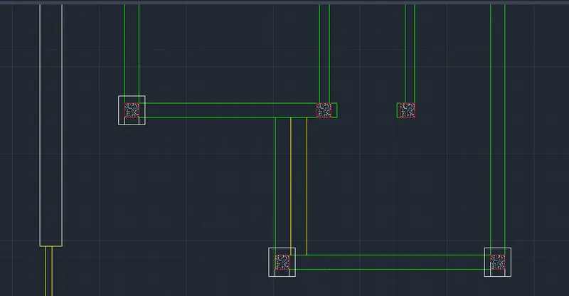
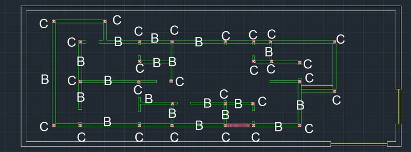
- Column layout: A 0.25m x 0.25m column is considered. Columns are placed in all corners of the wall and at wall intersections as needed.
- Draw the column centre line from the annotate tab -centre line and label the grid line as 1,2 in the y direction and A, B, C, D, E, F in the x direction.
- Footing Layout: A 0.5m x 0.5m isolated footing is provided. Make a 0.5x0.5 m rectangle and align the centre of the rectangle with the centre of the column.
- The plinth beam is drawn to connect the columns by a 0.25m wide beam, as the wall thickness is 0.25.A plinth beam is installed beneath all the walls.
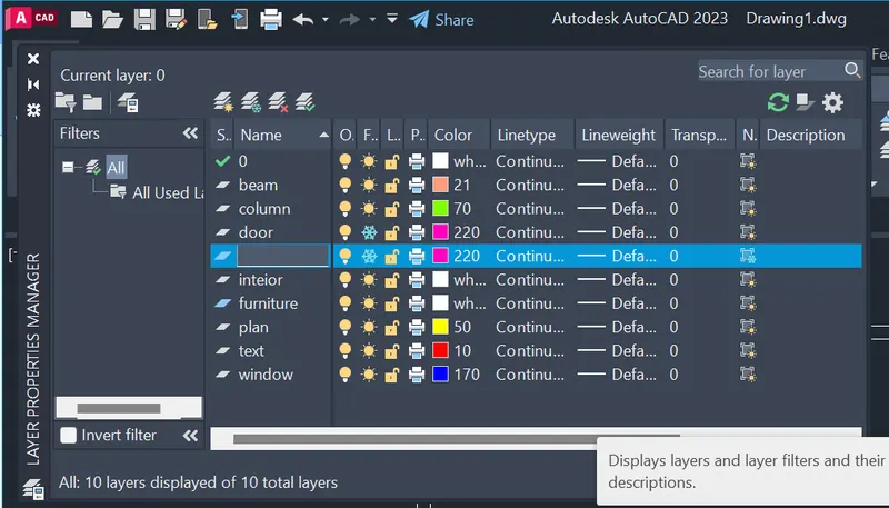
- Make a beam layer and place the plinth beam in it.
Result:
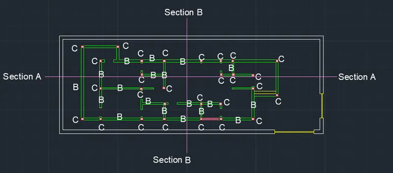
Section plan:
Elevation drawing:
Column and beam drawing:
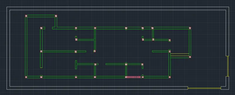
Final outcome:
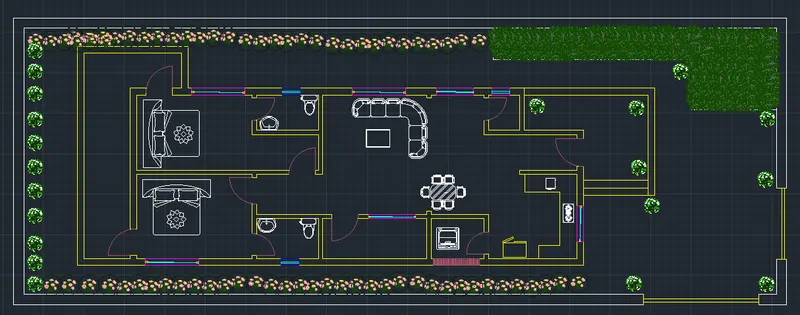
Result:
A residential building's architectural and structural plans are created.