Creating a Floor plan, Footing detail and Isometric view using AutoCad
Creating a Floor plan, Footing detail and Isometric view using AutoCad
AIM:
To Creating a Floor plan, footing detail and Isometric view by using AutoCAD.
INTRODUCTION:
The main purpose of this task is to access various AutoCAD tool such as, Rectangle, Circle, Line, Offset, Trim, Copy, Move, Dimension style, Snap mode, Ortho mode and Text. These commands are used to create a floor plan, footing details and isometric view of floor plan.
APPARTUS: Autocad
PROCEDURE:
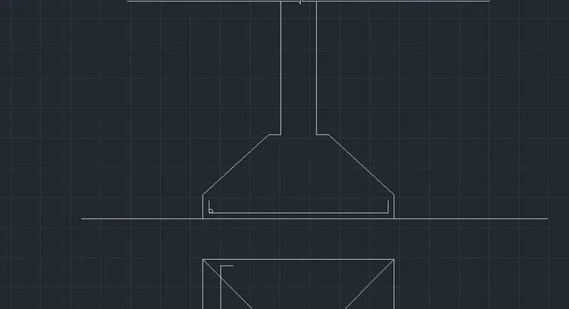
Cross section of load bearing wall over spread footing:
- Type Rec or Rectangle in the command line and press Enter.
- Enter dimensions of length of 0.90 and width of 0.25.
- Then type line command and specify the start point dimension of 0.2.
- Specify next point: @0.20, 0
- Specify next point:@0, 0.40
- Specify next point:@0.05,0
- Specify next point:@0, 0.40
- Specify next point:@0.05, 0
- Specify next point:@0, 0.60
- Specify next point:@0.30,
- Specify next point:@0, -0.60
- Specify next point:@0.05, 0
- Specify next point:@0, -0.40
- Specify next point:@0.05, 0
- Specify next point:@ 0,-0.40
- Type offset in the command and press Enter.
- Take distance of 0.05 above the line
- Type L in the command line and press Enter.
- Specify next point: @0, 1
- Specify next point:@0.30, 0
- Specify next point:@0,-1
- Type L in the command line and press Enter.
- Specify next point: @-0.30, 0
- Specify next point:@-0.05, 0
- Specify next point: @-1.15, 0
- Specify next point:@0, -0.15
- Specify next point:@1.15, 0
- Type L in the command line and press Enter.
- Specify next point: @0.30, 0
- Specify next point:@0, 0.15
- Specify next point: @0.30, 0
- Specify next point:@0, 0.15
- Specify next point: @0.30, 0
- Specify next point:@0, 0.15
- Specify next point: @0.30, 0
- Type L in the command line and press Enter.
- Specify next point: @1, 0
- Specify next point:@0, -0.60
- Specify next point: @-0.95, 0
- Now Trim the all the extra lines of the diagram.
- Give the dimensions as per the drawing using dimension command from the command bar.
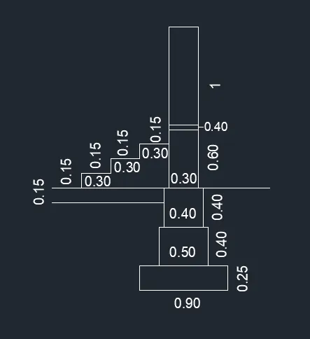
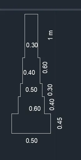
Cross section of load bearing wall:
- Create a REC in command box.
- Mention (5,5) point in the command box length 0.9 and width 0.45.
- Then again enter REC. specify the first corner point which is 0.15 units from the starting point of rectangle.
- Enter length 0.6 units and width of 0.4 units.
- Again create REC. Specify the first corner point which is 0.05 units from the starting point of second rectangle. Enter the length 0.5 and width 0.3.
- Fourth rectangle specify the first corner point which is 0.05 units from the starting point of second rectangle.
- Enter the length 0.4 and width 0.6 units.
- Next draw the fifth REC.
- Specify the corner point as the corner of fourth rectangle.
- Click on dimension give length as 0.3 and width 1 units.
- Now trim the extra lines.
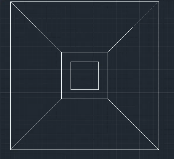
Isolated footing
- Draw the line command
- Type units makes it architectural change decimal.
- Select (10,0) starting point. XL for center line.
- Select offset tool 2 feet horizontal and vertical.
- Then trim the extra lines.
- Again select offset tool specify 6” inside the box. And join the lines at corner of the box.
- Now extent lines draw the vertical lines above the box.
- Draw a line horizontally.
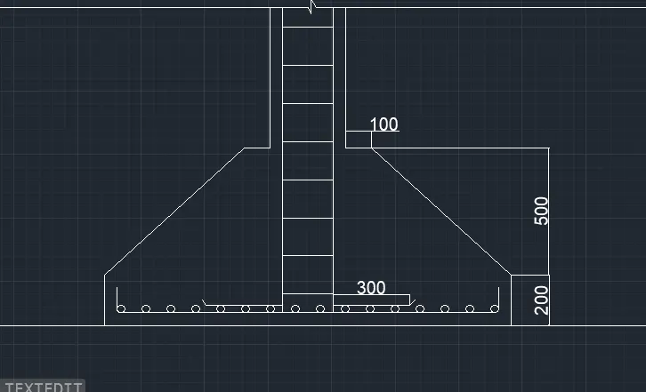
- Make sure that column size should be 300x 300mm.
- Footing height D= 500mm
- Base height d= 200mm
- And footing reinforcement = 16nos of 10mm dia both ways
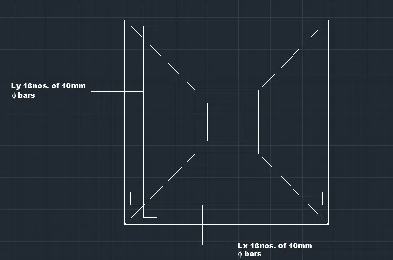
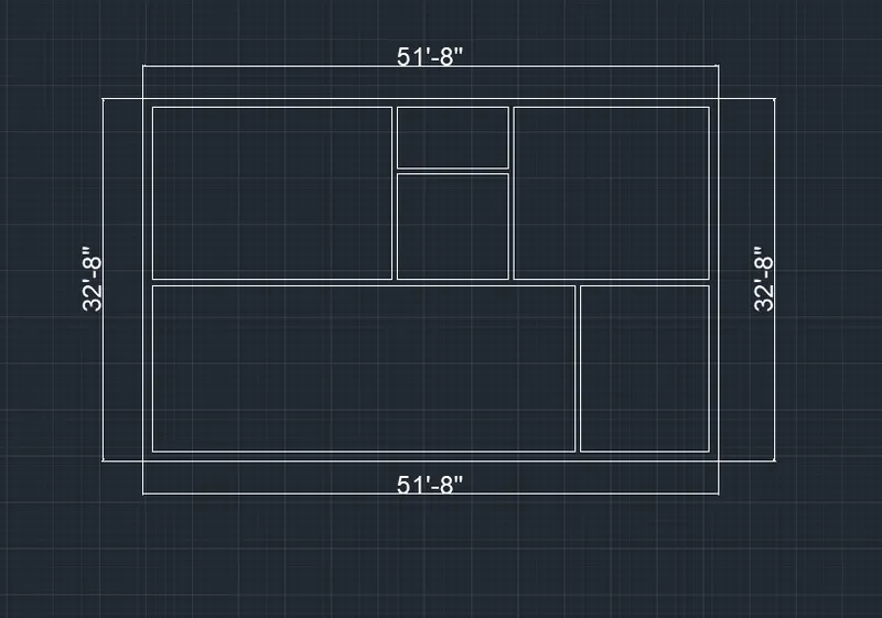
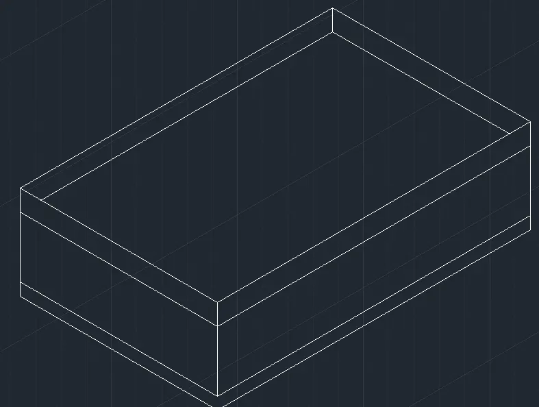
Isometric Plan:
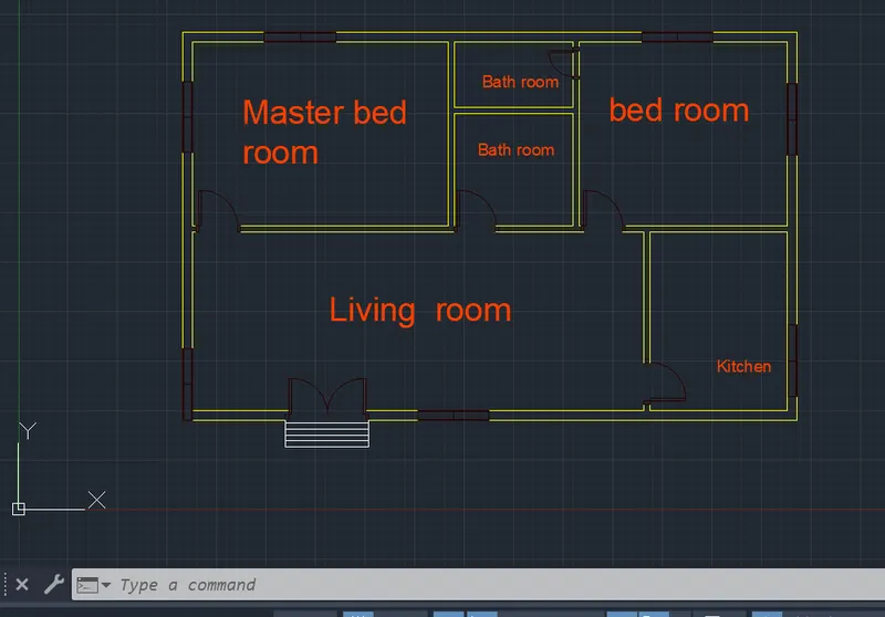
- Draw the floor plan by using AutoCAD.
- Select command length 51’8” and width 32’8”.
- Select offset of 10” draw inside the box.
- Draw bed room 17’6” x 15’6”
- Attached wash room 10’ x 5’6”
- Master bed room 21’6” x 15’6”
- Outside wash room 10’ x 9’6”
- Living room 38’ x 15’
- Kitchen 11’6” x15’
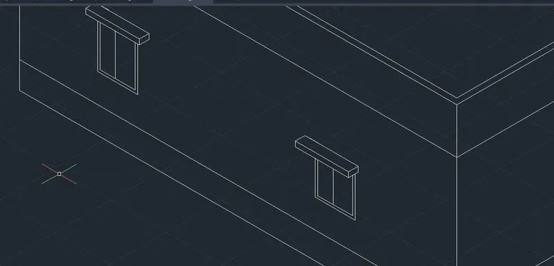
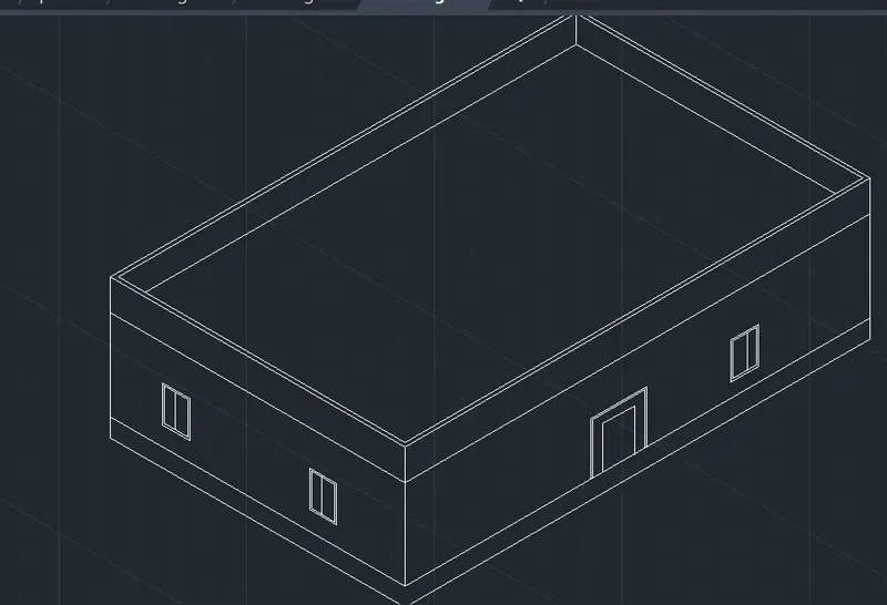
- After that draw the doors and window for the plan using REC command.
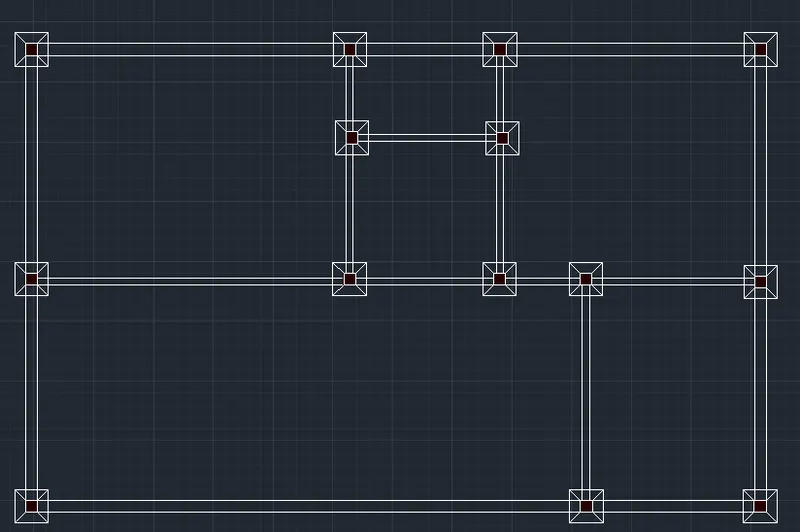
- After completion of floor plan. Copy the plan and draw isometric view of floor plan by using snap mode.
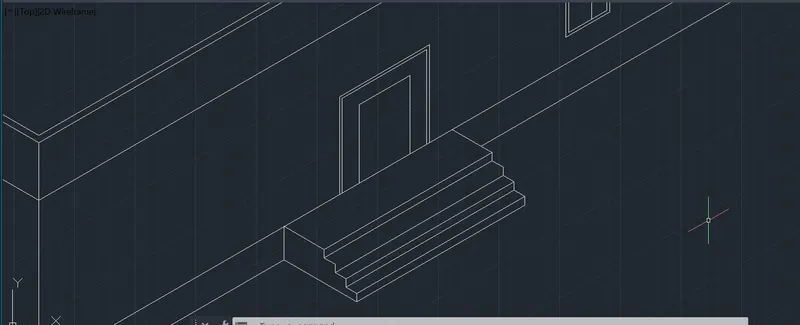
Result:
By using Autocad to create floor plan, footing details and isometric drawing while using Autocad. I use various tools like rectangle, polylines, dimensions, centre line, copy,move offset,chamfer,circle,trim,units,extend,join and snap mode and orthogonal mode.I had a good understanding of the tools and how to use it.