Creation of geometries by Coordinate system methods using AutoCad
Creation of geometries by Coordinate system methods using AutoCad
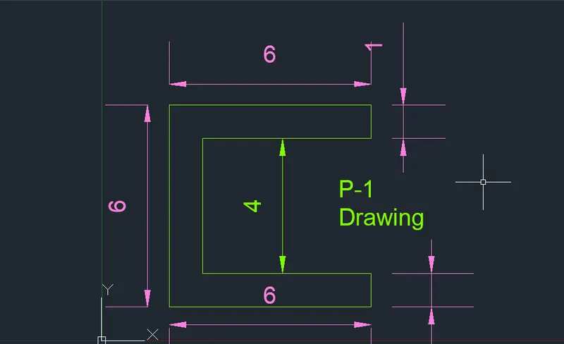
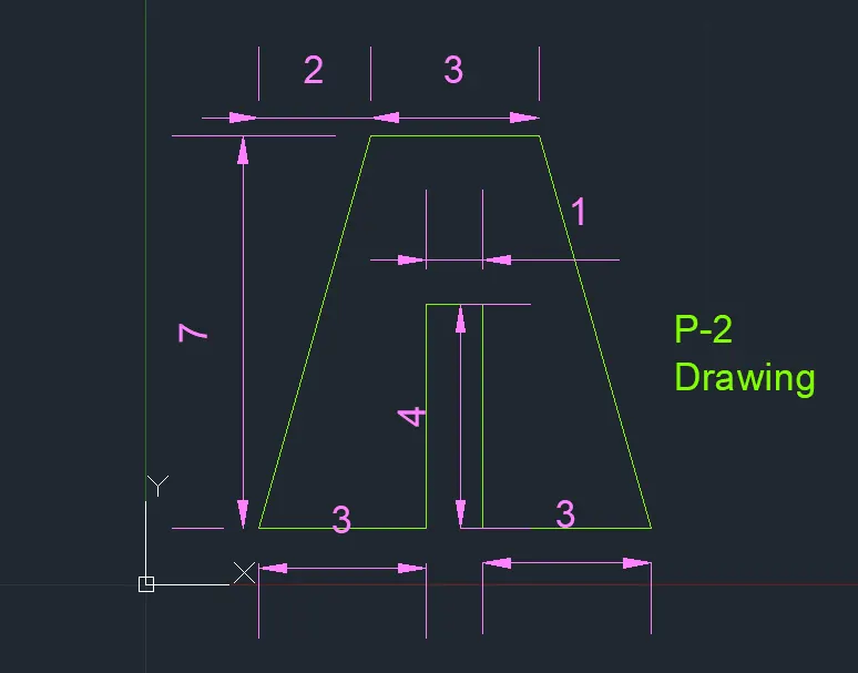
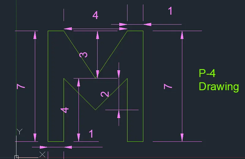
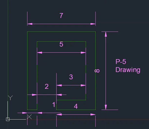
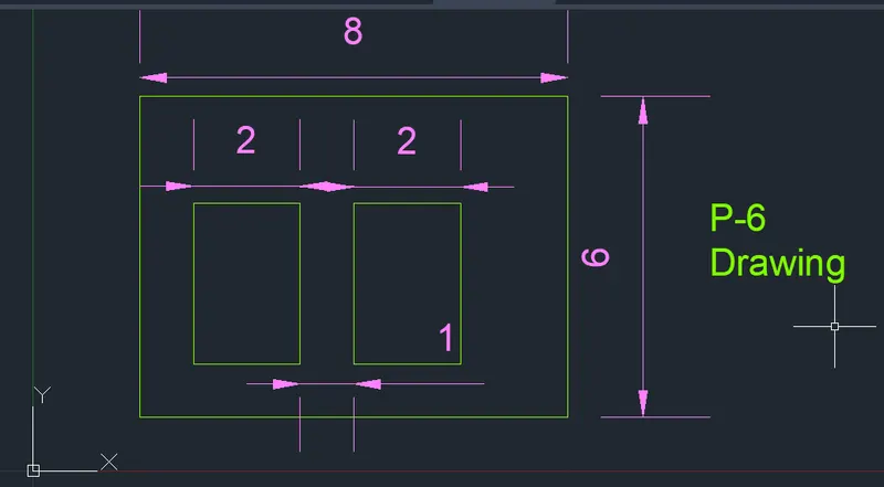
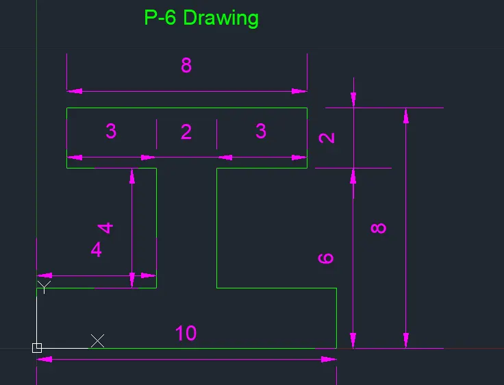
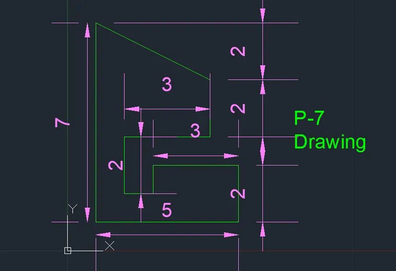
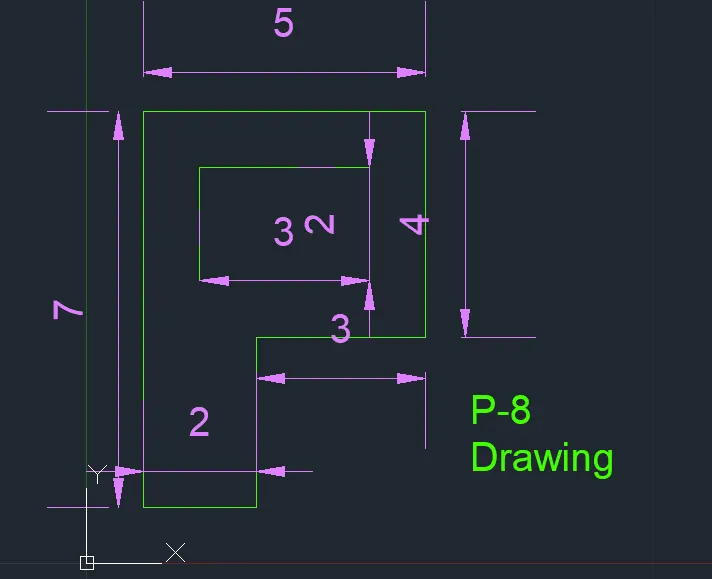
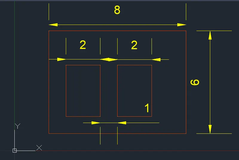
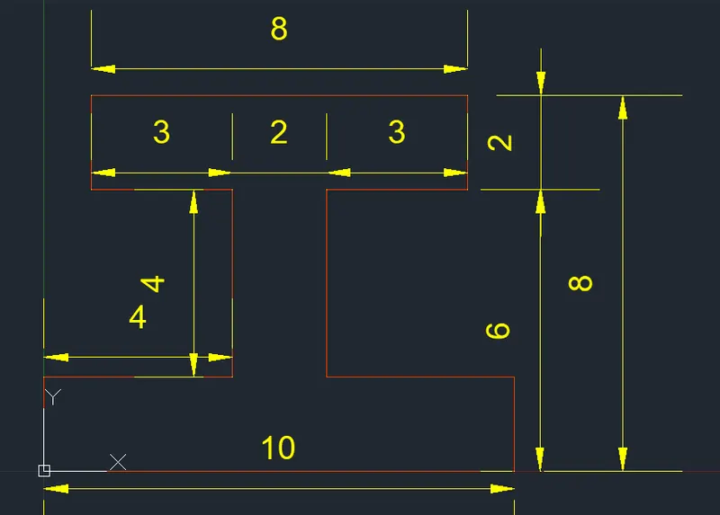
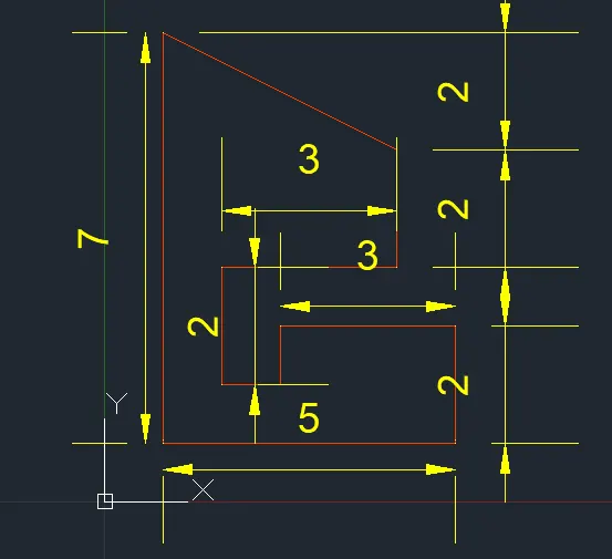
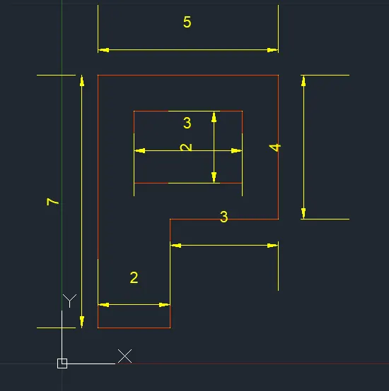
Task: Create the geometries from P1 to P2 using all the coordinates system methods. You need to use the Line tool to create the geometries. Where required you need to use the circle tool.
Please read the drawings and find out the missing dimensions before working on the sketches.
Note: Use the Imperial Template and the Decimal Units to draft the features. Dimensions are there for references.
Aim:
- To Create the geometries from P1 to P2 using all the coordinates system methods and P3 to P10 by any one coordinate system.
- To Draw the profile and the trusses using any coordinate system methods. The dimensions are there for reference.
Introduction:
Before going to the drawing, we should know about the coordinates systems.
- In AutoCAD there are two coordinate systems: Cartesian and polar.
- To these coordinate systems the absolute and relative coordinates of AutoCAD as are applicable.
Also coordinates in AutoCAD can be set by mouse, input (setting) the values of coordinates in the command line and enter coordinates using dynamic input.
There are three types of co-ordinate systems.
- Absolute coordinate systems
- Relative coordinate systems
- Relative rectangular coordinates
- Relative polar coordinates
- Direct distance entry
Commands used:
- Line command
- Dim linear command
- Text command
- Circle command
Procedure:
- Go to start menu select AutoCAD software file.
- Click on it and select new drawing.
- In the create new drawing, for 2023 version it have already mention a dialog box and imperial system in this option.
- After that, select decimal unit system
- Then set the limits by entering limits in the command tab. The lower left corner is specified as 0,0 and the upper right corner is specified as 100,100.
- Follow this procedure for every new drawing is to be created.
To Create the geometries from P1 to P2 using all the coordinates system methods:
Absolute co-ordinate system:
Relative rectangular coordinate system:
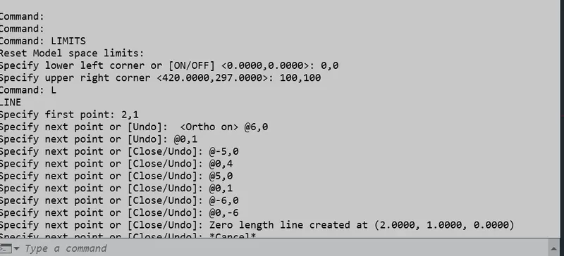
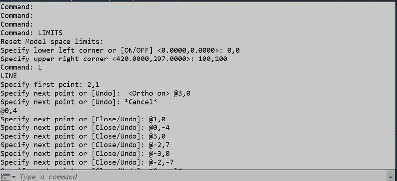
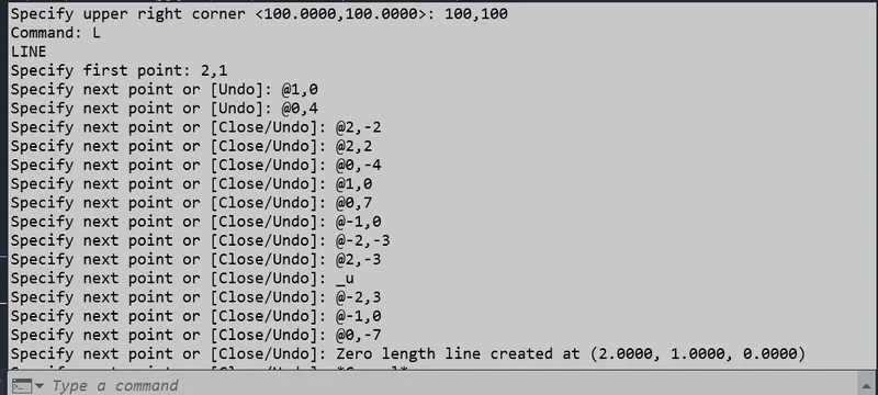
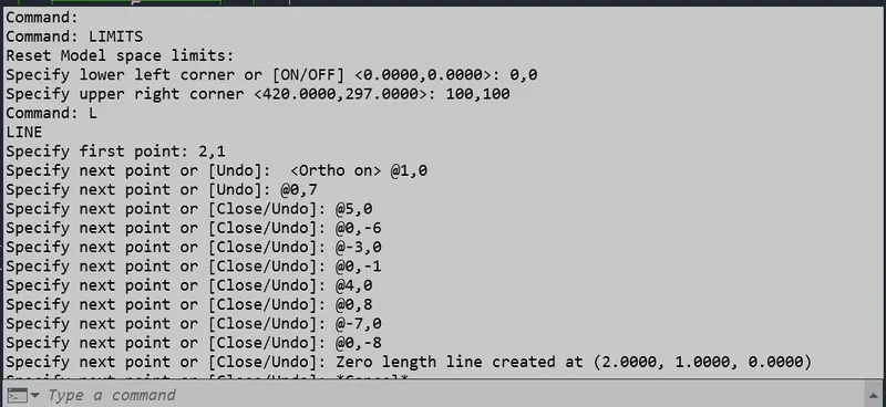
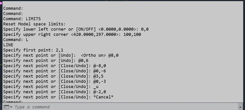
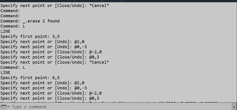
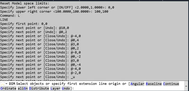
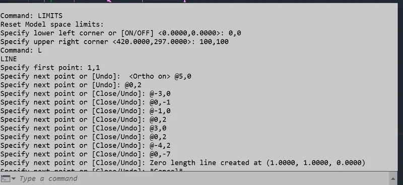
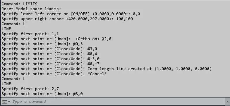
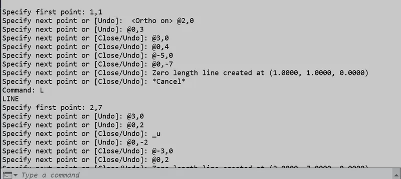
Relative polar co-ordinate system:
1.
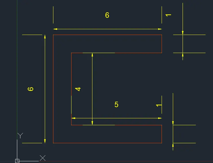
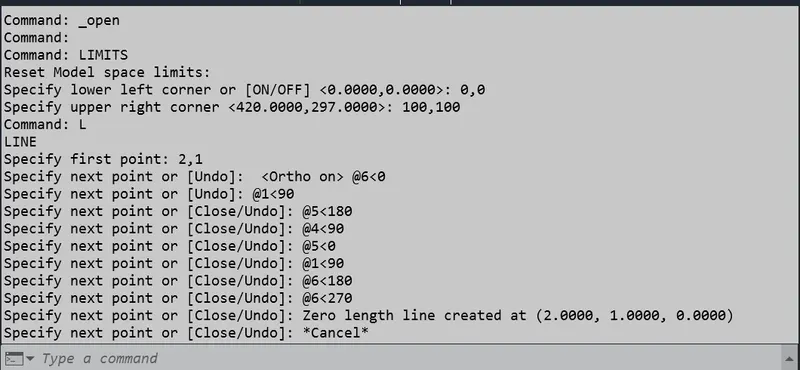
2.
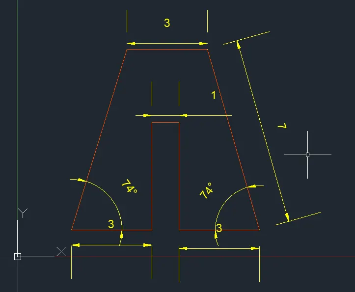
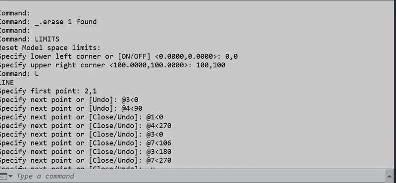
3. 4.
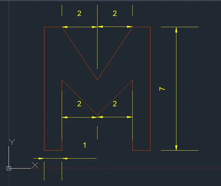
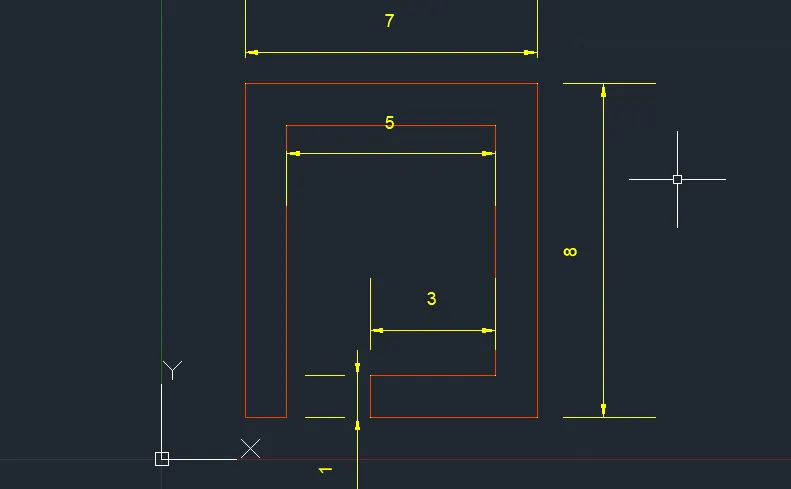
5. 6.
7. 8.
Direct distance entry:
Direct distance entry enables you to draw an object, such as a line, by pointing in a particular direction with the cursor and entering a distance at the command line.
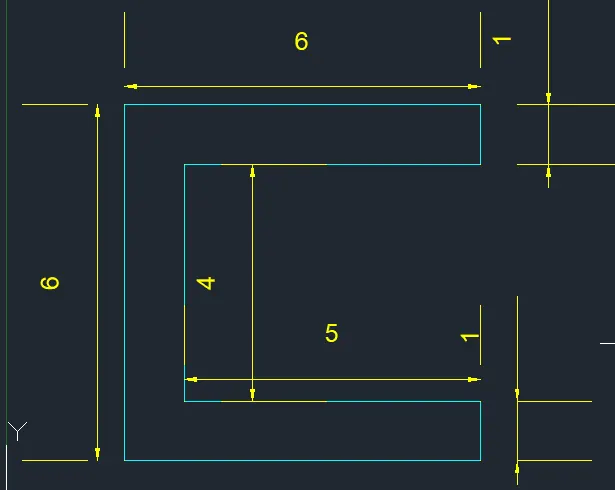
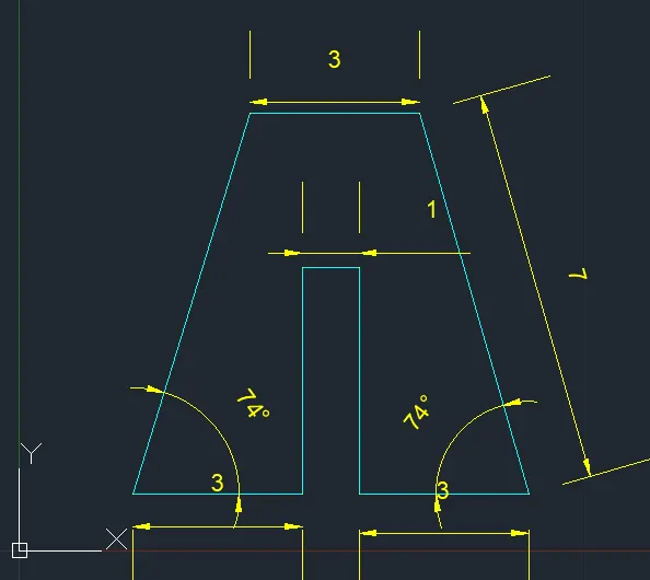
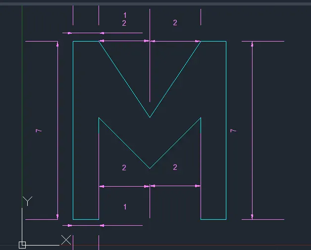
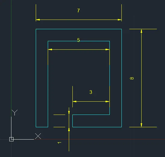
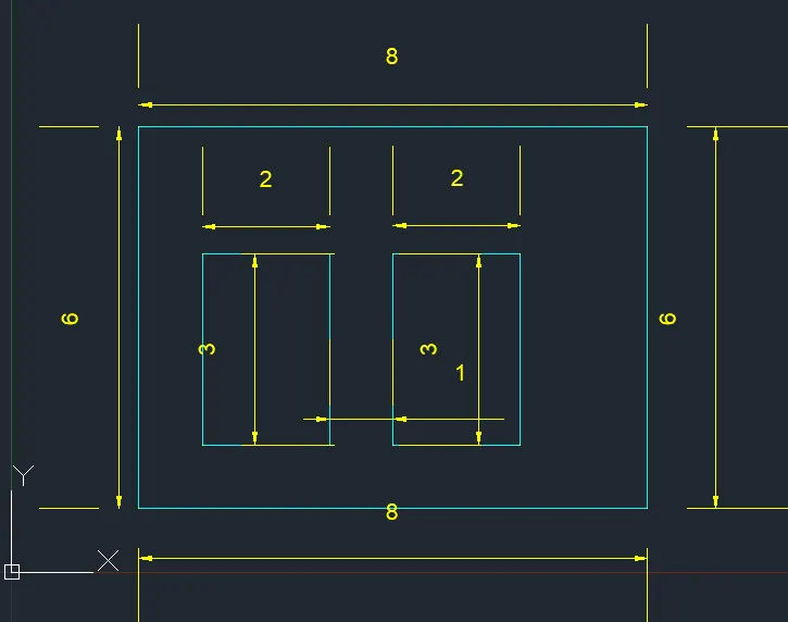
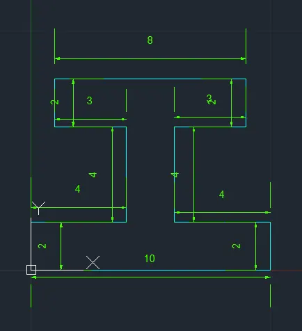
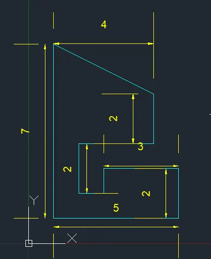
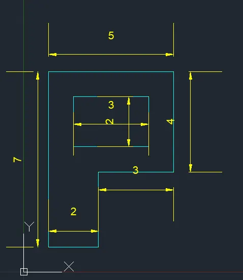
Civil related problems: Draw the profile and the trusses using any coordinate system methods. The dimensions are there for references.
By using Absolute coordinate system method:
Profile wood:
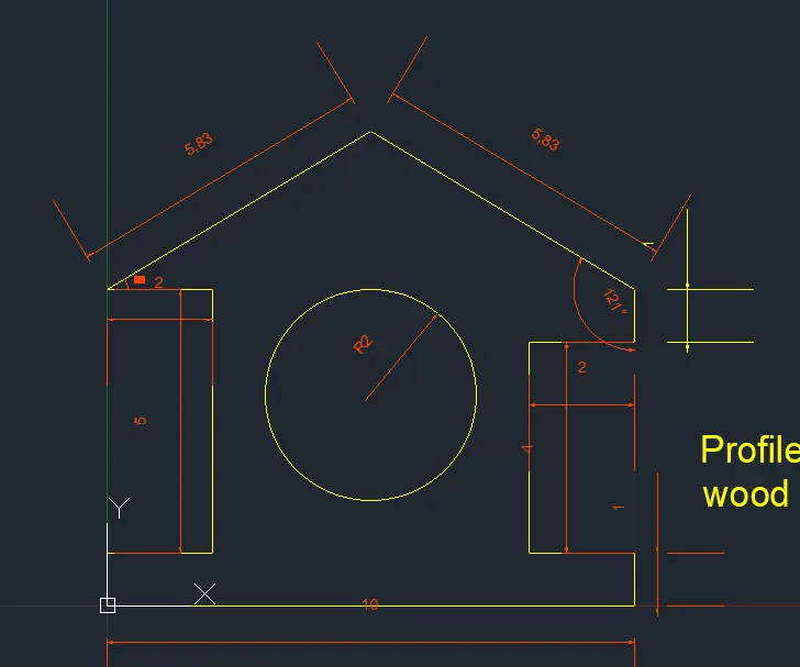
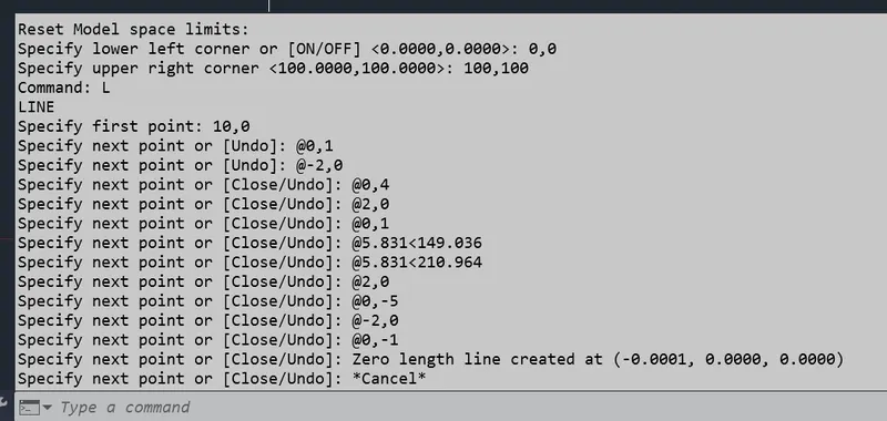
Then select circle command @ 5,4
radius of 2
Queen post truss:
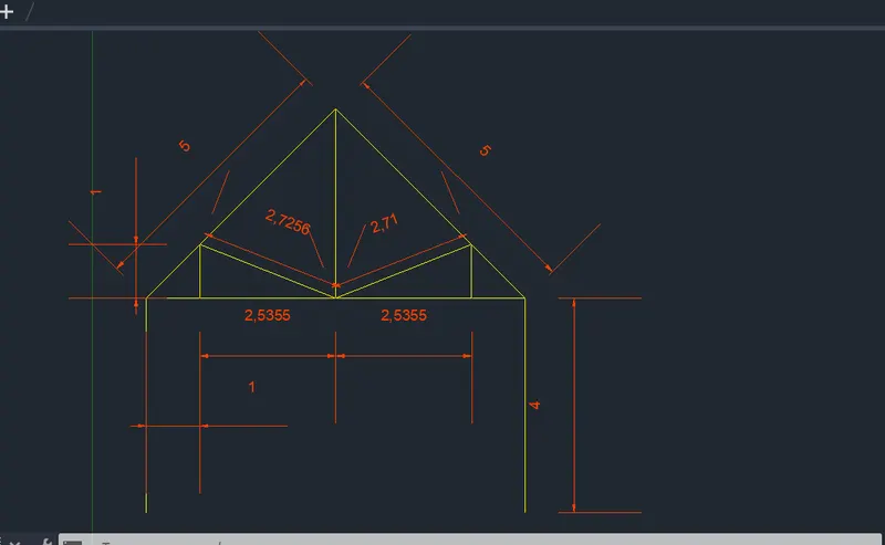
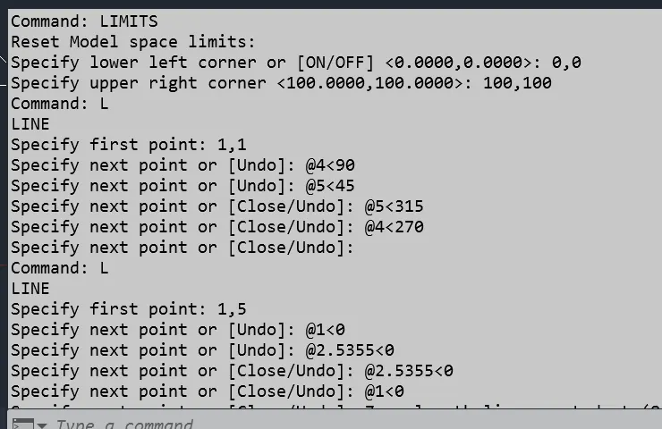
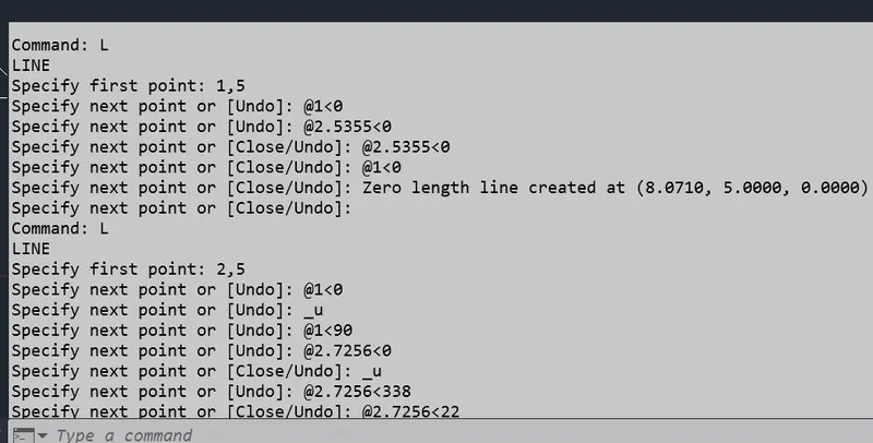
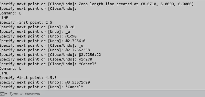
Mono pitch:
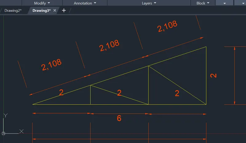
Result:
- Each graphic clearly identifies the geometries, and any missing dimensions are also noted.
- All of the drawings, from P-1 to P-8 pictures, are clearly produced using all of the coordinate systems.
- The absolute coordinate system method works well to draw the profile and trusses.