Project 1 _Creating an Architectural plan for the provided plot size and develop relevant basic structural drawings
Aim:
To Create an own architectural drawing consisting of floor plan , Elevation and section for the plot size 60'*20' and also create the structural drawing for column,footing and beam.
Introduction;
The aketched up in Autocad using various tools/commands.
1. Plote size-60'*20'
2.Orientation- East Facing.
Commands used:
* Layers
* Line
* Polyline
* Xline
* Dtext
* Multileader
* Dimlinear
* Dimcontinue
* Hatch
* Copy
* Fillet
* Trim
* Erase
* Offset
Procedure;
* Open Autocad
* Set the units to engineering and select ok.
* Set limits as lower left corner(0,0) and upper right corner (500',500')
* Go to layer properties< create new layers < name of the layers for reference< close.
* Architectural drawing;
1.Plan
2.Elevation
3.Section
* Structural drawing:
1.Column layout
2.Fooing layout
3.Beam layout
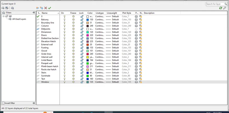
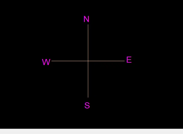
* Using the commands line and and Dtext, i have created the the directions.
* Then, using the block command, i made it to a single block and named it as directions.
I.Architectural Drawing;
1.Plan;
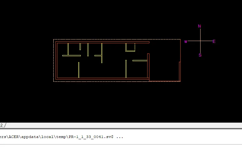
* Using the line command, i draw the plot boundary of 60'*20'.
* The buildings man entrance is facing, the east direction.
* Using the commands line, offset,fillet and trim.
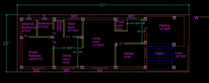
* starting from the east , the car parking is planed at 14'*10'6",lawn area for about 4'6"*8'8" and stairs for about 9'*9'
* The Building area is drawn leaving 1' offset distance in the north,west and south directions.
* After providing the offset distance ,the floor dimensions comes about 45'*18' including walls,
* Outer walls at 9" thickness and inner walls at 4.5" thickness is provided.
* I have changed the linetype into short -dash for the plot boundary and adjusted the scale for better visibility.
* Now , using the commands line, polyline,offset,fillet and trim, i have created my own plan for the project.
* It is planed as per VASTHU. Even those directions are mentioned below.
* Main door; East
* Stairs; South- East
* Kitchen: South-East
* Pooja room: North-East
* Living Area: Facingp- East
* Study room:North -East
* Dining room: South-East
* Master bedroom: South-west
* Attached Bathroom: North-west
* The room dimension are also assumed as per requirement.
* here, using the line and trim command, i have provied the door space as required.
* The door dimension are shown below in tabular form.
D1-5'*7'
D2-3'*7'
D3-2'6"*6'6"
* Using the mentioned dimensions doors are trimmed and placed and here is the figure attached below.
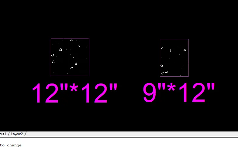
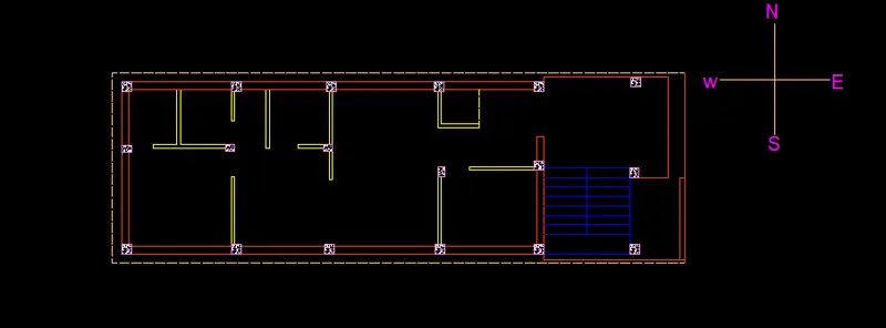
* Using line command,i have created column of sizes 12"*12" and 9"*12".using the hatch command ,ihave filled.
columns with AR-CONC and adjusted the scale for better visibility and copy pasted it whenever required in the floor plan.
* Stairs are provided using line and offset column,with tread-1' and rise 9"
* The window dimensions are shown below .
W1-5'*4'
W2-4'*4'
W3-3'*4'
V-1'6"*1'6"
* Windows are draw as per the dimensioned mentioned above and those are plotted and placed in the plan as per requirement.

* After placing the windows draw the sunshades.
* Using the Dtext command , i have mentioned the names for each rooms, space , doors, windows and the dimensions for all the rooms.
* Using the command line , offset , fillet, trim and Dtext, the compound entrance is crated with 6" thickness wall also the car parking and lawn area surrounded by 6" thickness compound wall.
* Using the DIM-LIN command, i have mentioned the dimensions in the additional space and change the layer to dimensions its colors for betterview.
* Using Hatch command, i have filled LAWN and adjusted the scale for better visibility
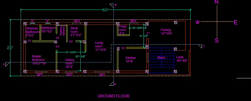
* Using the linetype LONG-DASH SHORT-DASH, i have cut the plan into 2 sections, Section-AA and Section-BB.
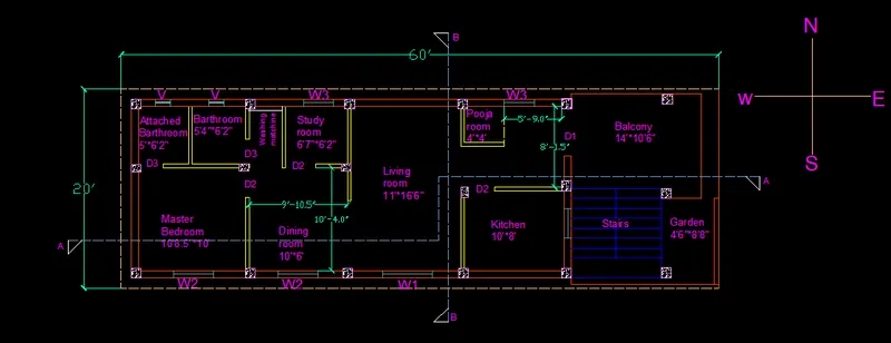
* And in the same way first floor is made only the change is parking is replaced as balcony as shown below.
2. SCTION_AA
* Using the command line,polyline ,offset, fillet and trim, i have createdthe sectional view for the Section-AA.
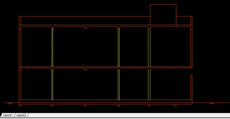
* Provided windows as per the plan, kitchen space as per plan and stairs as per plan.
* Provided lintel beam over the windows, doors.
* Provided parapet wall and over head as well.
* Using hatch command, i have filled PLINTH BEAM with BRICK and adjusted the scale for better visibility.
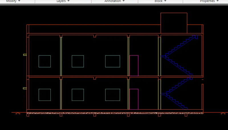
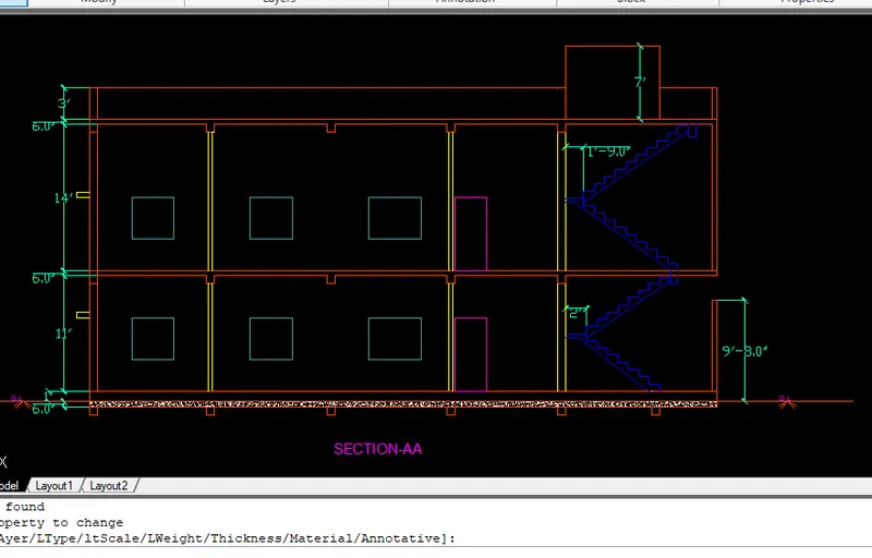
* Using the commands DIM-LIN, i have provided dimensions whenever required.
* And using Dtext command, the name is given in the bottom and staircase dimensions are mentioned.
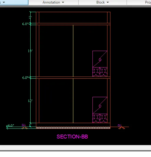
2.SECTION-BB:
* Using the commands line,Polyline, offset,fillet,trim,and hatch created the sectional view for the section-BB.
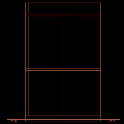
* Dimensions are given using the DIM-LIN command.
* Using Dtext command, the name is given in the bottom.
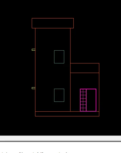
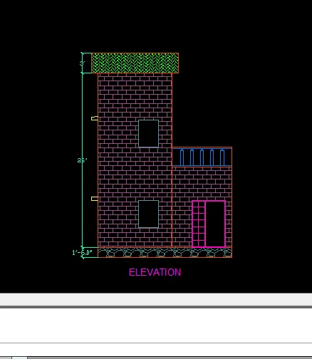
3.ELEVATION;
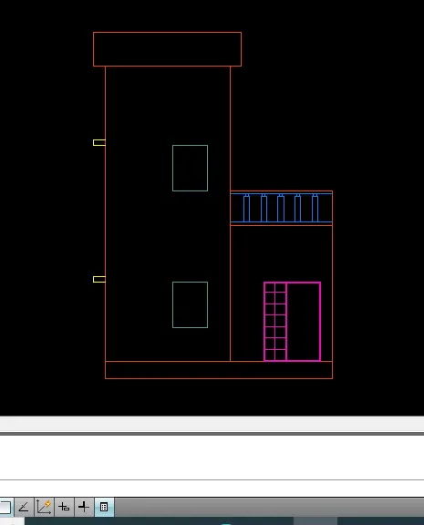
* Using the commands line,Polyline, offset,fillet, trim and hatch, i have created the sectional view for the elevation.

* Provided windows as per the plan, and door as per plan.
* Provided lintel beam over the windows,doors.
* Provided parapet wall.
* Provided balcony.
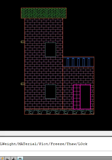
* Using Hatch command, i have filled super structure below parapet wall with BRICK and adjustment the scale for better visibility.
* Using hatch command, i have filled parapet wall with SOLID and adjusted and scale for better visibility.
* Using the command DIM-LIN, i have provided dimensions whenever required.
* And using Dtext command, the name is given in the bottom and staircase dimensions are mentioned.
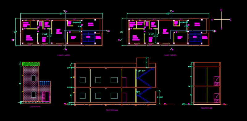
* The following image shows the ground floor first floor plan, front elevation and section A & B, together.
II. STRUCTURAL DRAWINGS;
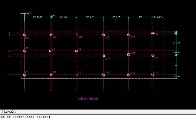
1.Column layout;
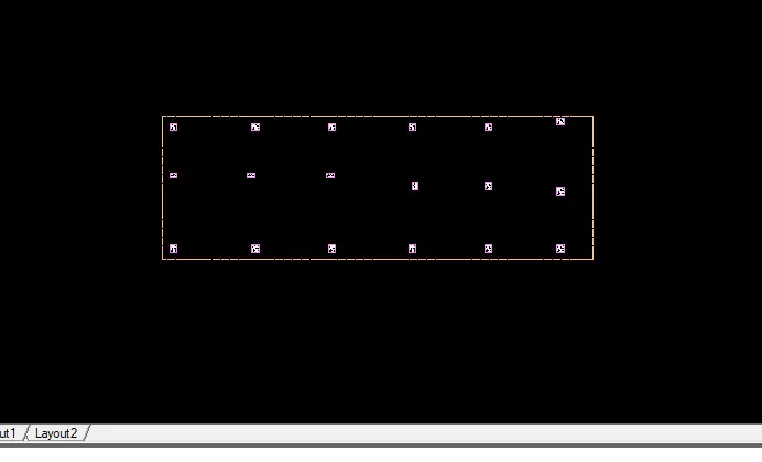
* Turn off all the layers except the column layer and boundary layer in the layer properties.
* Select the copy tool by typing CO or COPY in the command box.
* Select all the culumns from the building plan and copy them to deffernt location as shown in figure below.
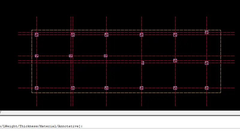
* Select the cinstruction line tool by typing XL or XLine in the command box.
* Select the line type as ISO 02W1000` and give scale as per requirement.
* Draw lines through the midpoint of the column in horizontal and vertical direction as shown in the figure below.
* Select the trim tool by typing TR or TRIM in the command box.
* Trim the unnecessary lines and press esc to cancel th trim command.
* Select the dimension tool by typing DIM in the command box.
* select the first point and the second point of the object to measure. repeat for all the object to be measured.
* Enter DS in the command box to open the dimension style manager dialog.
* Modify the dimensions as per the requrement.
* Change the color of the dimension and extension line as per the requirement.
* Under the text option, Change the text height to 8"
* Click ok, then clickset current and close the dimension style manager dialog box.
* Give dimensions and text as per the drawing and requirement using the Mtext command and dimension command.
2.Beam layout;
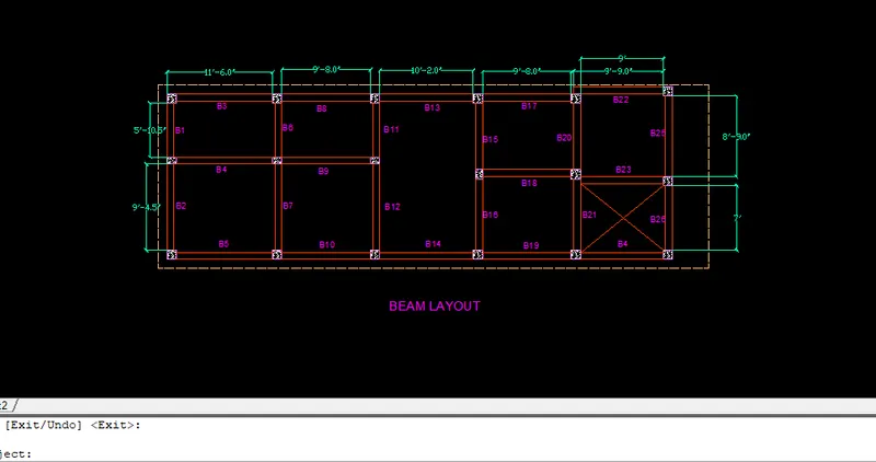
* Turn off all the layers except the column layer and boundary layer in the layer properties.
* Select the copy tool by and typing in command box.
* Select all the column from the building plan location as shown in figure below.
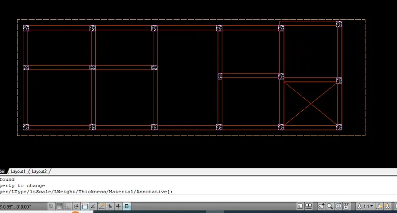
* Select the construction line tool by typing XL or XLIne in the command box.
* Select the line type as ISO 02W100 and give scale as per requirement.
* Draw lines through the midpoint if the columns in horizontal and vertical direction as shown in the figure below.
* Select the trim tool by typing TR or TRIM in the command box.
* Trim the unnecessary lines and press Esc to cancel the trim command.
* Speccify offset distance as 4.5' and create offset for the beam of width 9" and them press Esc.
* Select the offset tool again by typing O or offset in the command box.
* Specify offset distance as 3" and create offset for the beam of width 6" and then press Esc.
* Select the trim tool by typing TR or Trim in the command box.
* Trim the unnecessary lines and press Esc to cancel the command
* Assign the beamlines to the beam layer.
* Select the dimension tool by typing DIM in the command box.
* Select the first point and the second point of the object to be measured . Repeat for all the object to be measured.
* Enter DS in the command box to open the dimension style manager dialog.
* Modify the dimension as per the requirement.
* Change the color of the dimension and extension line as per the reequirment.
* Under the text option, change the text height to 8".
* Click ok , then click set current and close the dimension style manager dialog box.
* Give dimensions and text as per the drawing and requirement using the Mtext command and dimension command.
3. FOOTING LAYPOUT
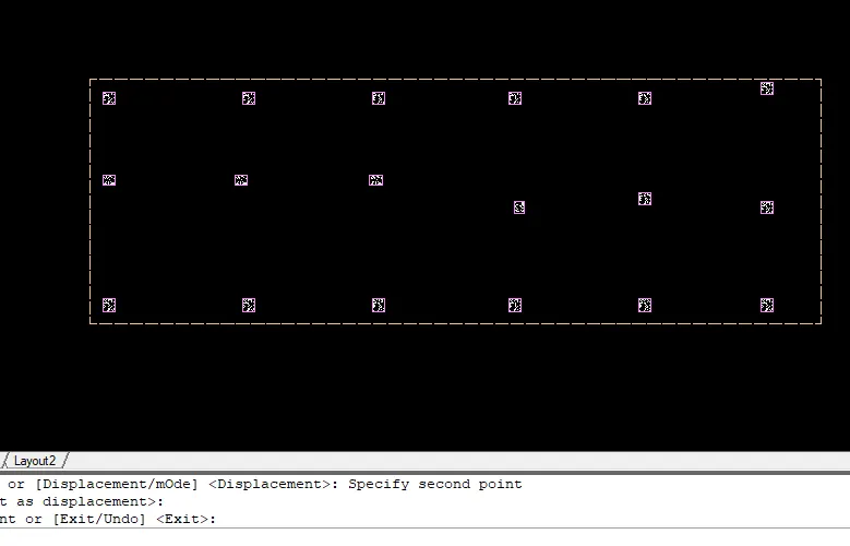
* Turn off all the layers except the column layers and boundary layers in the layers properties.
* Select the copy tool by typing co or copy in the command box.
* Select all the column from the building plan and copy them to a different location as shown in the figure below.
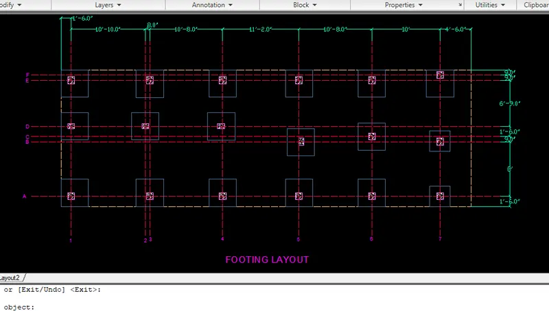
* Using the line command , the square footing of size 4'*4' is provided for all the columns except for staircase column.
* Using the CENTERLINE line type, the grid lines are provided.
* Using the DIM-LIN and DIM- CONTINUE command, the dimension between the grid lines are mentioned.
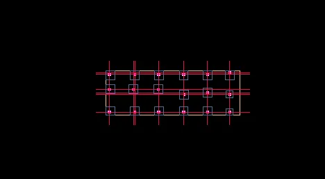
* Also using the DIM-LIN command , the column position in footing is mentioned.
* Using Dtext command , the grid names and titel is given.
* For better visibility, i have provided colors for grid lines and dimensions between grid lines.
* Select the trim tool by typing TR or trim in command box .
* Trim the unnecessary lines and press Esc to cancel the command
* Select the dimension tool by typing DIM in the command box .
* Select the first point and the second point of the object to be measured . repeat for all the object to be measured.
* Enter Ds in the command box to open the dimension style manager dialog.
* Modify the dimensions as per the requirment.
* Change the color of the dimension and extension line as per the requirement.
* Using the text option , change the text height to 8".
* Click ok , then click set current and close the dimension style manager dialog box.
* Give dimensions and text as per the drawing and requirement using the mtext command and dimension command.
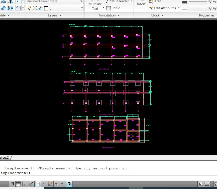
* The following image shows the column layout ,footing layout, and beam layout together.
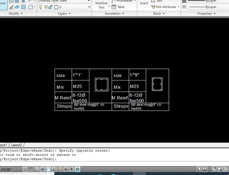
* Using the commands linje, offset,circle, hatch and dtext the
1-Column schedule
2- Footing size.
Footing size;
* footing size is 4'*4'.
Result;
Both Architectural and structural drawing are shown below again.