Project 1 _Creating an Architectural plan for the provided plot size and develop relevant basic structural drawings
Q-Design and Draft a layout of a residential building with the following details:
a. Plot Size: 60’x20’(18.3m x6m)
b. Orientation- Facing East
c. Develop the following: 1. Architectural Drawing (Floor Plan, Elevations, and Sections) 2. Structural Drawing (Column, Bean, Footing Plan)
AIM AND INTRODUCTION : Layout plan of a residential building is required to be drafted and designed. Also Architectural Drawing ( Floor Pkan, Elevations, and sections) also to be developed. Structural Drawing of Column, Beam and Footinf need to be developed.
NOTE : AS THE PLOT SIZE WAS NOT FITTING ON THE SCREEN WITH THE PROPER SIZE , SOME SNAPS HAVE BEEN TAKEN TWICE- ONE WITH LARGER IMAGE OF PARTICULAR WORK AND OTHER WITH FULL PLOT SIZE.
PROCEDURE IN DETAIL :
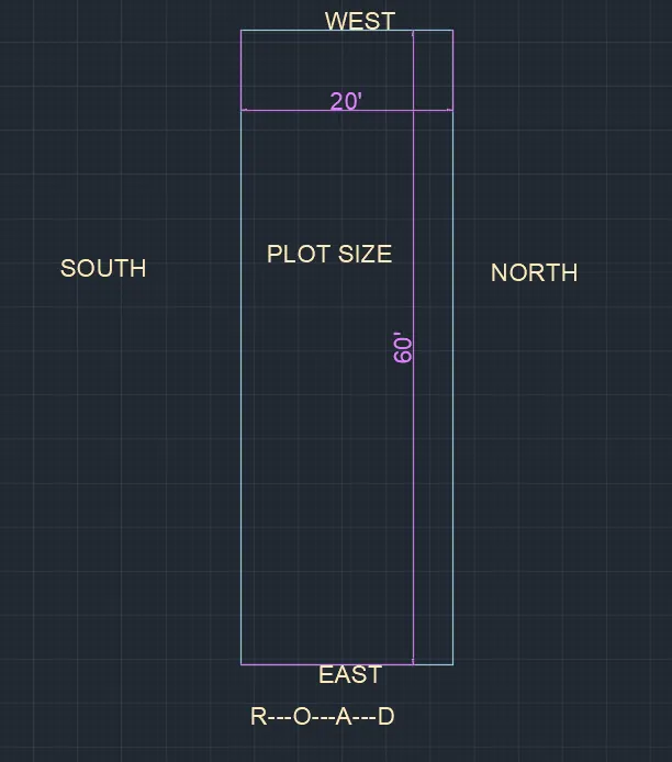
PLOT SIZE : 20'X 60' EAST FACING
SNAP SHOT-1 : Commentary-
- Boundary of Plot of size 30" x60' is drawn using XL ( H/V) command.
- MT command is used to indicate text ( directions).
- DIMA Cmmand is used to indicate dimenstin of plot.
- TRIM Command is used to trim unwanted lines
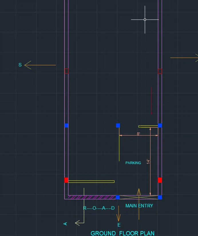
SNAP SHOT-2 : Commentary-
- The plot is East facing as shown ( Main road is infront of house on East direction.
- Right infront of road in the begining of plot space for car parking and front lawn has been planned using offset and trim command
- External walls have been assumed 9" thick.
- Internal wall thickness has been assumed as 4.5' thick.
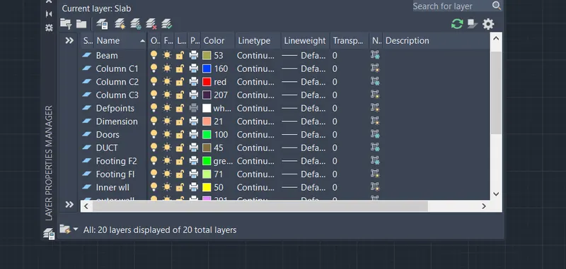
- Plan is created using layer command having different properties of layer . Important components of construction are created in different layer.
SNAP SHOT- 2' : Commentary- Layers has been created for different components of Building. Simmiler types of components have been kept in the same layers for better control and Editting.
SNAP SHOT- 3: Commentary-
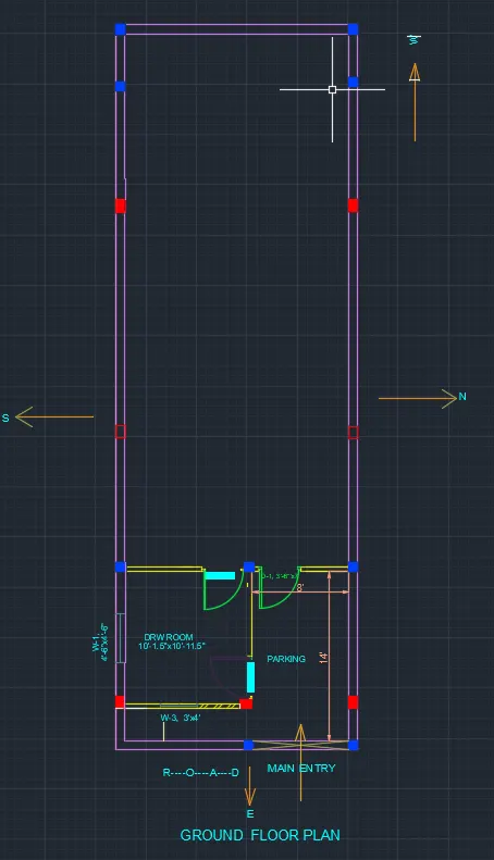
Drawing room of size as mentioned in the lay out ( snap shot), doors and windows are i created using following command-
- Offset command
- Arc command
- Line command
- Trim command
- Mirror command
- Rotate command
- Copy command
- Paste command
- DIMA Command
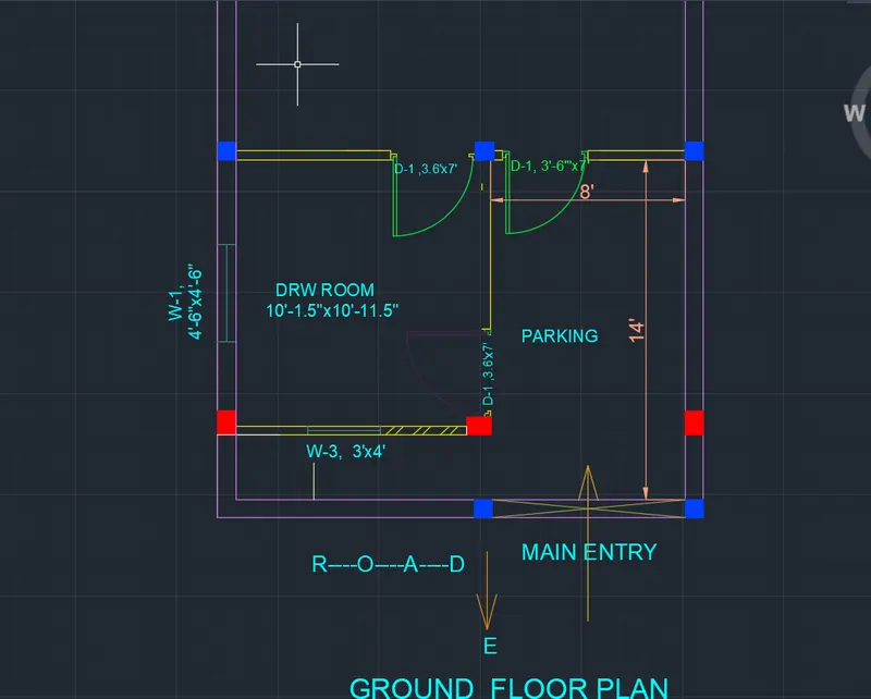
Full Snap shot of above part plan-
SNAP SHOT-4 & 4': Commentary-
Kitchen room of size as mentioned in the lay out ( snap shot), doors and windows are created using following command-
- Offset command
- Arc command
- Line command
- Trim command
- Mirror command
- Rotate command
- Copy command
- Paste command
- DIMA Command
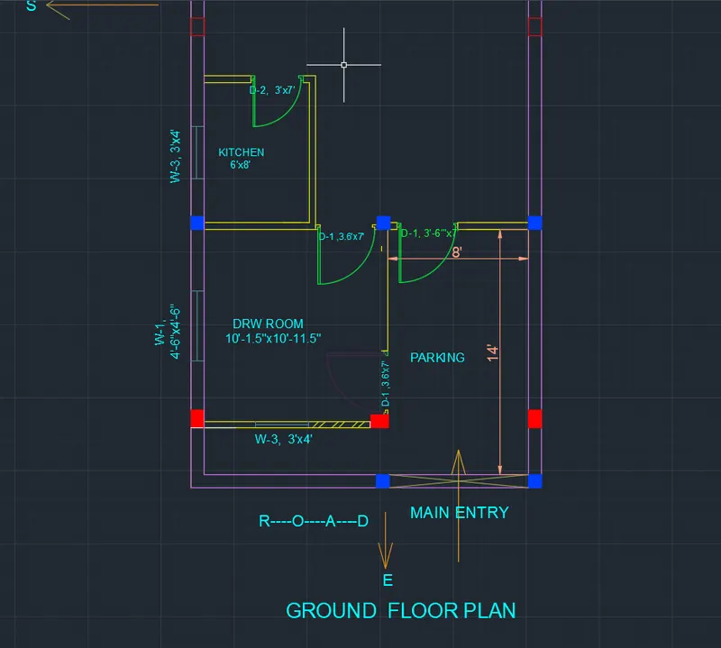
Full Snap shot of above part plan showing Kitchen in addition to other parts of home plan-
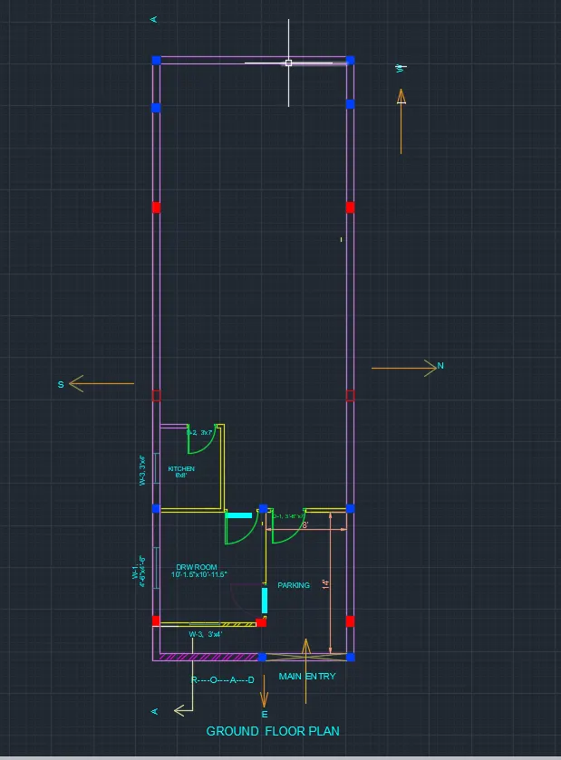
SNAP SHOT- 5 & 5': Commentary-
Stair case as mentioned in the lay out ( snap shot), is created as per the dimension and calculation given below using commands as mentioned above-
Design of stair case :
Floor Height : 9' 6"
Riser : 9"
Tread : 11"
No. of Risers : 9' 6"/9" = 14
No. of Riser in each flight : 7
No. of Treads : Riser -1 = 7-1 = 6
Length required for Tread : 6x 11" =66" = 5' 6"
Width of Landing : 3' ( Assumed)
Total length for stair case : 5' 6" + 3' = 8' 6"
Width of each step : 3'
Min width of stair case : 2x 3' = 6 '
Thus space of 8' 6" x 6' is reqired for setting up stair case.
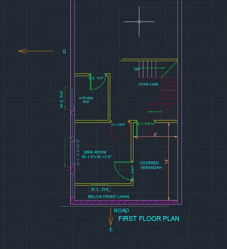
Full Snap shot of above part plan showing Stare case in addition to other parts of home plan-
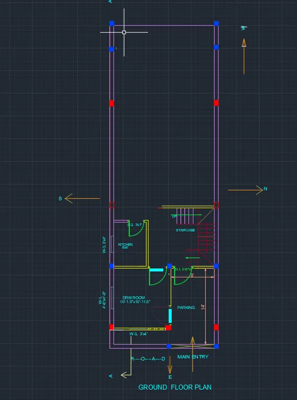
SNAP SHOT 6 & 6'- : Commentary-
- Bed room as mentioned in the lay out ( snap shot), is created as per the dimension a using commands as mentioned above
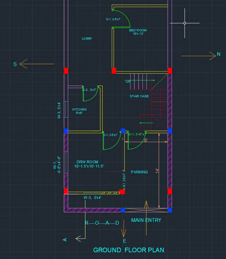
Full Snap shot of above part plan showing Bed room in addition to other parts of home plan-
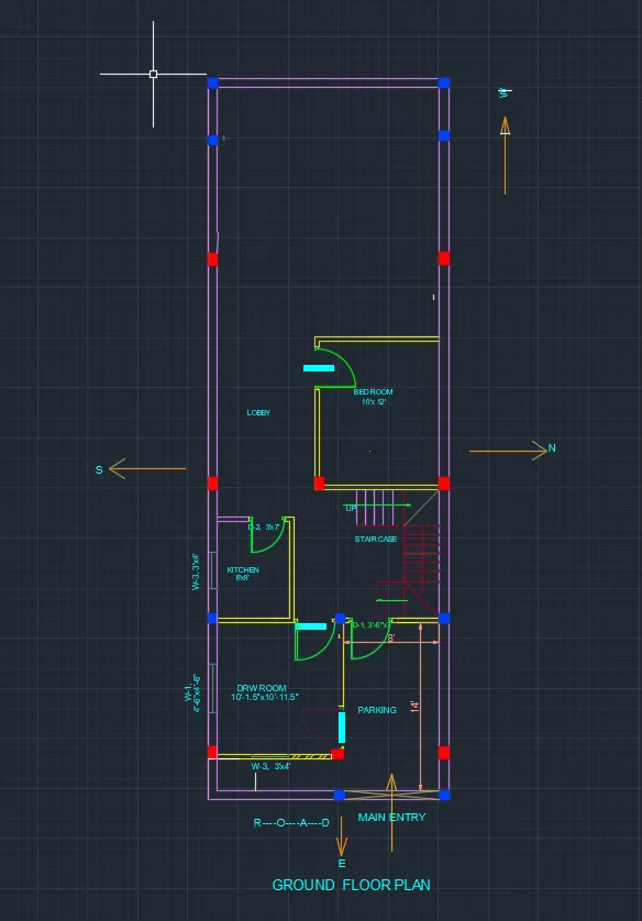
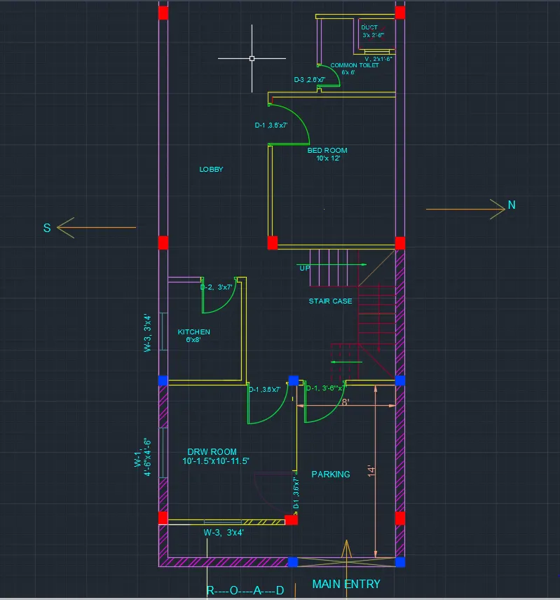
SNAP SHOT- 7 & 7' : Commentary-
- Common Toilet of size 6'x6' adjacent to the Bed room is also created.
- Open duct of measure 3'x2'-6" in the toilet area is also planned for Ventilation.
- Hatch command is used to hatching as per requirement.
SNAP SHOT - 8 & 8'
: Commentary-
-
- Two Bed rooms as mentioned in the lay out ( snap shot), is created as per the dimension indicated a using commands as mentioned above .
- Common Toilet of size 6'x6' adjacent to the Bed room is also created.
- Open duct of measure 3'x2'-6" in the toilet area is also planned for Ventilation. Utility area can be utilised for washing cloths and keeping househols which are not used daily.
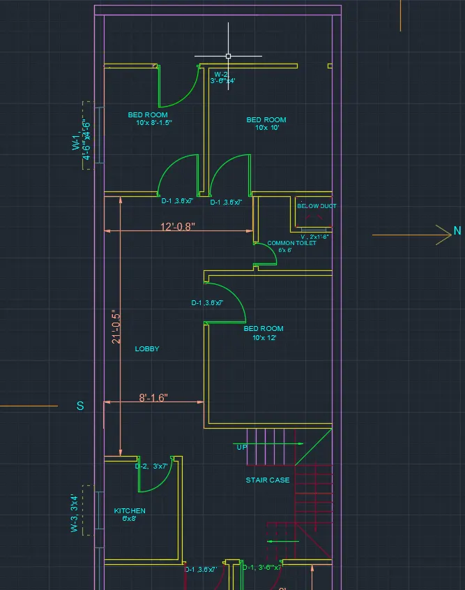
Plan on full plot size-
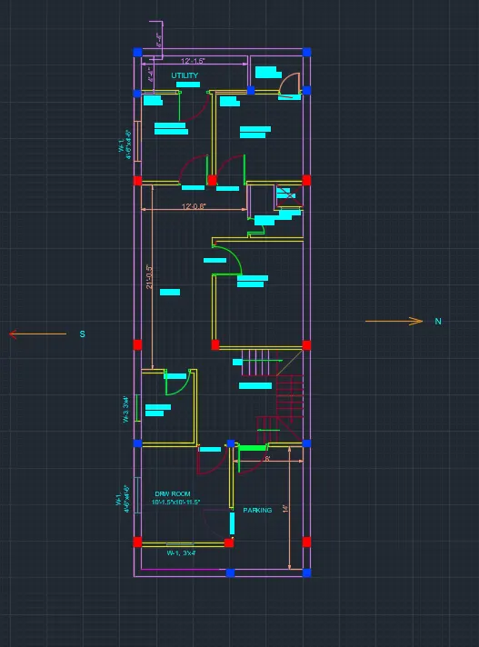
SNAP SHOT- 9 : Commentary-
- On the Rear side of two Bed rooms one attached Toilet and utility area, Windows are provided for ventilation and sunlight.
- Common Toilet of size 6'x6' adjacent to the Bed room is also created.
- Open duct in utility area area is also planned for Ventilation. Utility area can be utilised for washing cloths and keeping househols which are not used daily.
- A big Lobby is also planned which can be utilizes for Dining purpose.
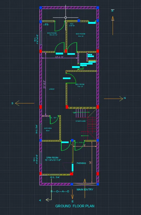
SNAP SHOT- 10 : Commentary-
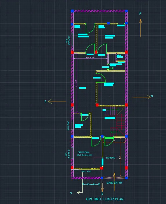
Ground Floor Plan is drawn using command as specified above.
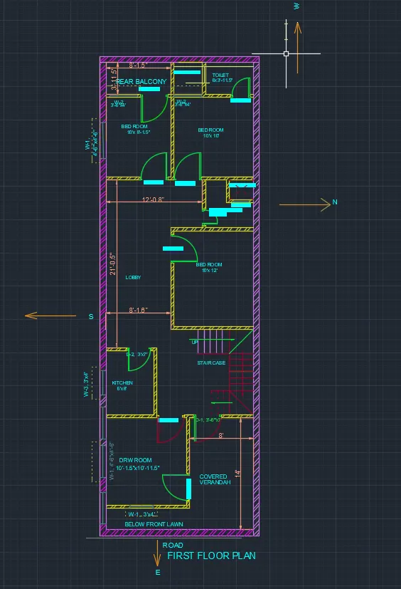
SNAP SHOT- 11 : Commentary-
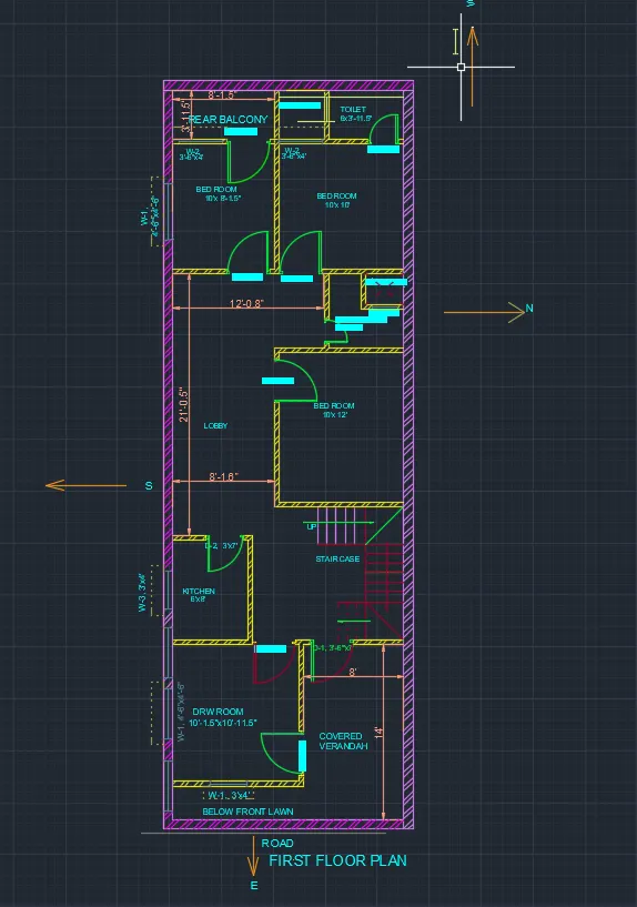
First Floor Plan is drawn using command as specified above.
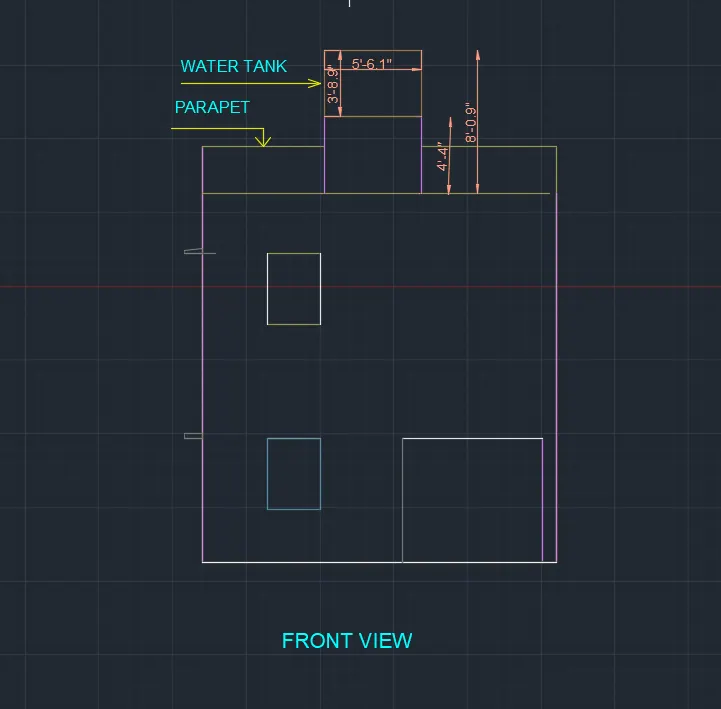
SNAP SHOT- 12 : Commentary-
Front Elevation has been drawn as below-
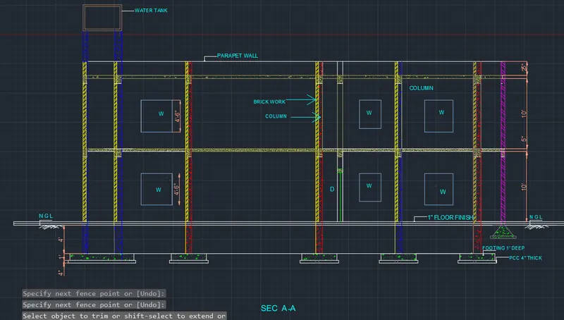
SNAP SHOT-13 : Commentary-
Section through A-A is drawn as shown below-
SNAP SHOT- 14 : Commentary-
Structural plan at ground level consisting oF Beams Columns anf Footings arrangement . Footing detail has been indicated here.

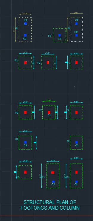
SNAP SHOT- : Commentary-
Structural plan of Columns anf Footings
SNAP SHOT- 15 : Commentary-
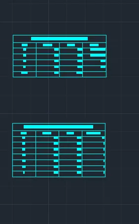
Schedule of Door, Window, Ventilator, Column, Footing and Beam.
RESULT :
Thus 1) Design and Draft a Layout of a residential building with the given details has been designed and drafted:
2) . Architectural Drawing (Floor Plan, Elevations, and Sections), Structural Drawing (Column, Bean, Footing Plan) has also been developed
-------------------------xxxxxxxxxxxxx------------- END OF PROJECT ------------xxxxxxxxxxxxxx---------------------------------