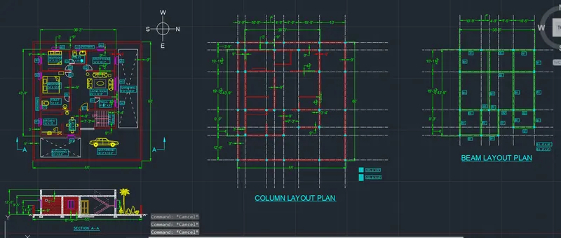
Project 1 _Creating an Architectural plan for the provided plot size and develop relevant basic structural drawings
AIM
⦁ To create a architectural plan for provided plot size and develop relevant structural drawings.
COMMANDS USED:
⦁ Line
⦁ rectangle
⦁ trim
⦁ fillet
⦁ offset
⦁ design centre
⦁ dimlinear
⦁ dimstyle
⦁ mleader
⦁ mtext
⦁ circle etc.
PROCEDURE:
STEP 1:
CREATE A ARCHITECTURAL PLAN:
⦁ Set the units in architectural feet and inches and limits min and max.
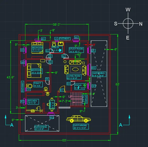
⦁ draw a layout of a building plot size of 55' x 60' using a rectangle command.
⦁ offset 9" to create a compound wall.
⦁ draw a rec for 38'-3" and 43'-9" to create a builtup area.
⦁ offset it to 9" to create a outer wall.
⦁ offset the dimensions to create a plan of the building .
⦁ use 4.5" for the inner wall thickness.
⦁ create the stair case for 10'x8' and provide a treat 10" and riser 7".
⦁ use the dim linear command to provide the dimension.
⦁ use the mtext command to provide the text .
⦁ name the every room with the inner dimensions.
⦁ use the design centre command to create architectural materials like cars kitchen utilities bed room utilities.
⦁ create the door 1 - 4'x7'
⦁ door 2 -3'x7'
⦁ door3 -2'-6"x7'
⦁ create the windows
⦁ W1 - 3'x4'
⦁ W2 - 6'x4'
⦁ W3 - 2'x2'
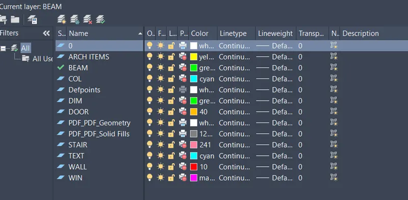
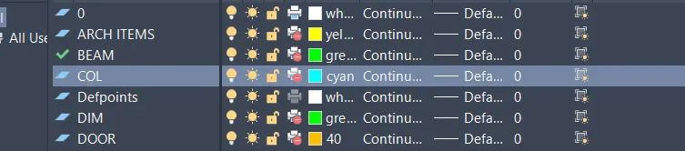
⦁ by using the layer command separate the wall, dim, text, architectural aminities, stair to a different layer and give a different colour.
⦁ the architectural plan of a building is drawn using the autocad.
STEP 2:
CREATE A ELEVATION VIEW:
⦁ Use the xline command to create the vertical lines to trace the column and window locations to draw a section view.
⦁ offset the 7' from the ffl level to creaate a door and window.
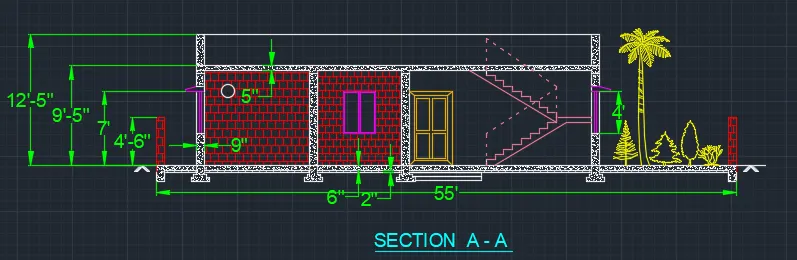
⦁ offset the 9'-5" to create the top level and 9' to create the bottom of slab level.
⦁ offset the 3' dim to create the parapet wall.
⦁ draw the stairs using the tread and riser value.
⦁ use the dim linear command to provide the dimension.
⦁ use the mtext command to provide the text .
⦁ split them into each layer by using the layer command.
⦁ use the design centre command to create architectural materials like cars kitchen utilities bed room utilities.
⦁ the section view of the building plan is drawn.
STEP 3:
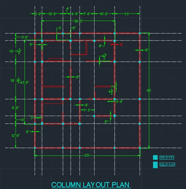
CREATE A COLUMN LAYOUT PLAN (STRUC. DRAWING):
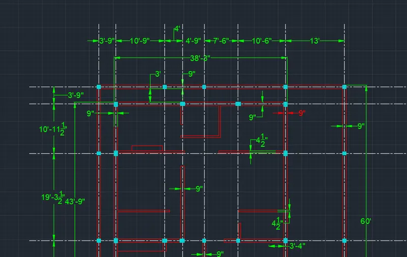
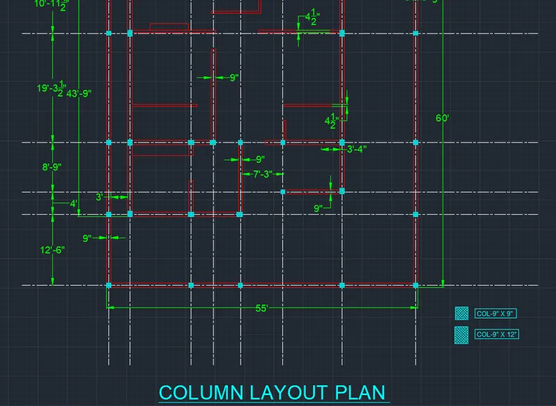
⦁ Draw a center line by using the command line and change the line type to centered and change the linetype scale.
⦁ turn on the layer of wall and other remaining layers are in offmode.
⦁ mark the columns .
⦁ C1 - 9"X12"
⦁ C2 - 9"X9"
⦁ Give the hatch to the column by using hatch command.
⦁ mark the dimensions of column location and text the name.
⦁ separate the layers of column by using the layer command.
⦁ the column layout plan is drawn by using the autocad.
STEP 4:
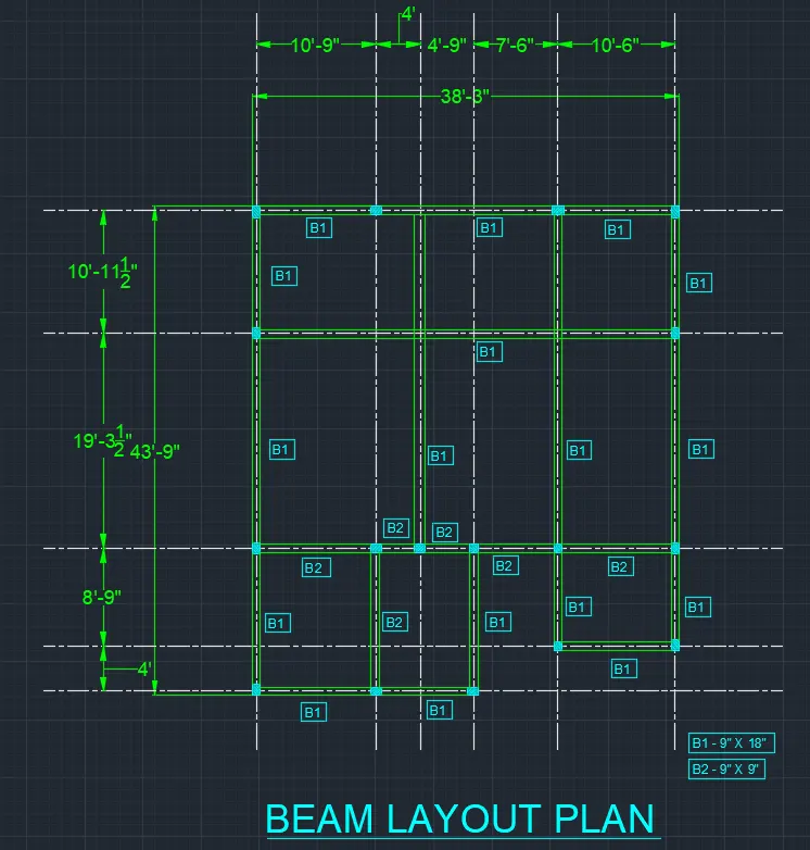
CREATE A BEAM PLAN:
⦁ Copy the column plan of the buiding and paste it.
⦁ turn on the column layer.
⦁ draw a beam from column to column.
⦁ draw a B1 beam for the outer wall locations and the longer span areas.
⦁ mark it in the plan by using the mtext command.
⦁ mark the dimensions.
⦁ create the layer name beam and give the separate colour.
⦁ change the layer property of the line to beam.
⦁ draw a B2 beam for the inner wall locations.
⦁ B1 - 9"X18"
⦁ B2 - 9"X9".
⦁ the beam plan of the residential building is drawn using the autocad.
RESULT:
⦁ The architectural plan for provided plot size and the section, column plan and beam plan (struc. drawings) are drawn using the autocad.