Creating Bar Bending schedule, Different Door types, and Creation of standard drawing templates using AutoCad
AIM:
⦁ To create a template, inserting texts and attributes by using the autocad.
COMMANDS USED:
⦁ Block
⦁ insert
⦁ attributes
⦁ field
⦁ rectangle
⦁ line
⦁ text
⦁ mirror
⦁ copy
⦁ offset
PROCEDURE:
CUSTOM TITLE BLOCK1:
⦁ Set the units and limits command.
⦁ create a rectangle of size and divide it with the line for the text box into columns.
⦁ For the rows, take offset the line for the required dimensions in mm.
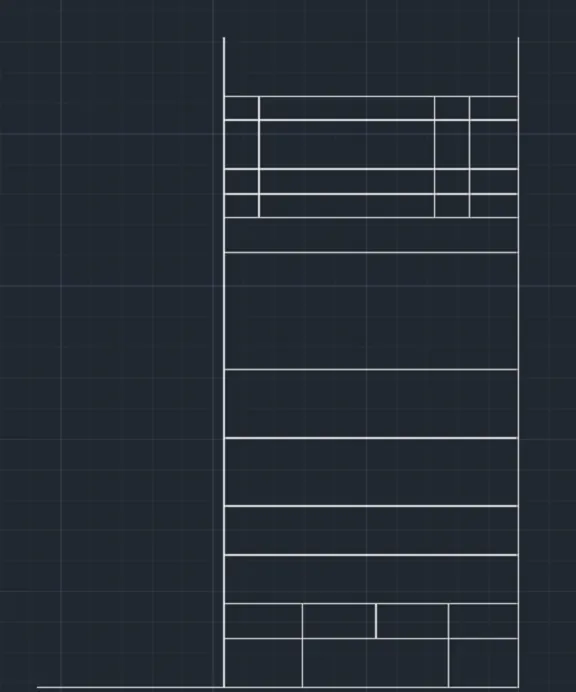
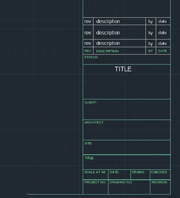
⦁ By using the multiline text command type the texts.
⦁ again use the same command and type the text in caps with different height.
Creating block:
⦁ command B - block definition dialogue box.
⦁ give the name custom1_title block.
⦁ select pick point and select the point in a table.
⦁ select the object and tick the exploding.
⦁ select the convert to block option.
⦁ as we have retained the object it will be retain and same as the actual drawing and a block is created for the objects.
CUSTOM 2 TITLE BLOCK:
⦁ Draw a rectangle at the right corner and explode it.
⦁ split the lines as required rows and columns.
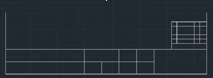
⦁ use the multiline text type the texts.
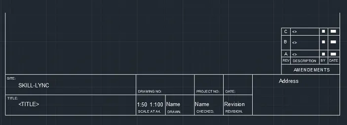
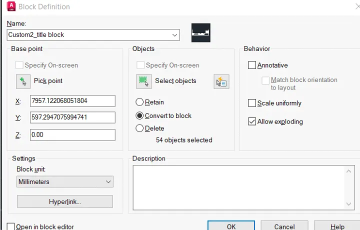
⦁ create a block using the command B in the name of custom2 title block.
⦁ select the pick point and the whole object to create a block.
RESULT:
⦁ The templates are drawn and created as block using the autocad.
AIM:
⦁ To create the different types of doors for the warehouse and placing it in blocks.
PROCEDURE:
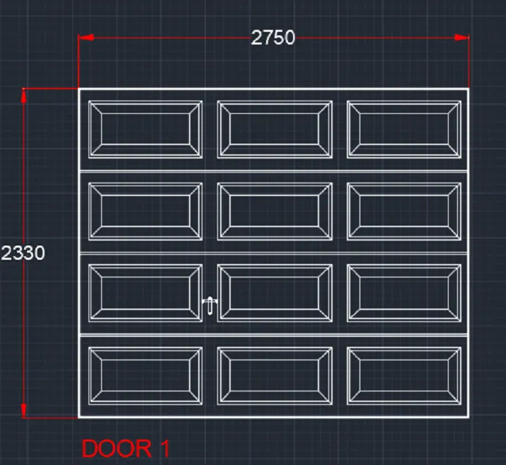
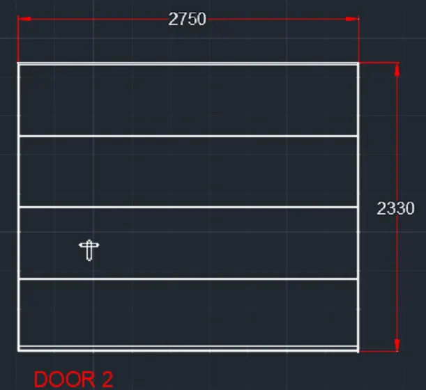
⦁ Create a rectangle of size 2330X2750mm.
⦁ offset 50mm as a frame. 90mm for the top left side and explode the rectangle..
⦁ divide the lines into the segments horizontally and vertically.
⦁ offset the 25mm on both sides and delete the centre line.
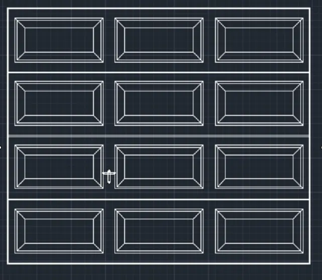
⦁ create a rectangle to show the panels. offset the 20mm from the 1st rectangle and offset 100mm from the 2nd rectangle.
⦁ draw lines joining the corners of the outside and inside of rectangle.
⦁ create the panel as a block and so it is east to copy.
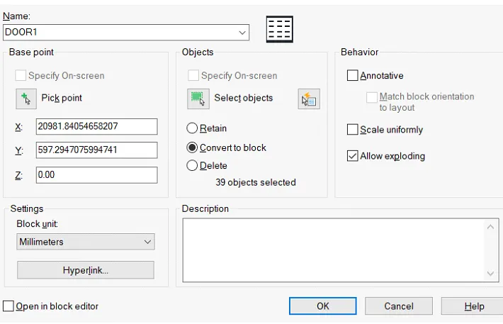
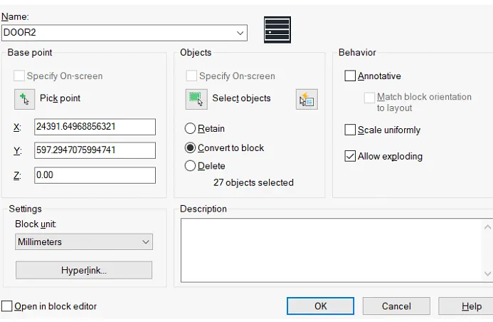
⦁ use the command B and create the block. give the name as door 1 and pick the point and select the corner point .
⦁ select the object and create a block.
⦁ create a rectangle of size 2330x2750mm.
⦁ copy the door frame of door 1.
⦁ offset the 25mm on both sides for the thickness, delete the centre line .
⦁ create the block using the command B .
⦁ Pick a corner point and select the whole door.
⦁ name it as Door 2.
RESULT:
⦁ The doors for the warehouse are drawn and created as block by using the autocad.
AIM:
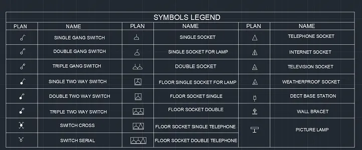
⦁ To create the electrical legend and create the each symbol after that create them as block and aranging them in legends.
PROCEDURE:
⦁ Create the electrical symbols.
⦁ single gang switch: draw a circle of radius with line draw an inclined line vertical and horizontal line perpendicular to the inclines as required.

⦁ triple gang switch.
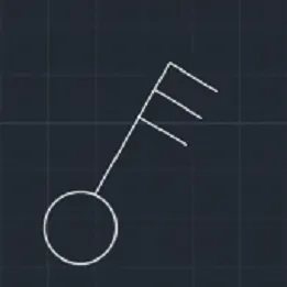
⦁ single twoway switch.

double twoway switch.

triple twoway switch.

switch cross

switch serial

single socket
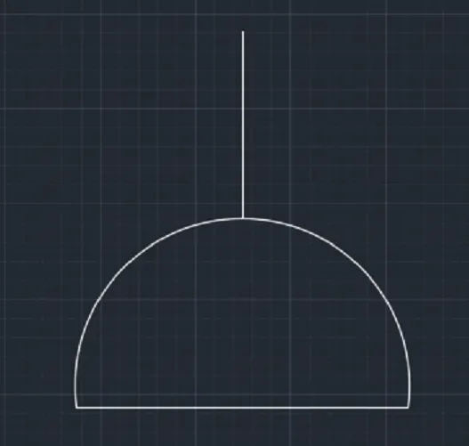
single socket for lamp
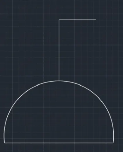
double socket
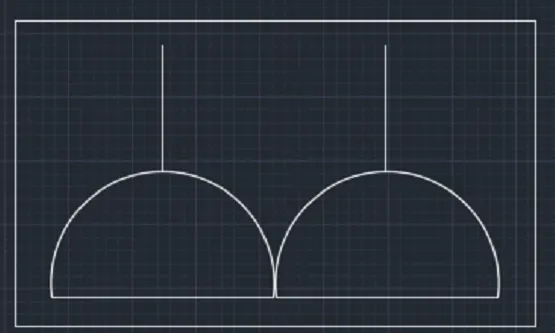
floor socket single
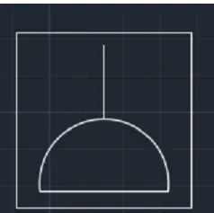
floor single socket for lamp
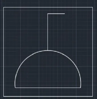
floor socket doubler
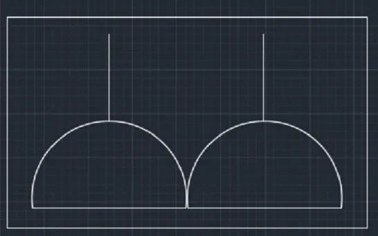
floor socket single telephone
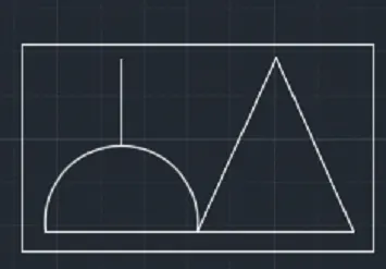
floor socket doubke telephone
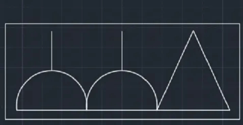
telephone socket
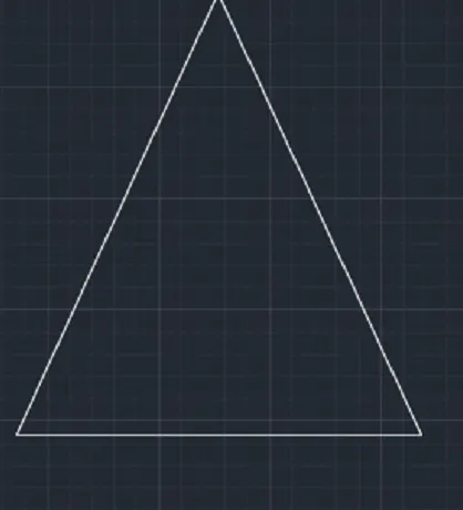
internet socket

tv socket

weather proof socket
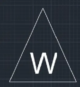
duct base section
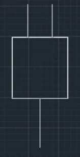
wall bracket
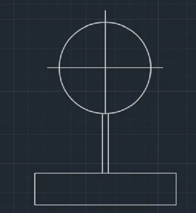
picture lamp
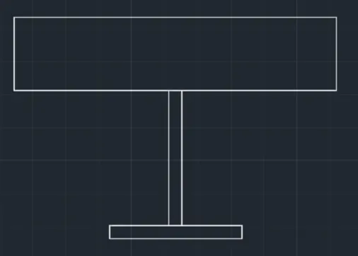
⦁ create them each as a block by using the command B and pick a point and select the object.
⦁ create a table by using the line command and name the texts.
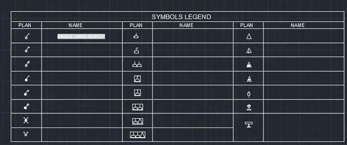
⦁ place the electrical symbols and use the command field and place the name of every electrical legend blocks.
⦁ after placing of the names explode the names.
RESULT:
⦁ The electrical symbols are drawn and created and tabulated by usign the autocad.
AIM:
⦁ To create a door type for the residential building as a block.
PROCEDURE:
⦁ In the command prompt type units as engineering inches.
⦁ set the limits.
⦁ type zoom enter and all enter.
⦁ type the line command and draw the door with the given measurement.
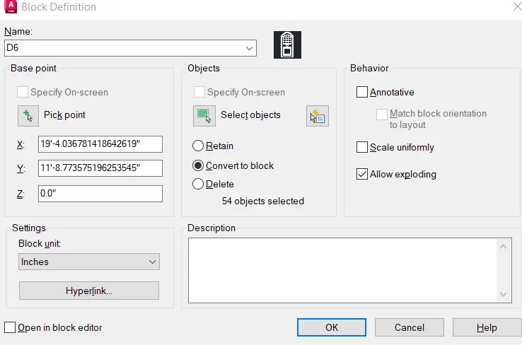
⦁ create a block by using the command B and name the door and pick the point and select the object.
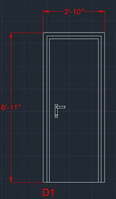
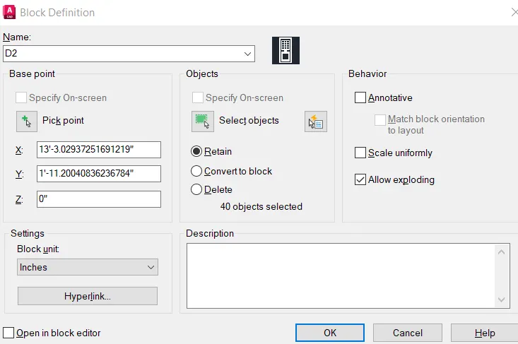
⦁ use the same command and draw the door 2.
⦁ create a block by using the command B and name the door and pick the point and select the object.
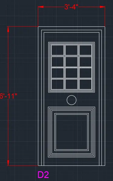
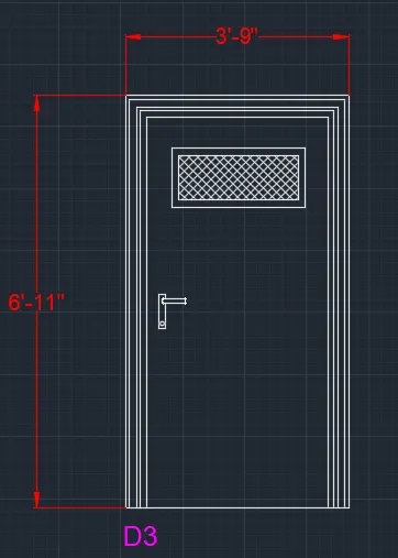
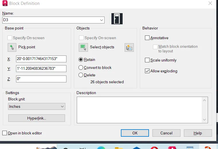
⦁ use the same commands and draw the door 3.
⦁ create a block by using the command B and name the door and pick the point and select the object.
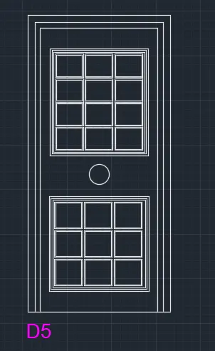
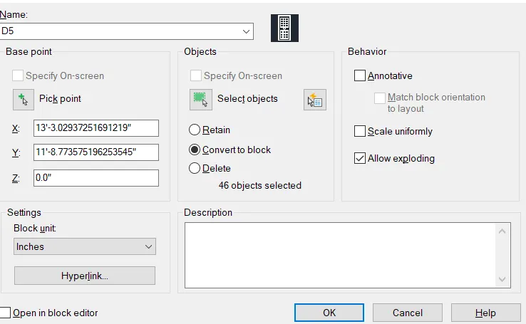
⦁ use the same commands and draw the door 5.
⦁ split the panels in the door.
⦁ create a block by using the command B and name the door and pick the point and select the object.
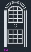
⦁ use the same command and draw the door 4.
⦁ fillet the radius of each line to get the arch door
⦁ create a block by using the command B and name the door and pick the point and select the object.
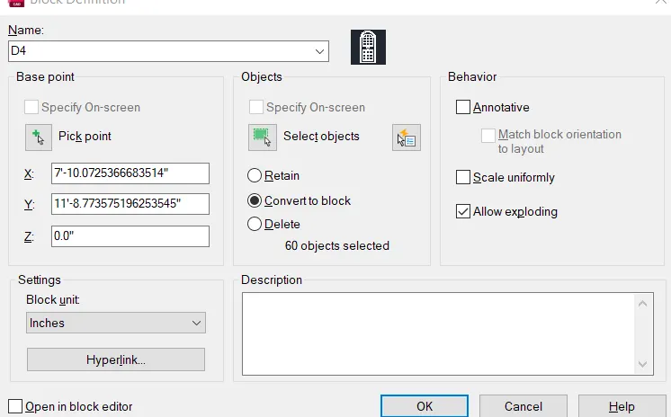
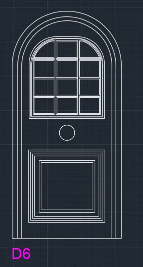
⦁ use the same command and draw the door 4.
⦁ fillet the radius of each line to get the arch door
⦁ create a block by using the command B and name the door and pick the point and select the object.
RESULT:
⦁ The doors for the residential buildings are drawn and created as blocks by using autocad.
AIM:
⦁ To create the each shape a block and insert it on the table.
PROCEDURE:
⦁ Set the units and limits.
⦁ draw the shapes by using the line command and fillet them with the required radius.
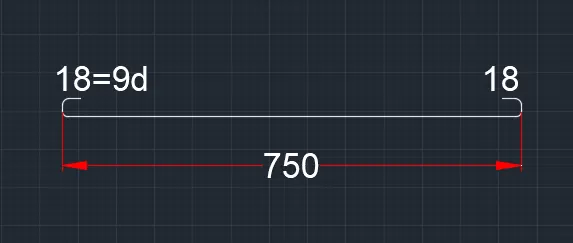
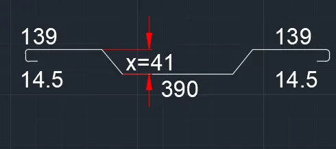
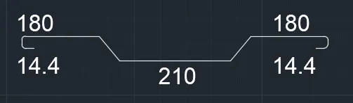
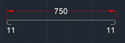
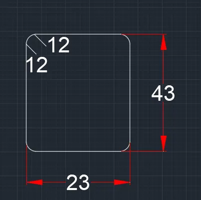
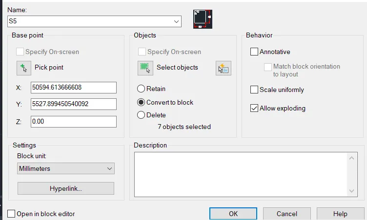
⦁ create a block by using the command B and name the shapes and pick the point and select the object.
⦁ repeat the procedure for all the shapes.
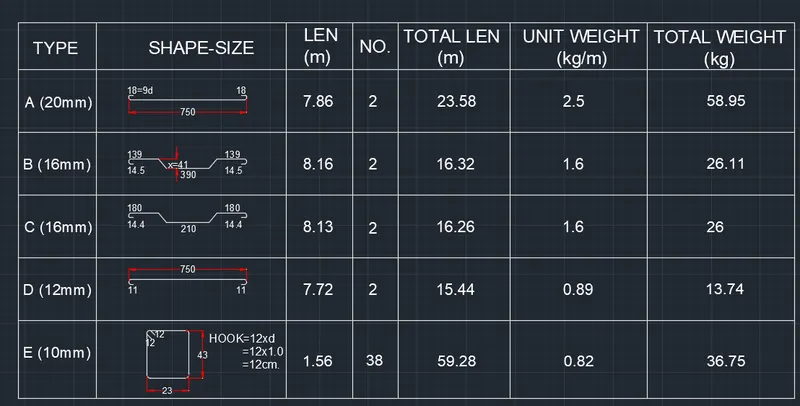
⦁ create the table with the rows and columns.
⦁ type the headers using multiline text command.
⦁ insert the shapes which is created as a blocks.
⦁ enter the values in the table by using the multiline text command.
RESULT:
⦁ The shapes are created as a block and inserted it on the table by using the autocad.