Creating Kitchen layout, Hatching of Architectural elements and sectional view of an Industrial Building in AutoCad
1. AIM:
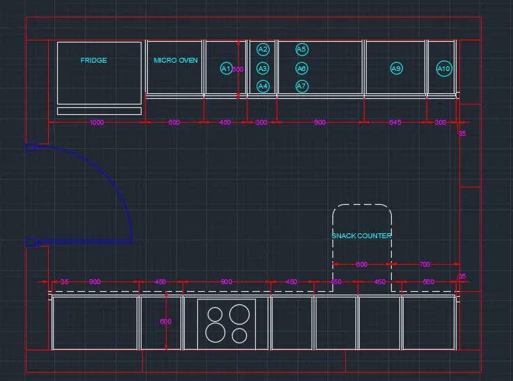
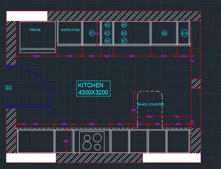
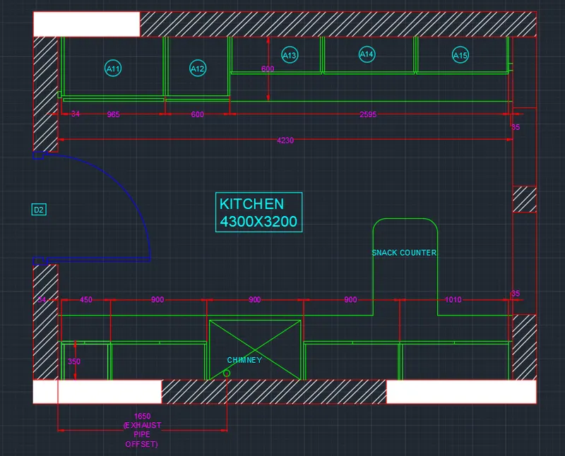
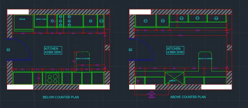
⦁ To create the kitchen layout and also use the proper dimension techniques to dimension the kitchen layout. use the hatch properties wherever required.
PROCEDURE:
⦁ Set the units to mm
⦁ set the limits min and max.
⦁ enter the comman zoom and all.
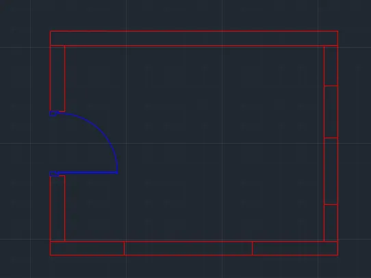
⦁ Type the rectangle and the dimensions are 4734x3688mm.
⦁ offset the distance of 230mm for wall
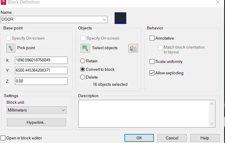
⦁ use the arc and lines draw the door and create it as a block by using block properties.
+
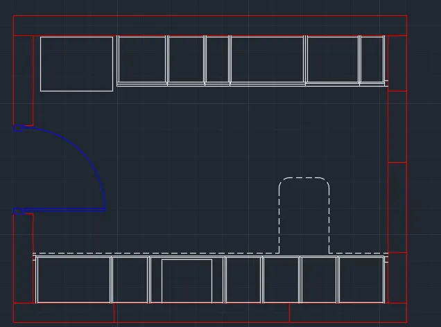
⦁ Use the line command to daw the kitchen utilites .
⦁ use the commmand design centre to get the kitchen utilities.
⦁ offset the lines in horizontal distance 350,450,900,450,450 & 560.
⦁ in the command prompt, type the line and load the dotted lines
⦁ in the command prompt, type the text to text annotations.
⦁ use the command dimlin to create the dimensions.
⦁ use the hatch properties and hatch the wall.
RESULT:
⦁ The kitchen layout and hatching properties are done by using the autocad.
2. AIM:
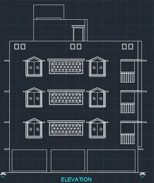
⦁ To create the elevation of the plan with hatch.
PROCEDURE:
⦁ In the command prompt type the line command to draw the lines.
⦁ use the rec command and use the proper dimensions to draw the outer wall in elevations.
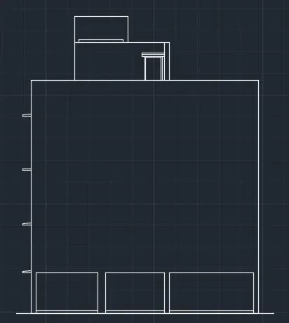
⦁ use the command line rec and arc draw the window.
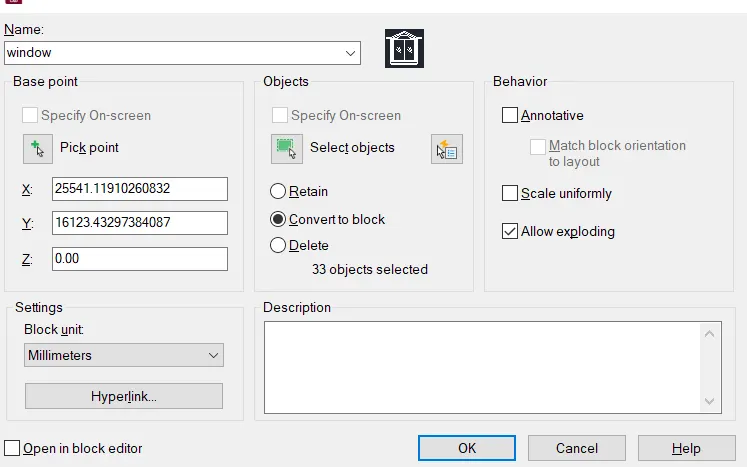
⦁ use the block command and create it as the block and insert it multipples.
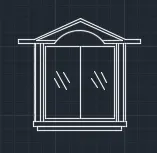
⦁ repeat the commands and create the windows.
⦁ after creating the window and create it as the block to use it continuously.
⦁ use the hatch properties to fill the portions to differentiate.
⦁ use the mtext command to create the texts.
RESULT:
⦁ The elevation of the plan is drawn by using the autocad.
3. AIM:
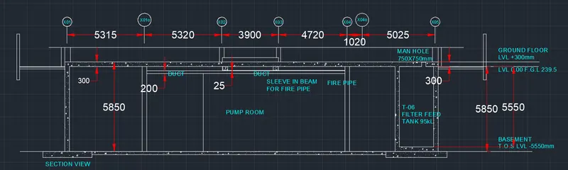
⦁ To create the section view of the industrial building.
PROCEDURE:
⦁ Use the command l and draw the lines use the proper dimension.
⦁ use the offset command and offset the line to create the grid.
⦁ use the command text to name the grids.
⦁ use the circle command to frame the grid names.
⦁ draw a concrete wall with the proper dimension as shown.
⦁ use the hatch properties to hatch the concrete wall.
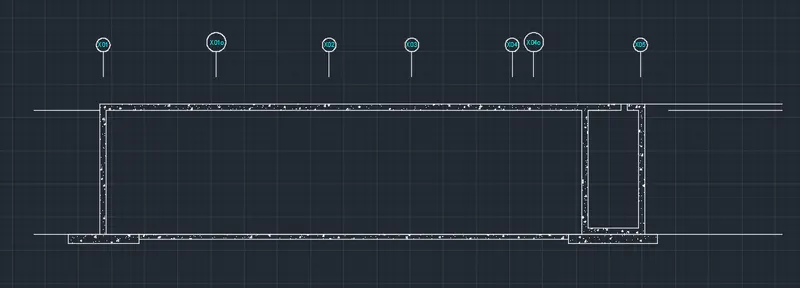
⦁ create the inside walls by using the line command.
⦁ use the command multitext to create the text.
⦁ use the command dimsty to set the dimensions value.
⦁ use the dimlin and dimcon command to measure and show the dimensions.
⦁ use the trim command and provide the manhole for the dimension of 750x750mm.
⦁ use the mtext command and name the level surface.
RESULT:
⦁ The section view of an industrial building is drawn by using the autocad.