Project 1 _Creating an Architectural plan for the provided plot size and develop relevant basic structural drawings
AIM :
To design and draft the layout of a residential building of plot size 60'x20' (18.3mx6m) facing east. Develop architectural drawings such as floor plan, elevations, sections and develop structural drawings such as column, beam, footing.
INTRODUCTION :
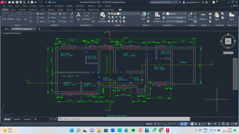
A Residential building of G+1 is sketched in the given plot size 18.3mx6m(18300mmx6000mm) East facing. The ground floor consists of patio, foyer, court, living room, 2 bedrooms, kitchen, dining and parking. The first floor consists of family room, 2 bedrooms, store room, hallway and balcony. Terrace floor consists of servent room and head room. All dimensions are in mm in this project.
- The objective of this project is to sketch the floor plans such as ground floor, first floor and terrace floor.
- To sketch the structural drawing such as column layout, footing layout and beam layout.
Ground floor plan details
- Patio - 1829x1524
- Foyer - 1905x1524
- Court - 1829x1638
- Living - 3964x3048
- Bedroom - 3658x3048
- Toilet #1 - 1524x1629
- Guest bedroom - 3048x3048
- Toilet #2 -1829x1219
- Kitchen -3048x2477
- Dining -2134x2477
- parking - 2781x4312
First floor plan details
- Family room - 3048x4382
- Bedroom - 3658x3048
- Toilet #1 -1524x1829
- Kids bedroom - 2325x3048
- Toilet #2 - 1524x1829
- Store room - 3048x2477
- Balcony - 2134x2477
- Terrace - 2781x4362
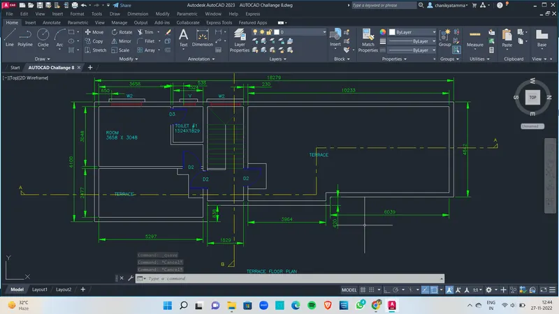
Terrace floor plan details
- Servent room - 3658x3048
- Toilet - 1524x1829
Wall details
- Exterior wall - 230
- Interior wall - 115
Doors and windows detail
- D1 - 1100x2100
- D2 - 900x2100
- D3 - 800x2100
- W1 - 2000x1600
- W2 - 1500x1600
- V - 600x600
Staircase details
- Raise - 152.4
- Thread - 250
Structural elements details
- Footing - 1200x1200
- Column - 230x300 and 300x230
- Plinth beam - 230x300
- Floor beam - 230x300
- Slab - 115
PROCEDURE :
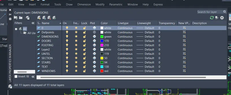
- Create the new layers that is used in this project. By typing 'LA' command and create new layers.
Architectural drawings
1. Ground floor plan
- Set the view cube as east facing by clicking the arrow behind the view cube.
- Change the UCS as x-axis facing in north and y-axis facing in west.
- Create construction line in the horizontal and vertical direction.
- Offset the lines at a distance of 230mm
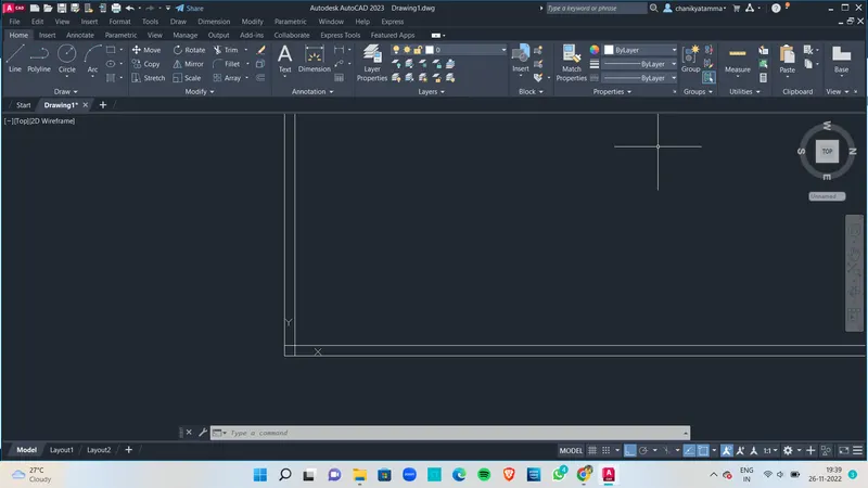
- Offset the vertical construction line next by next to the following distances 3048, 115, 2134, 230, 1829, 230, 1905, 230, 1829, 230, 3048, 2781 and 230.
- Offset the horizontal construction line next by next to the following distances 2477, 115, 3048 and 230.
- Again Offset the horizontal construction line next by next to the following distances 838, 230, 1524, 230, 3048 and 230.
- Again Offset the horizontal construction line next by next to the following distances 420, 230, 4612 and 230.
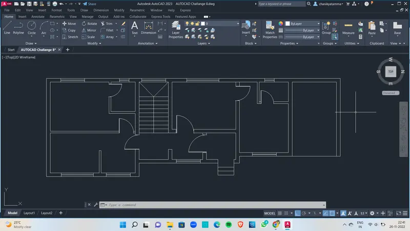
- Using trim command to trim the unwanted lines to create the floor plan layout.
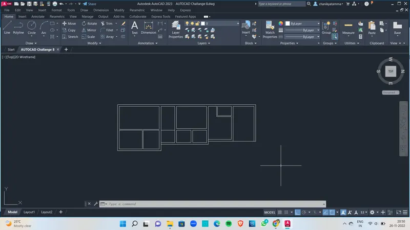
- Using Offset and trim command create the toilets in the bedroom.
- Create the stair unit landing as 914mm and thread as 250mm.
- Create the outer steps of thread 250mm.
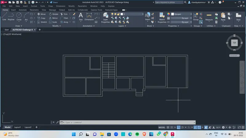
- Place the doors and windows in the required places.
- Make cutout in the kitchen and in the foyer area walls.
- Set the text style as roman.shx by using 'st' text style in the command line.
- Create a new dimension style by opening dimension style manager.
- Set the arrowhead as 'obilique'
- Set the primary unit as 'decimal' and precision as 0.
- Create text by typing 'MT' command in the command line.
- Specify the room name and sizes.
- Create a dimension line by usig 'Dimlin' command.
- Dimension the ground floor plan.
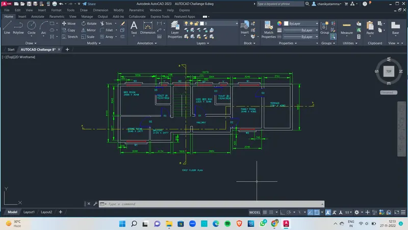
2. First floor plan
- Turn off the dimension layer and text layer by open the layer properties manager.
- Copy the ground floor plan and place it to the another place.
- Remove the walls in the patio and court area.
- Patio and court area combined to form the hallway in first floor.
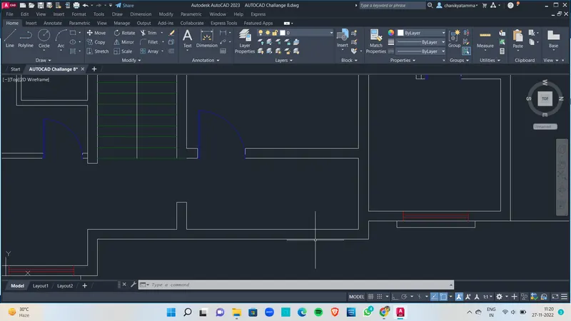
- Court and dining area combined to form the balcony in first floor.
- Then living room in the first floor changed to kids bedroom in first floor.
- Create a toilet in the kids bedroom by offset the right side wall and the top wall at a distance of 1524 and 1829 respectively.
- Offset the offseted line at a distance of 115mm in outer side to make a 115mm thick wall'
- Create a parapet wall in the parking area it will become terrace in the first floor.
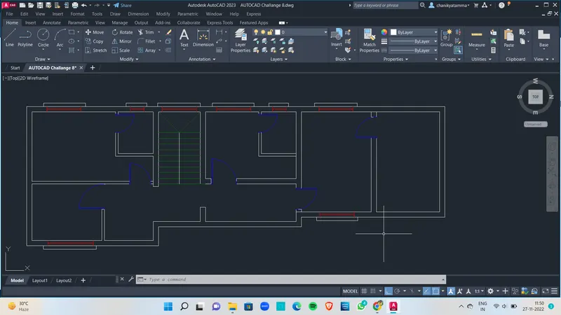
- Create a text to specify the room names and sizes by using 'MT' multiline text command.
- Dimension the first floor plan by using 'dimlin' command.
3. Terrace floor plan
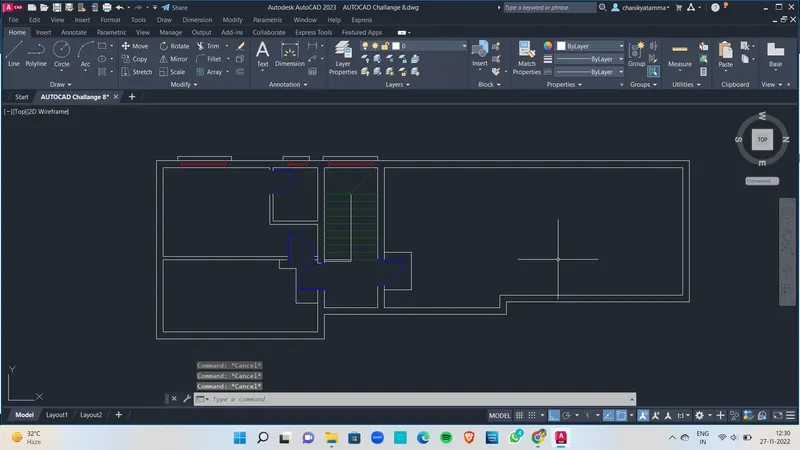
- Turn off the dimension layer and text layer by open the layer properties manager.
- Copy the ground floor plan and place it to the another place.
- Using errase command by typing 'E' in the command line.
- Remove the walls that are in the right side of the stair area.
- Remove wall in between the balcony and store room.
- Remove the terrace area in the first floor.
- Extend the walls in stair right and left to join the outer wall.
- Place doors and windows in the required places.
- Create a text to specify the room names and sizes by using 'MT' multiline text command.
- Dimension the first floor plan by using 'dimlin' command.
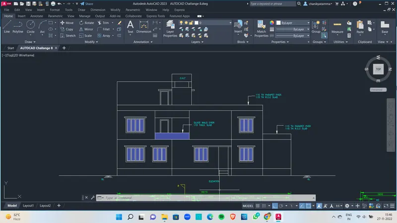
4. Elevation
- Turn off the dimension and text layers by opening the layer properties manager.
- Copy the ground floor plan and place it someware in the drawing.
- Cereate vertical construction lines in the edges of the ground floor plan.
- Create horizontal construction line this is the ground level of the elevation.
- Offset form the ground level to make the elevation.
- Offset at a distance of 300mm, 3048mm, 3048mm, 3048mm.
- Offset the last offseted line at a distance of 1521mm and 600mm and 1200mm.
- Trim the unwanted lines in the construction line.
- Make a windows and doors reference line by using construction line.
- Create a doors and windows in the required position.
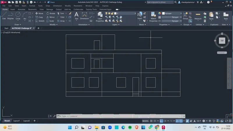
- Create a lintel and sunshade in the places of doors and windows.
- Using multiline text by typing 'MT' in the command promt.
- Create texts when the needed places in the elevation drawing.
- Place the doors, windows, sunshade and walls in its layer.
5. Section A-A
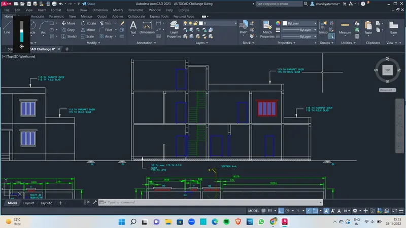
- Create construction lines in the section of the ground floor plan.
- Create a horizontal construction line in the created construction lines.
- Offset the horizontal construction line at a distance of 300mm.
- Offset the ground level at a distance of 25mm in the negative y-axis and 75mm in the positive y-axis. This is the I.P.S below thw P.C.C.
- Offset the I.P.S line at a distance of 175mm. This is the floor finishing.
- Remove the unwanted construction lines.
- Create a reference line in the places of doors and windows in the ground floor and make doors and windows in the section drawing.
- Copy the elevetion and place it above the first floor plan.
- Make a reference line in the places of doors and windows in the first floor plan.
- Create a doors and windows in the elevation drawing.
- Copy the elevation drawing in and place it above the terrace floor drawing.
- Create a reference lines in the place of doors and windows and create doors and windows.
- Create text by typing 'MT' in the command prompt.
- Make text in the needed places.
- Dimensioning the elevation drawing by using linear dimension.
6. Section B-B
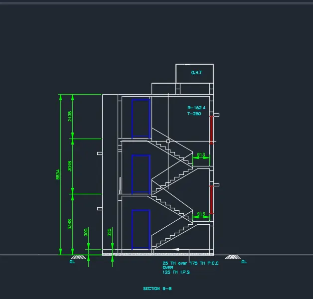
- Copy the ground floor plan and rotate it 90 deg.
- Make the referece line in the section B-B by using construction line.
- Create a horizontal construction line. This is the ground level of the building.
- Offset the horizontal construction line at a distance of 300mm.
- Offset the ground level at a distance of 25mm in the negative y-axis and 75mm in the positive y-axis. This is the I.P.S below thw P.C.C.
- Offset the I.P.S line at a distance of 175mm. This is the floor finishing.
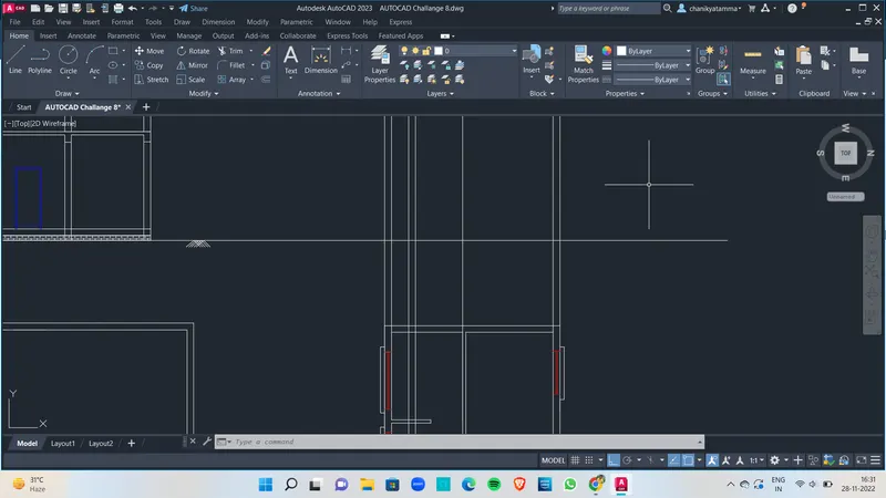
- Make a reference line in the staircase by using construction line.
- Create a staircase of rise 152.4mm and thread 250mm.
- Create doors and windows in the elevation drawing by using reference line.
- Create a sunshade and lintel beams and beams in the section drawing.
- Create text by typing 'MT' in the command prompt.
- Make text in the needed places.
- Dimensioning the elevation drawing by using linear dimension.
Structural drawings
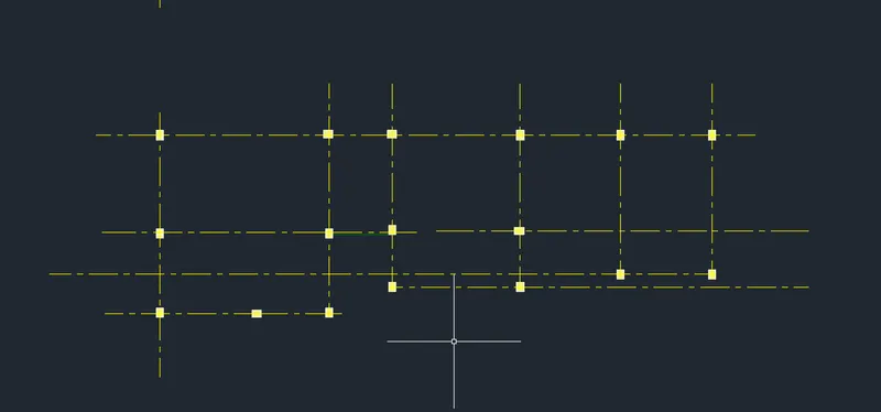
1. Column layout
- Using rectangle tool, create a rectangle of size 230x300 and 300x230.
- Turn off the dimension layer and text layer by using the layer properties manager.
- Copy the ground floor plan and place it to the another place.
- Place the column of size 230x300 and 300x230 in the ground floor plan.
- Offset the walls lines 1/2 of the thick of walls. This is the grid line of the column layout.
- Using layer iso by typing 'Layiso' in the command prompt.
- Isolate the column and grid layers.
- Copy the isolated layers and place it to the another place.
- Create the grid names by using 'MT' command and create a circle around the text.
- Using dimension linear command.
- Dimension the columns from the grid line arround the columns.
- Dimension the grid to grid spacing.
- Repeat the same procedure to create the first floor and terrace floor column layouts.
2. Footing layouyt
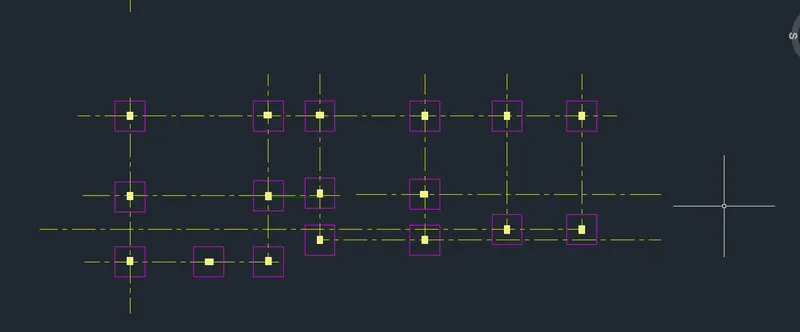
- Turn off the dimension layer and copy the ground floor column layout.
- create rectangle of size 1200x1200mm using rectangle tool.
- Place the footing in the column layout with reference to the grid lines.
- Using dimension linear command, dimension the footing arround with the reference of the grid lines.
- Mention the names of the footing with the reference of the dimension of the footing with reference to the grid lines.
- Using the layer isolate command, isolate the column and footing layer.
- Copy the F4 footing and place it to the another place.
- Dimension the footing and create a section line.
3. Beam layout
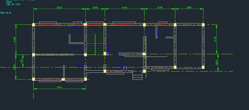
Ground floor beam layout
- Repeat the same procedure of the plint beam layout.
Result :
The layout of residential building of plot side 18.3mx6m is created. The architectural drawings like floor plans, elevation, sections and the structural drawings like column, footing and beam layout are developed. The results are shown below.
Architectural drawings
1. Ground floor plan
2. First floor plan
3. Terrace floor plan
4. Elevation
5. Section A-A
6. Section B-B
Structural drawings
1. Column layout
2. Footing layout
3. Beam layout