Project 1 _Creating an Architectural plan for the provided plot size and develop relevant basic structural drawings
Aim: To draft the floor plan of the house in a 60’x20’ East facing and draft its Elevation, Section and layout of Column , Beam and Footing using AutoCAD
Commands Used:
- LINE: Draw lines in AUTO CAD
- POLYCON: Draw polycons with three or more sides
- RECTANGLE: Used to draw rectangles.
- CIRCLE: Command used to draw circles
- ELLIPSE: Used to draw ellipse
- ERASE: Erase object in the drawing area.
- COPY: Used to copy one or more objects
- MIRROR: Command used to mirror an exact duplicate of an object.
- OFFSET: Used to offset one object from another a distance you specify
- EXTEND – Used to extend one line to another.
- ARRAY – Use to make a rectangular or polar array of an object.
- MOVE - Used to move objects around in the drawing area
- Rotate- Used to rotate an object around a base point.
- SCALE- Command used to make an object larger or smaller.
- TRIM: Command used to trim an object from another object.
- CHAMFER- Used to put a chamfer between two lines.
- FILLET – Used to put a fillet between two lines of a radius you specify.
- DIMSTYLE- Used to modify the dimensions.
- HATCH – for hatching the objects.
- STRETCH – Used to stretch the one point of object
- SCALE – Used to resize the model/drawing itself.
Procedure:
- Open AutoCad
- Selecting Imperial system
- Command UN(units) and selecting Engineering with precision of 0’-0.0”
- Command LIMITS and having limit of (0’,0’) in lower left corner and (10000’,10000’) in upper right corner
- Command ZOOM and selecting All
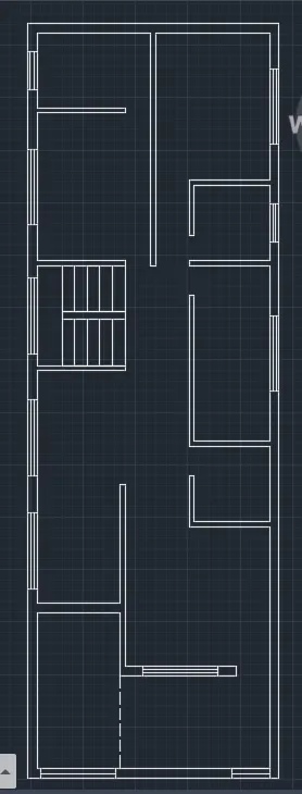
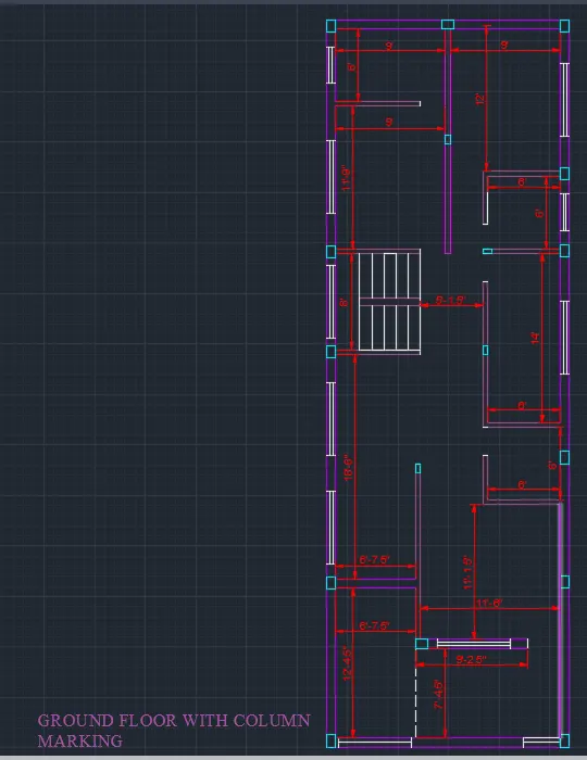
1. Ground Floor Plan
- Open auto cad and enter UN(units command) in the command box and select type as engineering and set precision of decimal as 0'0".
- Select X line command and draw horizontal line and vertical line.
- Trim the unwanted lines.
- Now select offset command and give an offset of 9" to both horizontal and vertical line drawn by X line.
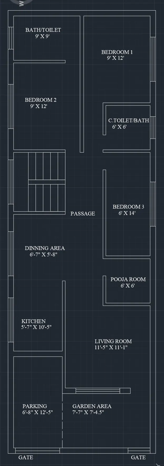
- Give the offsets as follows in the X direction.
- Offset 9' X 12' for bedroom1.
- Offset 4.5" for internal wall.
- Offset 9' X 9' for attached bath/ toilet.
- Offset 6" for partition wall.
- Offset 9' X 12' for bedroom2.
- Offset 6' X 6' for comman toilet.
- Give the offsets 7' X 8' for staircase.
- Offset 6' X 14' for bedroom3.
- Offset 6'-7" X 5'-8" for dinning area.
- Offset 5'-7" X 10'-5" for kitchen.
- Offset 6' X 6' for pooja room.
- Offset 11'-5" X 11'-1" for living room.
- Offset 6'-8" X 12'-5" for parking area.
- Offset 7'-7" X 7'-4.5" for Garden area.
Result:
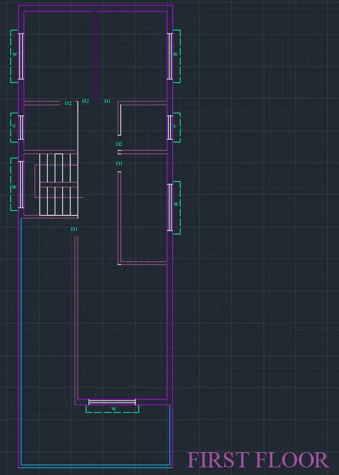
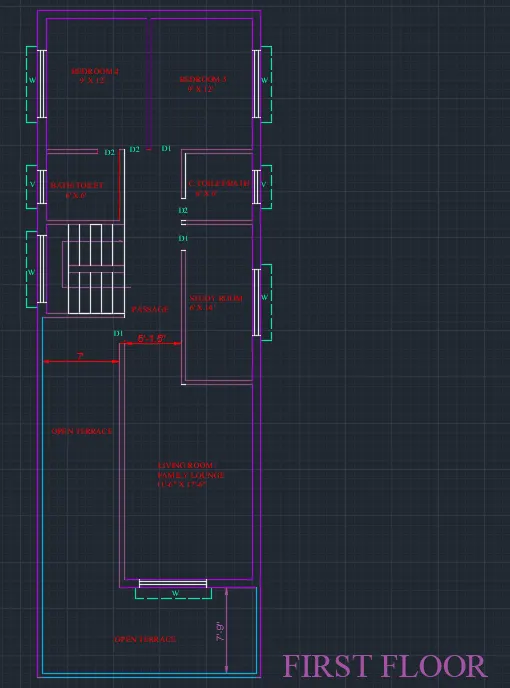
2. First Floor Plan
- Open auto cad and enter UN(units command) in the command box and select type as engineering and set precision of decimal as 0'0".
- Select X line command and draw horizontal line and vertical line.
- Trim the unwanted lines.
- Now select offset command and give an offset of 9" to both horizontal and vertical line drawn by X line.
- Give the offsets as follows in the X direction.
- Offset 9' X 12' for bedroom 4 and 5.
- Offset 4.5" for internal wall.
- Offset 6' X 6' for attached bath/ toilet.
- Offset 6" for partition wall.
- Offset 6' X 6' for comman toilet.
- Give the offsets 7' X 8' for staircase.
- Offset 6' X 14' for Study room.
- Offset 11'-6" X 17'-6" for living room.
- Offset 6'-8" X 12'-5" for parking area. / Family lounge area.
- Offset for Open terrace.
Result:
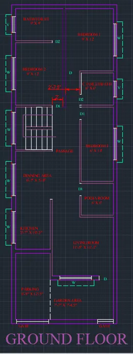
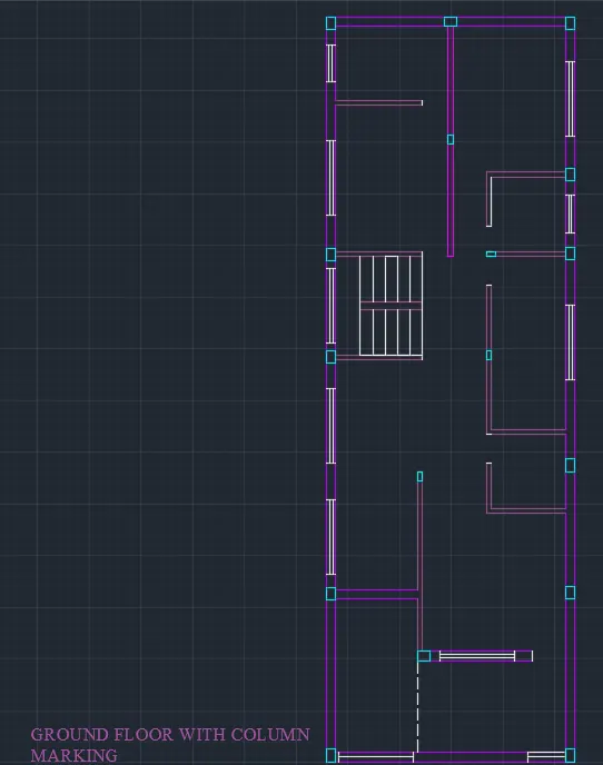
Ground floor drawing with column marking:
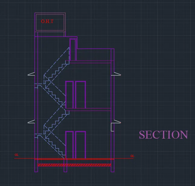
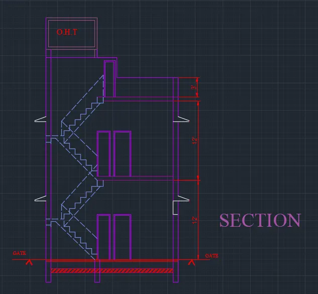
3. Section A-A
Commands used:
Xline
- Xline horizontal and vertical is used to start the drawing initially
Line
- Line is used to draw the line in the Window, Doors, Ventilators, Staircase and lines at required spaces
Offset
- Offset is used to offset the Floor height to 12’
- Offset is used to offset the Parapet Wall to 3’
- Offset is used to offset the GL line to 2’
Pline
- Pline is used to draw the Chejjas above the windows and ventilators
- Pline is used to draw the staircase of the building
- Pline is used to draw the Over Head Tank
Trim
- Trim is used to trim the unwanted lines
Result:
4. Front Elevation
Commands used:
Xline
- Xline horizontal and vertical is used to start the drawing initially
Line
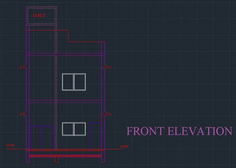
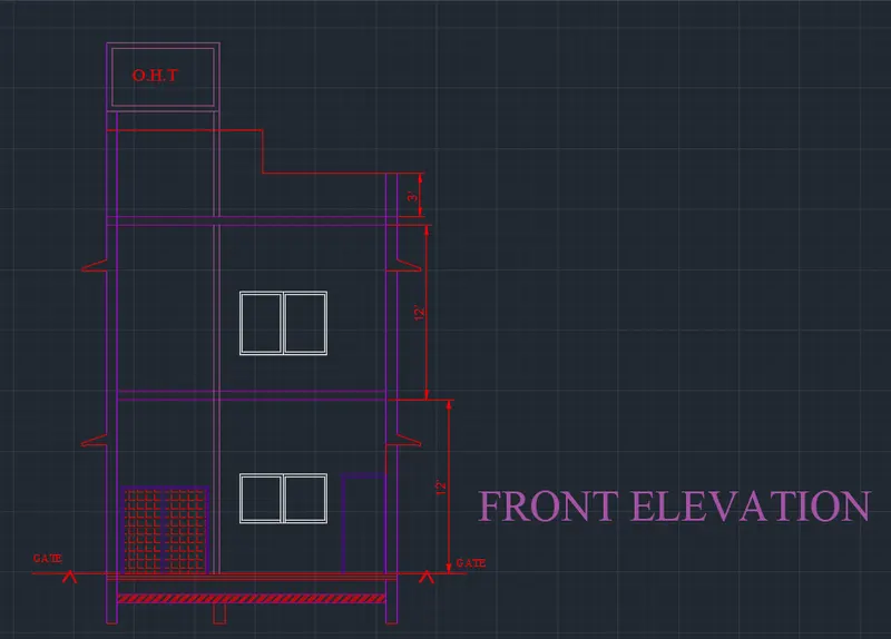
- Lineis used to draw the line in the Window, Doors, Ventilators and lines at required spaces
Offset
- Offset is used to offset the Floor height to 12’
- Offset is used to offset the Parapet Wall to 3’
- Offset is used to offset the GL line to 2’
Pline
- Pline is used to draw the Chejjas above the windows and ventilators
Trim
- Trim is used to trim the unwanted lines
Result:
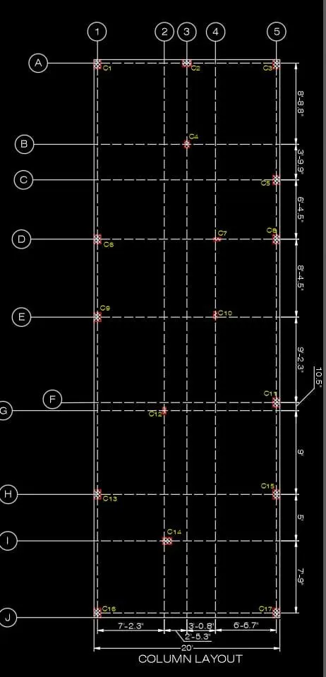
5. Layout of Column
PLINE
- PLINE is used to draw the Column of size 9"x12" and 9"x9" with appropriate orientation
LINE
- LINE is used to draw the Horizantal and Vertical line to the center of the Column .
LINETYPE
- LINETYPE is to change the Continuous line to Dash line and changing the scale to 10
TRIM
- TRIM is used to trim the unwanted lines
Annotate Tab
- In Annotate Tab>Modify dimension style>Text and Style
- Changing the style from ISO25 to Swis 721> Set current>Apply
TEXT
- TEXT is used to write the number of Column
DIMLINEAR
- DIMLINEAR is used to dimension center to center distance of the Column
MLEADERSTYLE
- MLEADERSTYLE> content> mleader type> Block> source block>circle
MLEADER
- MLEADER is used to leader the horizontal lines as 1 to 5
- MLEADER is used to leader the vertical lines as A,B,C,D,E,F,G,H,I and J
HATCH
- HATCH is used to hatch the foundation to ANS137 for 9"x12" and 9"x9"
ERASE
- ERASE is used to erase the unwanted lines which cannot be trimmed using Trim Command
Result:
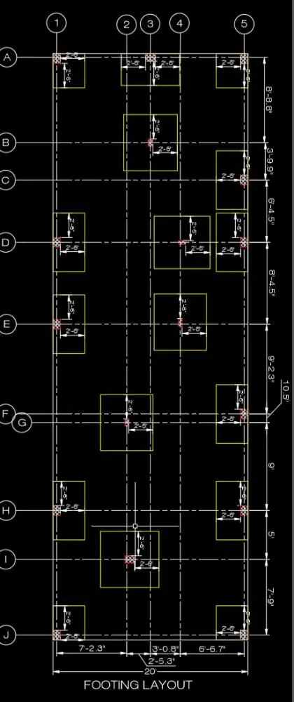
6. Layout of footing
PLINE
- PLINE is used to draw the Column of size 9"x12" and 9"x9" with appropriate orientation
LINE
- LINE is used to draw the Horizantal and Vertical line to the center of the Column .
OFFSET
- OFFSET is used to offset the footing dimension to 2’-6”
LINETYPE
- LINETYPE is to change the Continuous line to Long dash - Short dash line and changing the scale to 10
TRIM
- TRIM is used to trim the unwanted lines
Annotate Tab
- In Annotate Tab>Modify dimension style>Text and Style
- Changing the style from ISO25 to Swis 721> Set current->Apply
DIMLINEAR
- DIMLINEAR is used to dimension center to center distance of the Column
MLEADERSTYLE
- MLEADERSTYLE> content> mleader type> Block> source block>circle
MLEADER
- MLEADER is used to leader the horizontal lines as 1 to 5
- MLEADER is used to leader the vertical lines as A,B,C,D,E,F,G,H,I and J
HATCH
- HATCH is used to hatch the foundation to ANS137 for 9"x12" and 9"x9"
ERASE
- ERASE is used to erase the unwanted lines which cannot be trimmed using Trim Command
Result:
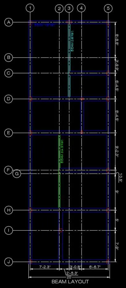
7. Layout of Beam
PLINE
- PLINE is used to draw the Column of size 9"x12", 4.5"x9" and 9"x9" with appropriate orientation
LINE
- LINE is used to draw the Horizantal and Vertical line to the center of the Column .
- LINE is used to draw the Lines of beam of size 9’x9’
LINETYPE
- LINETYPE is to change the Continuous line to Long dash - Short dash line and changing the scale to 10
TRIM
- TRIM is used to trim the unwanted lines
Annotate Tab
- In Annotate Tab >Modify dimension style>Text and Style
- Changing the style from ISO25 to Swis 721> Set current>Apply
DIMLINEAR
- DIMLINEAR is used to dimension center to center distance of the Column
MLEADERSTYLE
- MLEADERSTYLE> content> mleader type> Block> source block>circle
MLEADER
- MLEADER is used to leader the horizontal lines as 1 to 5
- MLEADER is used to leader the vertical lines as A,B,C,D,E,F,G,H,I and J
ERASE
- ERASE is used to erase the unwanted lines which cannot be trimmed using Trim Command
Result: