Project 1 _Creating an Architectural plan for the provided plot size and develop relevant basic structural drawings
1.AIM
To draw the Floor Plan, Elevation and section of Residential Buildings using the various commands in Auto CAD.
PROCEDURE
- To create a new drawing sheet .
- Type ,,UN’ to set the units of current format of measure.( FEET and INCHES)
- Type ,,LIMITS’ to set the maximum dimension limits on the particular page.
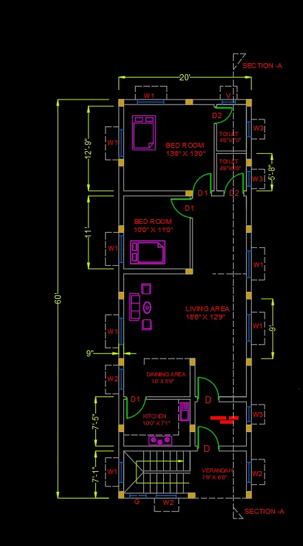
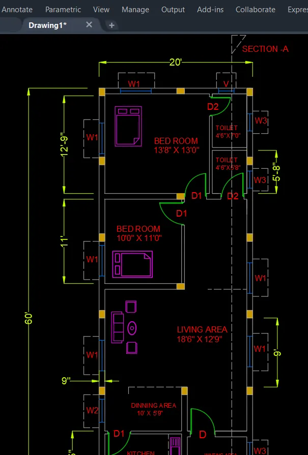
- To draw the layout of residential building of the given criteria for a plot size is 60’ x 20’(18.3m x 6m).
- The site facing orientation is EAST.
- First to study the facing direction of VAASTU SHASTRA like the direction of North-East, North-West, South-East and South-West.
- Type ,,L’ - Line commands allows to creating a line where the end points allows creating a line where the end points are dimensional co-ordinates.
- TYPE ,, XLINE’ to draw the infinity length of line, can be draw it free or set it to be Horizontal or Vertical, follow a certain angle.
- The direction of plot at X in 20’ and Y in 60’.
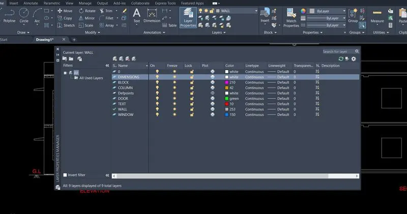
- Then to select the different layer properties of various objects to better understanding of drawing, like Wall, Door, Window, Blocks, text, etc..,
- Type ,, OFF’ – offset command to create a new object that specified distance from an existing objects or through a specified points.
- Here , we take the offset Thickness of Exterior wall is 9”(230mm) and Interior wall is 4.5”(120mm).
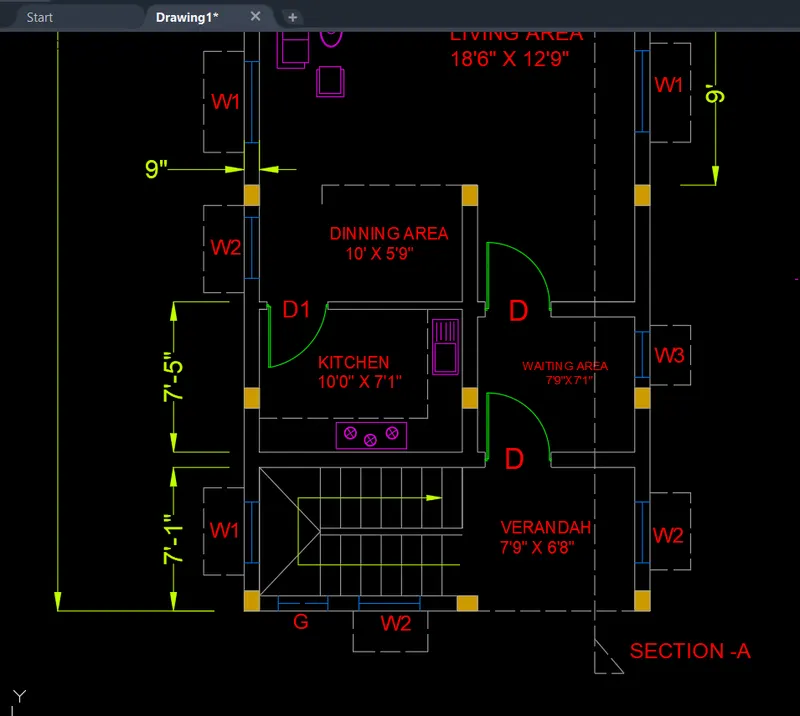
- Then to split the various areas of our requirement like Bedrooms, Hall, Kitchen, Dinning hall, Verandah, Waiting hall, Toilets,etc..,
- Analyze the direction of wind forces and to fix the Windows to better Air circulation in the building.
- This comes after to fix the Door at any corner end of the room for without disturbing.
- Main door is fixed at center of the area from north side.
- Fix the columns after judging the loading properties.
- Type ,, Tr’ – Trim command is used to trims off an objects cutting the extra edges on objects.
- Type ,, Text’ to create the text ( SINGLE or MULTI ), select and change the properties of standard size.
- The text size is 9”(230mm)
- The text color is selected the layer properties of RED.
- COPY – this commands is used to selected objects from a given square to destination, learning a copy at the originally selected location.
- ROTATE – rotate the objects around a specified point.
- MOVE – moves the objects to the destination place from the source place.
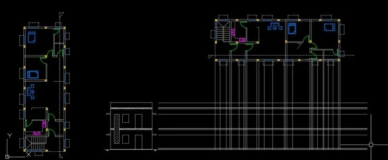
- After drawn the plan, to take the section of AA.
- TYPE ,,DLI’ in command bar to give the dimension of the plan.
- TYPE ,,D’ in command bar to give the size of the dimension and size of the arrows, changing tool command is DDIM.
- The dimension Color of the layer properties of Green.
- After, finishing the floor plan, then to draw the elevation and cross section of the plan.
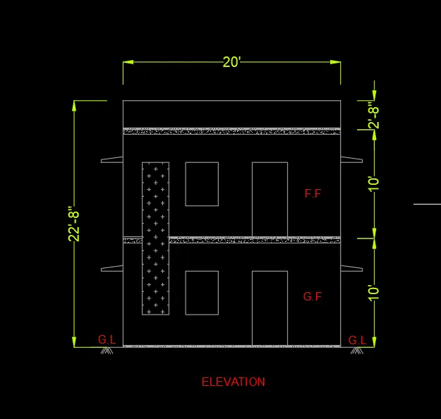
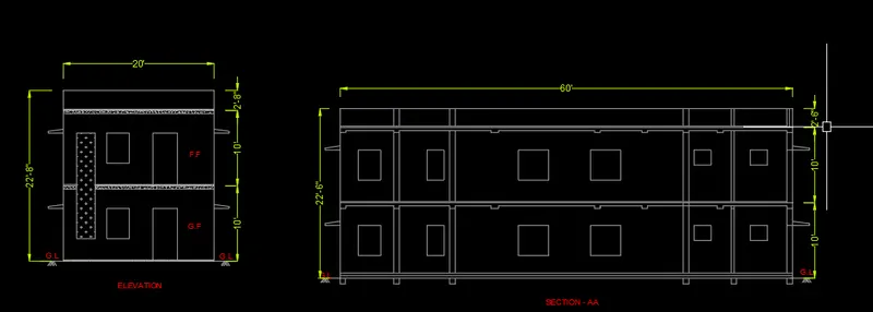
- The elevation is designed of G+1 of residential building.
- The floor height is 10 feet at each from Ground level.
- The reference baseline of the elevation is facing side of the plan.
- After to project the fixed properties of Door, windows, slab at elevation site.
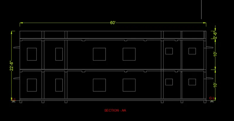
- To draw the cross sectional plan at the section-AA .
- The same procedure of the elevation step by step process.
- Finally, to save the diagram .
RESULTS
The diagram of the Floor Plan, Elevation and section-AA is drawn as per dimensions using the software of Auto.
DIAGRAM
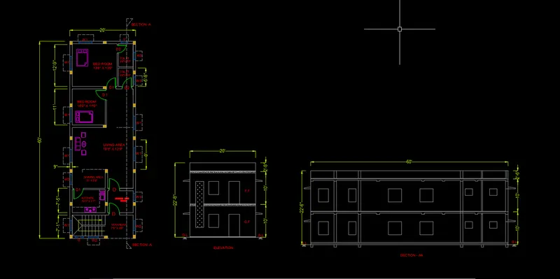
2.AIM
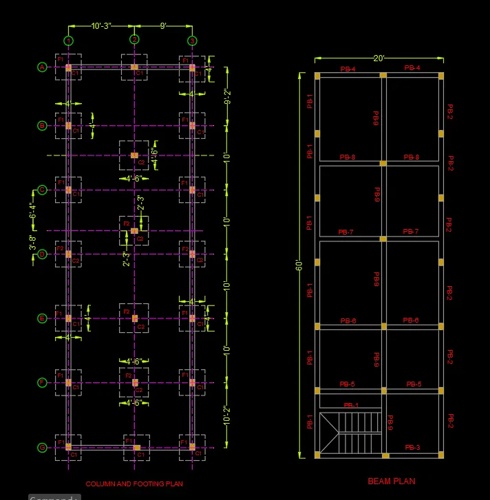
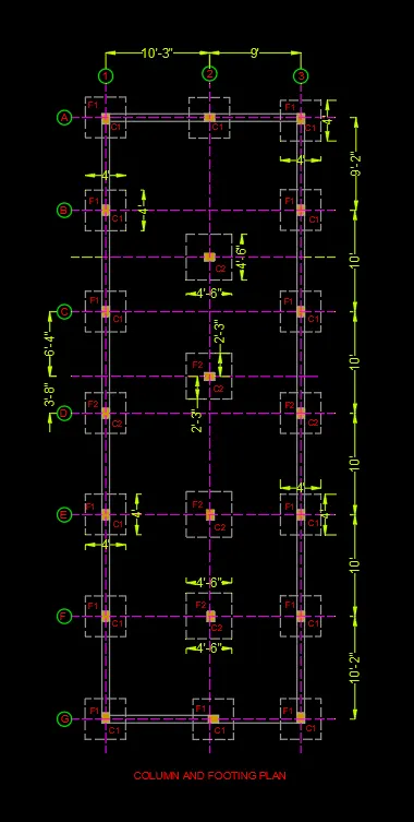
To draw the Column, Beam and Footing plan of Residential Buildings using the various commands in Auto CAD.
PROCEDURE
- Type ,,UN’ to set the units of current format of measure.( FEET and INCHES)
- Type ,,LIMITS’ to set the maximum dimension limits on the particular page.
- To take the Column place from the reference of Floor plan.
- Then, to analyze the loading calculation of the entire building for provide the footing designs.
- The projection line is drawn from floor plan required Size.
- Here , we select the column size is 1’ x 9” and 9” x 9”
- The footing size is 4’ x 4’ and 4’6” x 4’6”.
- The Grid lines is drawn to centroidal axis of the column marking to fix the column .
- To give the name of each and every grid lines for better understading.
- Type ,, Tr’ – Trim command is used to trims off an objects cutting the extra edges on objects.
- Type ,, Text’ to create the text ( SINGLE or MULTI ), select and change the properties of standard size.
- COPY – this commands is used to selected objects from a given square to destination, learning a copy at the originally selected location.
- ROTATE – rotate the objects around a specified point.
- MOVE – moves the objects to the destination place from the source place.
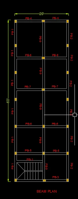
- The same procedure to follow the beam layout.
- Before to check the load acting on the beam, then to design the beam size.
- TYPE ,,D’ in command bar to give the size of the dimension and size of the arrows, changing tool command is DDIM.
- The dimension Color of the layer properties of Green.
- Finally, to save the diagram .
RESULTS
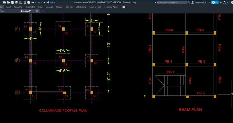
The diagram of the Column, Beam and footing plan is drawn as per dimensions using the software of Auto.
DIAGRAM